


USER MANUAL
P INTSPY INTPSPY
SURVEILLANCE CAMERA | TINY SERIES
TINY-W
3
TINY
4G
TINY-W
BF
TINY-7
TINY-PLUS
v1.6

P INTSPY INTPSPY
THANK YOU FOR CHOOSING A SPYPOINT PRODUCT.
This manual will guide you through all the features of your device
so that you will get optimal use out of your SPYPOINT product.
Our priority is to provide outstanding customer service. If you need
support for your product, please contact the SPYPOINT technical
service or visit our website.
CONTACT
1-888-779-7646
tech@spypoint.com
www.spypoint.com
ABOUT US
GG Telecom’s mission is to offer products that are easy
to use, innovative, affordable and of exceptional quality.
Our SPYPOINT products are mainly used for hunting and
residential/commercial surveillance. They are distributed and
shipped all over the world and the market never stops growing.
Prosperous and respected, GG Telecom is a company that constantly
keeps abreast of new technologies and listens to its customers to
deliver cutting-edge products with practical solutions that improve
hunting and outdoor activities.
JOIN THE SPYPOINT COMMUNITY
facebook.com/spypoint
youtube.com/spypointtrailcam
twitter.com/SpypointCamera
vimeo.com/spypointxcelcam
twitter.com/SpypointCamera
vimeo.com/spypointxcelcam
youtube.com/spypointtrailcam
twitter.com/SpypointCamera
vimeo.com/spypointxcelcam
CAMERAS WITH CELLULAR TRANSMISSION
• If you need information or would like to subscribe to mySPYPOINT service, go to www.myspypoint.com.
• For the latest version of the activation procedure, go to support.spypoint.com/activation.

3
Package contents ....................................................................... 4
Components
Camera ........................................................................................ 5
Receiver
(BLACKBOX) ...................................................................... 7
Controller
(BLACKBOX-D).................................................................. 8
Controller (BLACKBOX-4G) ................................................................ 9
Power
Camera ...................................................................................... 10
Receiver
(BLACKBOX) .................................................................... 11
Controller
(BLACKBOX-D/BLACKBOX-4G) ............................................. 12
Memory card
Camera ...................................................................................... 14
Receiver
(BLACKBOX) .................................................................... 15
Controller
(BLACKBOX-D/BLACKBOX-4G) ............................................. 16
SIM card
Controller
(BLACKBOX-4G) .............................................................. 16
BUSY LED
Camera ...................................................................................... 14
Controller
(BLACKBOX-D/BLACKBOX-4G) ............................................. 16
Antenna installation (TINY-PLUS) ................................................. 14
Settings (camera) ........................................................................ 17
Setup
Receiver
(BLACKBOX) .................................................................... 23
Controller
(BLACKBOX-D)................................................................ 25
Controller
(BLACKBOX-4G) .............................................................. 28
REMOS Technology
(TINY4G) ........................................................ 22
Sound recording (camera) ........................................................... 33
External triggering (camera) ....................................................... 33
Table of contents
File transfer to a computer
Camera ...................................................................................... 34
Receiver
(BLACKBOX) .................................................................... 35
Controller
(BLACKBOX-D/BLACKBOX-4G) ............................................. 35
Troubleshooting
Camera ...................................................................................... 36
Receiver
(BLACKBOX) .................................................................... 38
Controller
(BLACKBOX-D)................................................................ 39
Controller
(BLACKBOX-4G) .............................................................. 40
Error messages
Camera ...................................................................................... 37
Controller
(BLACKBOX-D)................................................................ 39
Controller
(BLACKBOX-4G) .............................................................. 40
Available accessories
Camera ...................................................................................... 41
Receiver
(BLACKBOX) .................................................................... 43
Controller
(BLACKBOX-D/BLACKBOX-4G) ............................................. 44
Specications
TINY-7 ....................................................................................... 45
TINY-PLUS .................................................................................. 46
TINY-W
BF
.................................................................................... 47
TINY-W
3
..................................................................................... 49
TINY4G ........................................................................................ 51
Regulation ................................................................................ 53
Limited warranty ...................................................................... 22
Repair service ........................................................................... 22

4
Package contents
USB
cable
Audio-video
cable
Installation strap
(TINY-7, TINY-PLUS)
Camera
(TINY-7)
Camera (TINY-PLUS,
TINY-WBF, TINY-W3, TINY4G)
BLACKBOX receiver
(TINY-WBF)
BLACKBOX-D controller
(TINY-W3)
Installation straps
(TINY-WBF, TINY-W3, TINY4G)
Quick start guide
(camera)
Quick start guide
(TINY-W
BF
receiver,
TINY-W3 controller)
Quick start guide
Wireless backup system
v1.4
P INTSPY INTPSPY
Models:
BLACKBOX
TM
(receiver included with TINY-WBF)
BLACKBOXTM-D
(controller included with TINY-W3)
Getting started
Setup of the
BLACKBOX
receiver
Complete instructions
www.spypoint.com
Setup of the BLACKBOX-D
controller
Error messages
1
2
3
4
5
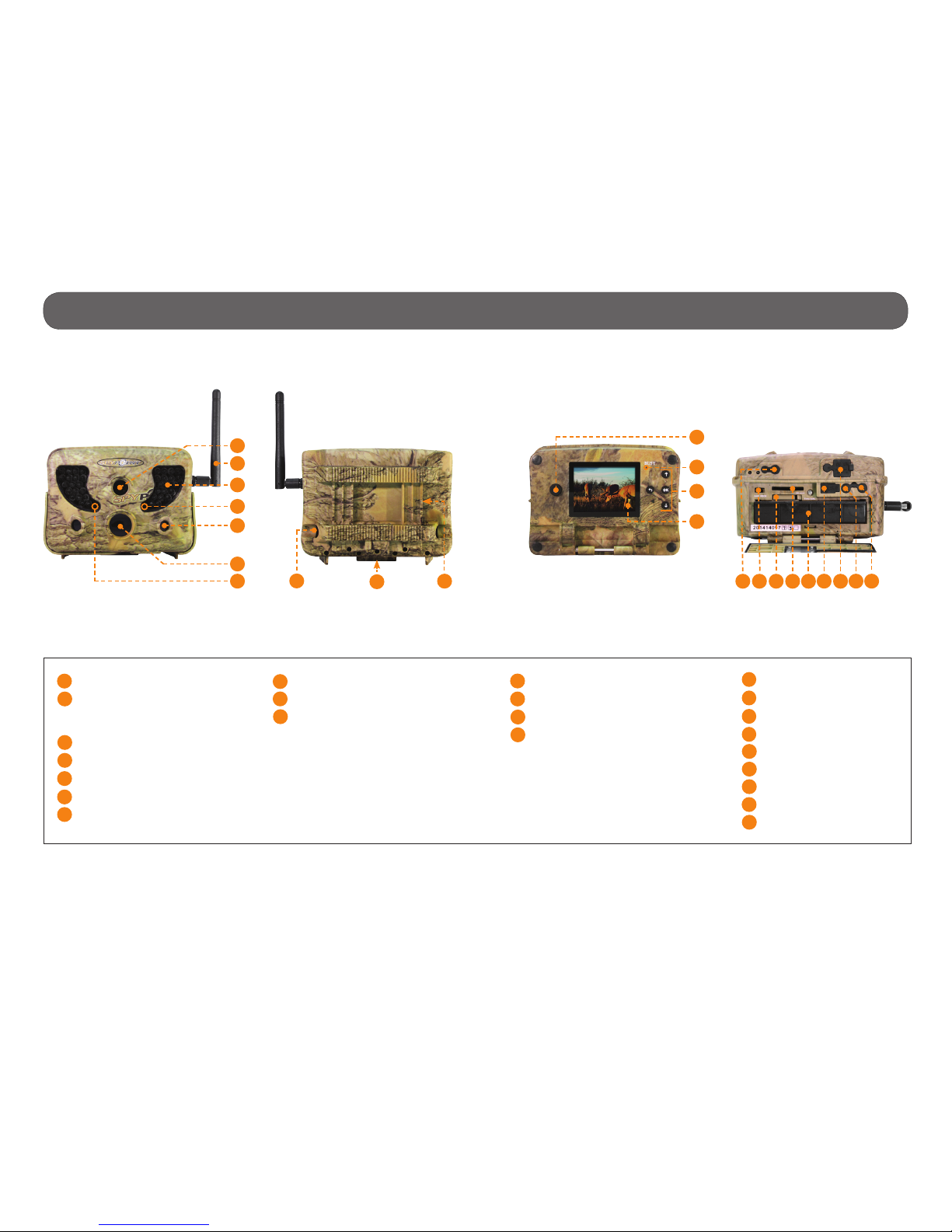
COMPONENTS
BLACKBOX
Receiver
BLACKBOX-D
Controller
3
1
2
4
5
6
7
Getting started
1
2
4
3
11
12
10
5
1
7
8
9
1 Antenna Allows wireless communication between the
BLACKBOX and the camera.
2
1)
12V power
jack
2)
Solar panel
jack
(BLACK-
BOX-D only)
1) The devices can be powered from an ex-
ternal 12-volt DC input such as a 12V battery
or a 12V adapter, sold separately.
2) Allows the user to connect a solar panel
(SP-12V) to maintain the charge of the lithi-
um battery pack (LIT-09/LIT-C-8), sold sepa-
rately.
3 Slot for instal-
lation strap
Allows the user to install the device using the
installation strap included.
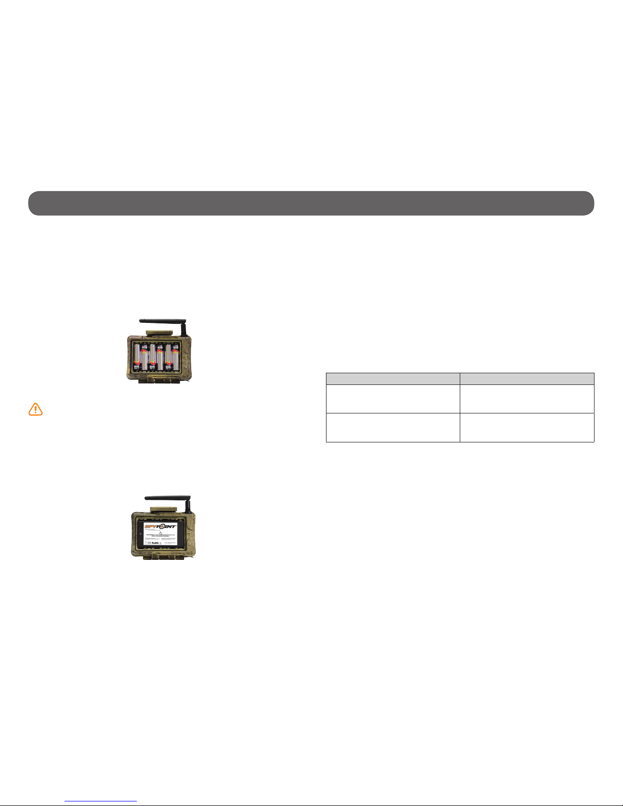
4 Battery case Insert 6 AA batteries (alkaline or lithium).
The BLACKBOX-D controller can also be pow-
ered by a rechargeable lithium battery pack
(LIT-09/LIT-C-8, sold separately).
5 SD card slot An SD card is required to record photos. The
devices accept SD/SDHC memory cards, up to
32 GB (not included).
6 Test light In the minute following turning on the receiver,
the rst 8 seconds allows the user to know the
battery status by the test light. Then, for the
rest of the time, the test light ashes rapidly to
indicates the synchronization period.
7 ON/OFF Allows the user to turn on/off the device.
8 BUSY LED Lights up when the controller is recording.
9 Viewing
screen
To access the main menu, see battery level
and view photos. Screen with zoom and pan
functions.
10 Navigation
buttons
Buttons to set the controller.
11 TV OUT
Allows the user to view or delete the recorded
photos on a television.
12 Battery switch Allows the user to select the power source
according to the type of batteries used.
BATTERY INSTALLATION
We recommend the use of new batteries to ensure a maximum
performance of the device. Rechargeable AA batteries are not
recommended.
Battery switch position (depending on the power source)
BLACKBOX-D controller only
Power source Battery switch position
• 6 AA
• 12V
• 12V + 6 AA
ALK
• LIT-09*
• 12V + LIT-09*
• Solar panel + LIT-09*
LIT-09
* Rechargeable lithium battery pack, sold separately (LIT-09) or with
a charger (LIT-C-8).
6 alkaline
AA batteries
BLACKBOX
6 alkaline
AA batteries
Lithium battery pack
LIT-09/LIT-C-8
BLACKBOX-D
INSERTING THE MEMORY CARD
Insert an SD/SDHC memory card in the card slot (up to 32 GB capacity).
The card is inserted correctly when a click is heard.
Before inserting or removing a memory card, always turn off the
device to prevent loss or damage of the photos already recorded.
BLACKBOX AND CAMERA INSTALLATION:
BLACKBOX BLACKBOX-D
TREE
SIGNAL STRENGHT
1
ORIENTATION
OF THE BLACKBOX
UNIT
SIGNAL
STRENGHT
2
HEIGHT
OF THE TWO
DEVICES
BLACKBOX-4G controller
(TINY4G)
Quick start guide
(TINY
4G
controller)
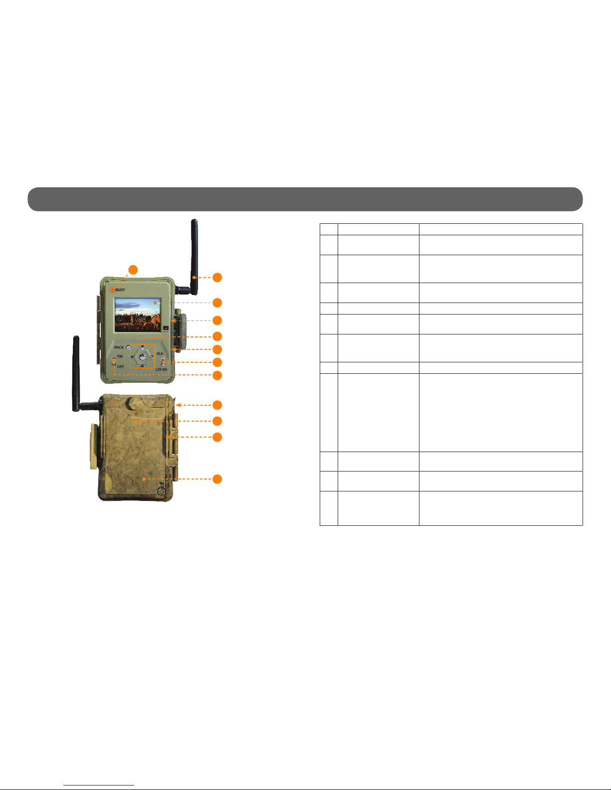
5
Microphone
Battery switch
Access to the time battery
SD card slot
Removable battery holder
USB port
12V/Solar panel jack
External trigger jack
TV out
Components • Camera
Power button
BUSY LED
Navigation buttons
Viewing screen
11
12
13
14
1
2
3
6
4
5
7
8
9
11
12
13
14
16 17 18 192021
22 23
Photos lens
Antenna
(TINY-PLUS, TINY-WBF, TINY-W3,
TINY4G)
Invisible LEDs
Test light
Side sensors (2)
Fresnel lens
Light sensor
1
2
3
4
5
6
7
10
Cable lock hole
Tripod mount
Slot for installation strap
8
9
10
15
22
21
15
16
17
18
20
19
23

6
Components • Camera
1 Photo lens Image sensor and infrared lter.
2 Antenna
(TINY-PLUS, TINY-WBF,
TINY-W
3
, TINY
4G
)
Allows wireless communication between the
camera and a BLACKBOX (receiver/controller)
(p.14).
3 Invisible LEDs Night lighting to obtain black and white photos
and videos.
4 Test light Flashes in TEST mode when there is detec-
tion and ashes 60 seconds in PHOTO/VIDEO
mode to allow the user to leave without being
photographed or recorded.
5 Side sensors (2) Allows to prepare the camera so when the
target passes through the central sensor,
the system is already pre triggered. When
activated, the detection area is expanded
(p.20).
6 Fresnel lens
(in front of the central
sensor)
Expands the detection area and increases the
sensitivity of the camera’s motion sensor.
7 Light sensor Allows the lighting of the LEDs panel at night.
8 Cable lock hole Allows the user to install a CL-6FT cable lock
(p.42).
9 Tripod mount Standard ¼-20" tripod mount.
10 Slot for installation
strap
Allows the user to install the camera using
the installation strap included (p.17).
11 Power button Press the button to turn on or off the camera.
12 BUSY LED Lights up when the camera is recording
(p.14).
13 Navigation buttons Buttons to set the camera (p.17).
14 Viewing screen Allows the user to access the main menu and
view photos/videos (p.17).
15 Microphone Record sound in video mode (p.33).
16 Battery switch Allows the user to select the power source
according to the type of batteries used
(p.10).
17 Access to the time
battery
Battery that keeps the time and date in
memory (p.10).
18 SD card slot An SD card is required to record photos/
videos (p.14).
19 Removable battery
holder
Holder for AA batteries or a rechargeable
lithium battery pack (p.10).
20 USB port To transfer photos/videos to a computer
(p.34).
21 1)12V power jack
2)Solar panel jack
1)
This camera can be powered from an
external 12-volt DC input such as a 12V
battery or a 12V adapter, each sold sepa-
rately (p.10).
2)
Allows the user to connect a solar panel
(SP-12V) to maintain the charge of the
lithium battery pack (LIT-09/LIT-C-8),
sold separately (p.10).
22 External trigger jack 1/8” port which triggers the taking of pho-
tos or videos using a normally open contact.
(Example: using a magnetic door contact
connected to an alarm system) (p.33).
23 TV OUT Allows the user to view or delete photos/
videos directly on TV (p.21).

7
Components • Receiver (BLACKBOX)
1
2
3
7
6
4
5
1 Antenna Allows wireless communication between the
BLACKBOX and the camera.
2 12V power jack The receiver can be powered from an ex-
ternal 12-volt DC input such as a 12V battery or a 12V adapter, each sold separately
(p.11).
3 Slot for installation
strap
Allows the user to install the receiver
using the installation strap included
(p.23).
4 Battery case Case for AA batteries (p.11).
5 SD card slot An SD card is required to record photos
(p.15).
6 Test light Allows the user to know the battery status
(p.11) and indicates the synchronization
period (p.24).
7 ON/OFF Allows the user to turn on/off the device.
8
Components • Controller (BLACKBOX-D)
1 BUSY LED Lights up when the controller is record.
2 Antenna Allows wireless communication between the
BLACKBOX-D and the camera(s).
3 Viewing screen Allows the user to access the main menu, see
battery level and view photos. Screen with
zoom and pan functions (p.25).
4 SD card slot An SD card is required to record photos
(p.15).
5 Navigation buttons Buttons to set the controller (p.25).
6 TV OUT Allows the user to view or delete the photos
directly on a television (p.26).
7 Battery switch Allows the user to select the power source
according to the type of batteries used
(p.11).
8 ON/OFF Allows the user to turn on/off the device.
9 1)12V power jack
2)Solar panel jack
1)The controller can be powered from an
external 12-volt DC input such as a 12V
battery or a 12V adapter, each sold
separately (p.11).
2)Allows the user to connect a solar panel
(SP-12V) to maintain the charge of the
lithium battery pack (LIT-09/LIT-C-8), sold
separately.
10 Battery case Case for AA batteries or a rechargeable lithium
battery pack (p.11).
11 Slot for installation
strap
Allows the user to install the controller using
the installation strap included (p.25).
12 Access to the time
battery
(located
inside the battery
case)
Battery that keeps the time and date in
memory (p.12).
2
1
3
4
5
6
7
8
9
10
11
12
9
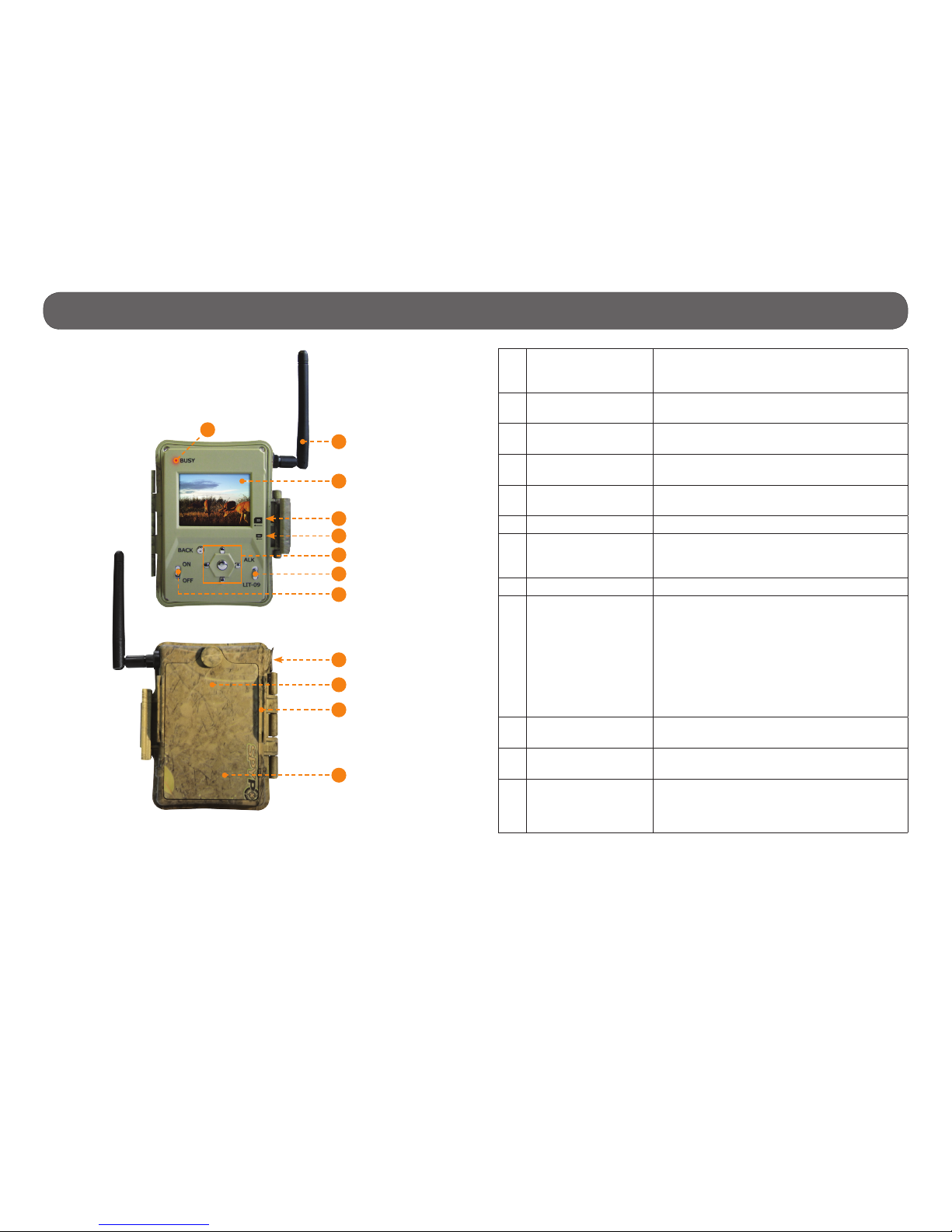
Components • Controller (BLACKBOX-4G)
1 BUSY LED Lights up when the controller records a le,
transfer photos or searches for the cellular
signal.
2 Antenna Allows wireless communication between the
controller and the camera(s).
3 Viewing screen Allows the user to access the main menu, see
battery level and view photos.
4 SD card slot An SD card is required to record photos
(p.16).
5 SIM card slot A SIM card is required for cellular functions
(p.16).
6 Navigation buttons Buttons to set the controller (p.28).
7 Battery switch Allows the user to select the power source
according to the type of batteries used
(p.12).
8 ON/OFF Allows the user to turn on/off the device.
9 1)12V power jack
2)Solar panel jack
1)The controller can be powered from an
external 12-volt DC input such as a 12V
battery or a 12V adapter, each sold
separately (p.44).
2)Allows the user to connect a solar panel
(SP-12V) to maintain the charge of the
lithium battery pack (LIT-09/LIT-C-8), sold
separately.
10 Battery case Case for AA batteries or a rechargeable lithium
battery pack (p.12).
11 Slot for installation
strap
Allows the user to install the controller using
the installation strap included (p.28).
12 Access to the time
battery
(located
inside the battery
case)
Battery that keeps the time and date in
memory (p.13).
9
10
11
12
2
1
3
4
5
6
7
8
10
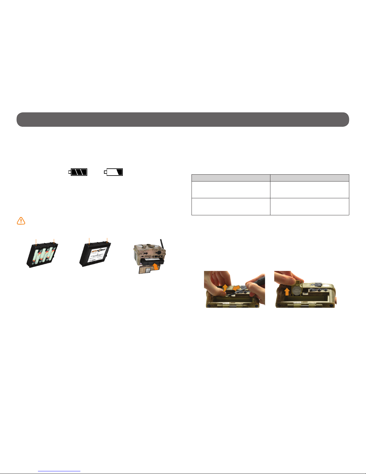
Power • Camera
The battery level is shown in the REPORT mode (4/4 = full, 1/4= low) and
in the bottom right corner of the screen when the camera is in TEST mode.
When the battery level shows 2/4 or when a single line remains (see gure
below), the camera will continue to take photos but we strongly recommend
to change the AA batteries or charge the lithium battery pack before they
are empty. If a video is being recorded and the batteries level reaches 0%,
the camera saves the le before shutting down.
AA BATTERIES
This camera requires 6 AA batteries (1.5V). The use of alkaline or lithium
batteries is strongly recommended. During the installation of the AA
batteries, slide the battery switch to ALK (i.e. alkaline). Insert the batteries
in the removable battery holder as indicated and insert it inside the camera
(see gure below). Battery polarity must be followed.
Please note that the voltage of rechargeable AA batteries (1.2V) is
insufcient to power the SPYPOINT camera. We also recommend the
use of new batteries to ensure maximum performance of the camera.
LITHIUM BATTERY PACK
This SPYPOINT camera can be powered by a rechargeable lithium battery
pack LIT-09/LIT-C-8 (sold separately, p.41). This type of battery is less
affected by cold temperatures and lasts up to 3 times longer than an alkaline batteries. During the installation of the lithium battery pack, slide the
battery switch to RECH. Insert the battery in the removable battery holder
and insert it inside the camera (see gures above).
EXTERNAL (12V)
This camera can also be powered by an external 12-volt DC input such as
a 12-volt battery (KIT-12V, BATT-12V or KIT6V/12V) or a 12-volt adapter
(AD-12V), each sold separately (p.41). During the installation of a 12-volt
connection, slide the battery switch to ALK (the AA batteries can remain
safely inside the camera). If combined with a lithium battery pack, slide the
battery switch to RECH. For available accessories, see p.41.
SOLAR PANEL
This camera also offers the possibility to connect a solar panel (SP-12V sold
separately, p.41) to maintain the charge of the lithium battery pack
(sold separately, p.41). While installing the rechargeable lithium battery
pack, slide the battery switch to RECH to activate the charging system of
the solar panel.
Battery switch position (depending on the power source)
Power source Battery switch position
• 6AA
• 12V
• 12V + 6AA
ALK
• LIT-09*
• 12V + LIT-09*
• Solar panel + LIT-09*
RECH
* Rechargeable lithium battery pack, sold separately (LIT-09) or with a
charger (LIT-C-8).
TIME BATTERY
The camera has a CR2032 lithium button battery which saves the time and
date. To replace the battery:
1. Turn off the camera and remove it from the housing.
2. Using a at screwdriver, push the tab to the left.
3. While pushing the tab to the left, remove the compartment of the camera.
4. Replace the battery, the polarity must be respected (side + facing up).
Insert connectors
rst
6 alkaline AA batteries
Lithium battery pack
LIT-09/LIT-C-8
Connectors
Connectors

11
Power • Receiver (BLACKBOX)
It is possible to know the battery level of the receiver when it is turned on.
The TEST LIGHT stays on for 8 seconds when the batteries are full. When
the TEST LIGHT ashes for 8 seconds, the batteries are low and need to be
replaced. If the TEST LIGHT remains off, the batteries are completely empty
or are possibly installed in the wrong direction.
AA BATTERIES
The receiver requires 6 AA batteries (1.5V). The use of
alkaline or lithium batteries is strongly recommended.
Insert the batteries as indicated, battery polarity must
be followed.
Please note that the voltage of rechargeable AA bat-
teries (1.2V) is insufcient to power the BLACKBOX
receiver. We also recommend the use of new batteries to
ensure maximum performance of your device.
EXTERNAL (12V)
The receiver can also be powered from an external 12-volt DC input such
as a 12-volt battery (KIT-12V, BATT-12V or KIT6V/12V) or a 12-volt adapter
(AD-12V), each sold separately (p.43). During the installation of a 12volt connection, the AA batteries can remain safely inside the receiver. For
available accessories, see p.43.
SOLAR PANEL
The receiver can be powered with a 12-volt battery combined with a solar
panel SP-12V (sold separately, p.43) to maintain the charge of the 12volt battery (sold separately, p.43).
6 alkaline AA
batteries
12
Power • Controller (BLACKBOX-D/BLACKBOX-4G)
The battery level is shown in the top right corner of the screen. When a
single line remains, the controller will continue to receive photos but we
strongly recommend to change the AA batteries or charge the lithium battery pack before they are empty.
AA BATTERIES
The controller requires 6 AA batteries (1.5V). The use of alkaline or lithium
batteries is strongly recommended. During the installation of the AA batteries, slide the battery switch to ALK (i.e. alkaline). Insert the batteries in the
compartment as indicated. Battery polarity must be followed.
Please note that the voltage of rechargeable AA batteries (1.2V) is
insufcient to power the controller. We also recommend the use of new
batteries to ensure maximum performance of your device.
LITHIUM BATTERY PACK
The controller can be powered by a rechargeable lithium battery pack LIT-
09/LIT-C-8 (sold separately, p.44). This type of battery is less affected by
cold temperatures and lasts up to 3 times longer than an alkaline batteries.
During the installation of the lithium battery pack, slide the battery switch
to LIT-09. Insert the lithium battery pack in the compartment as indicated.
EXTERNAL (12V)
The controller can also be powered by an external 12-volt DC input such as
a 12-volt battery (KIT-12V, BATT-12V or KIT6V/12V) or a 12-volt adapter
(AD-12V), each sold separately (p.44). During the installation of a 12-volt
connection, slide the battery switch to ALK (the AA batteries can remain
safely inside the controller). If combined with a lithium battery pack, slide
the battery switch to LIT-09. For available accessories, see p.44.
SOLAR PANEL
The controller also offers the possibility to connect a solar panel (SP-12V
sold separately, p.44) to maintain the charge of the lithium battery pack
(sold separately, p.44). While installing the rechargeable lithium battery
pack, slide the battery switch to LIT-09 to activate the charging system of
the solar panel.
Battery switch position (depending on the power source)
Power source Battery switch position
• 6AA
• 12V
• 12V + 6AA
ALK
• LIT-09*
• 12V + LIT-09*
• Solar panel + LIT-09*
LIT-09
* Rechargeable lithium battery pack, sold separately (LIT-09) or with a
charger (LIT-C-8).
6 alkaline AA batteries
Lithium battery pack
LIT-09/LIT-C-8

13
Power • Controller (BLACKBOX-D/BLACKBOX-4G)
TIME BATTERY
Located inside the battery case, the CR2032 lithium button battery saves
the time and date. To replace the battery:
1. Turn off the controller
2. Loose the screw located behind the controller to remove the cover of
the battery case.
3. Loose the screw at the bottom of the battery case to access to the time
battery.
4. Using a at screwdriver, push the battery upwards and lift to remove it
from its holder.
5. Replace the battery, the polarity must be respected (side + facing up).

14
Memory card/ "BUSY" LED/ Antenna • Camera
MEMORY CARD
A memory card is required to record photos and videos. The camera is
compatible with SD/SDHC memory cards, up to 32 GB capacity. (sold
separately, p.41).
When the PHOTO, VIDEO or TEST mode is selected and no memory card
is used, the screen displays "Insert memory card" and the camera beeps.
When the SD card is full, the screen displays "Memory card full".
Here is a table of the approximate number of photos and length of videos
that can be recorded with different memory card capacities. Many photo and
video resolutions are noted, see those corresponding to the camera.
4 GB 8 GB 16 GB 32 GB
Photo
3 MP 4100 8200 16400 32800
4 MP 3800 7600 15200 30400
5 MP 3400 6800 13600 27300
6 MP 3200 6300 12600 25300
7 MP 2700 5500 10900 21800
8 MP 2400 4800 9500 19000
10 MP 1900 3800 7600 15200
12 MP 1600 3200 6300 12600
Video
320 x 240 4 h 8 h 16 h 32 h
640 x 480 2h10 4h10 8h20 16h40
1280 x 720 40 min 1h20 2h40 5h20
INSERTING THE MEMORY CARD
Insert an SD/SDHC memory card (up to 32 GB
capacity) in the card slot, gold contacts facing up.
The card is inserted correctly when a click is heard.
Before inserting or removing a memory card,
always turn off the camera to prevent loss or
damage of the photos already recorded.
REMOVING THE MEMORY CARD
Lightly press the memory card into the camera once to pop it out of the slot
and remove it.
"BUSY" DEL
The "BUSY" light, located beside the screen, lights up when the camera
records a le.
ANTENNA INSTALLATION (TINY-PLUS)
Remove the cap and screw the antenna on the side
of the camera. The antenna allows wireless communication between the camera and a controller. The
TINY-PLUS camera can be added to the wireless system TINY-W3 (composed of a TINY-W3 camera and a
BLACKBOX-D controller) and to the wireless system
TINY4G (composed of a TINY4G camera and a BLACKBOX-4G controller). Up to 10 cameras can be com-
bined to a single controller.

15
Memory card • Receiver (BLACKBOX)
MEMORY CARD
A memory card is required to operate the BLACKBOX receiver. The receiver
is compatible with SD/SDHC memory cards, up to 32 GB capacity (sold separately, p.43).
When the memory card of the receiver is full, the transmission and recor-
ding of photos continue by clearing the rst recorded photos on the memory
card.
Here is a table of the approximate number of photos that can be recorded
with different memory card capacities.
INSERTING THE MEMORY CARD
Insert an SD/SDHC memory card (up to 32 GB capacity)
in the card slot, gold contacts facing up. The card is inserted correctly when a click is heard.
Before inserting or removing a memory card, always
turn off the receiver to prevent loss or damage of the
photos already recorded.
REMOVING THE MEMORY CARD
Lightly press the memory card into the receiver once to pop it out of the slot
and remove it.
4 GB 8 GB 16 GB 32 GB
Photo
3 MP 20500 41000 61500 82000
5 MP 17000 34000 51000 68000
8 MP 12000 24000 36000 48000

16
Memory card/ SIM card/ "BUSY" LED • Controller (BLACKBOX-D/BLACKBOX-4G)
MEMORY CARD
A memory card is required to operate the controller. The controller is
compatible with SD/SDHC memory cards, up to 32 GB capacity (sold
separately, p.44).
(BLACKBOX-D) When the controller’s memory card is full, the transmission
and recording of photos continue by clearing the rst recorded photos on
the memory card.
When the START BLACKBOX option is selected and no memory card is used,
the screen indicates to insert a memory card. The BLACKBOX-D controller
also beeps. When the SD card is full, the screen displays "Memory card full".
Here is a table of the approximate number of photos that can be recorded
with different memory card capacities.
4 GB 8 GB 16 GB 32 GB
Photo
3 MP 20500 41000 82000 164000
5 MP 17000 34000 68000 136500
10 MP 9500 19000 38000 76000
INSERTING THE MEMORY CARD
Insert a SD/SDHC memory card (up to 32 GB capacity) in the card slot. The
card is inserted correctly when a click is heard.
Before inserting or removing a memory card, always turn off the
controller to prevent loss or damage of the photos already recorded.
REMOVING THE MEMORY CARD
Lightly press the memory card into the controller once to pop it out of the
slot and remove it.
INSERTING THE SIM CARD
(BLACKBOX-4G)
Carefully insert a SIM card in the card slot, gold
contact area facing up.
Before inserting or removing a SIM card,
always turn off the controller.
REMOVING THE SIM CARD
(BLACKBOX-4G)
Use pliers to gently remove the SIM card from the controller.
«BUSY» DEL (BLACKBOX-D)
The «BUSY» light, located above the screen, lights up when the controller
records a le.
«BUSY» DEL (BLACKBOX-4G)
The «BUSY» light, located above the screen, lights up when the controller
records a le, transfer photos or searches for the cellular signal.
BLACKBOX-D BLACKBOX-4G
17
Settings • Camera
Use the and buttons to navigate in the interface and modify the selection,
the OK button to select and the button to return to the previous menu.
PHOTO
Allows the user to take photos. When the PHOTO mode is selected, the
test light in front of the camera will ash for 60 seconds to allow the user to
leave the area without being photographed.
VIDEO
Allows the user to take videos. When the VIDEO mode is selected, the
test light in front of the camera will ash for 60 seconds to allow the user to
leave the area without being recorded.
TEST
Allows the user to test the detection system of the camera. When
TEST mode is selected, no photo or video is recorded. Walk perpendicularly in front of the camera. When the camera detects a movement, the
light blinks to indicate that normally, a photo or video would have been
recorded. If the system does not detect the movement, increase the detection
distance using the "Sensitivity" option in the settings menu. Realign the
camera can also be required. In TEST mode, it is possible to take a photo by
pressing the OK button. The photo is saved and appears in the VIEW mode.
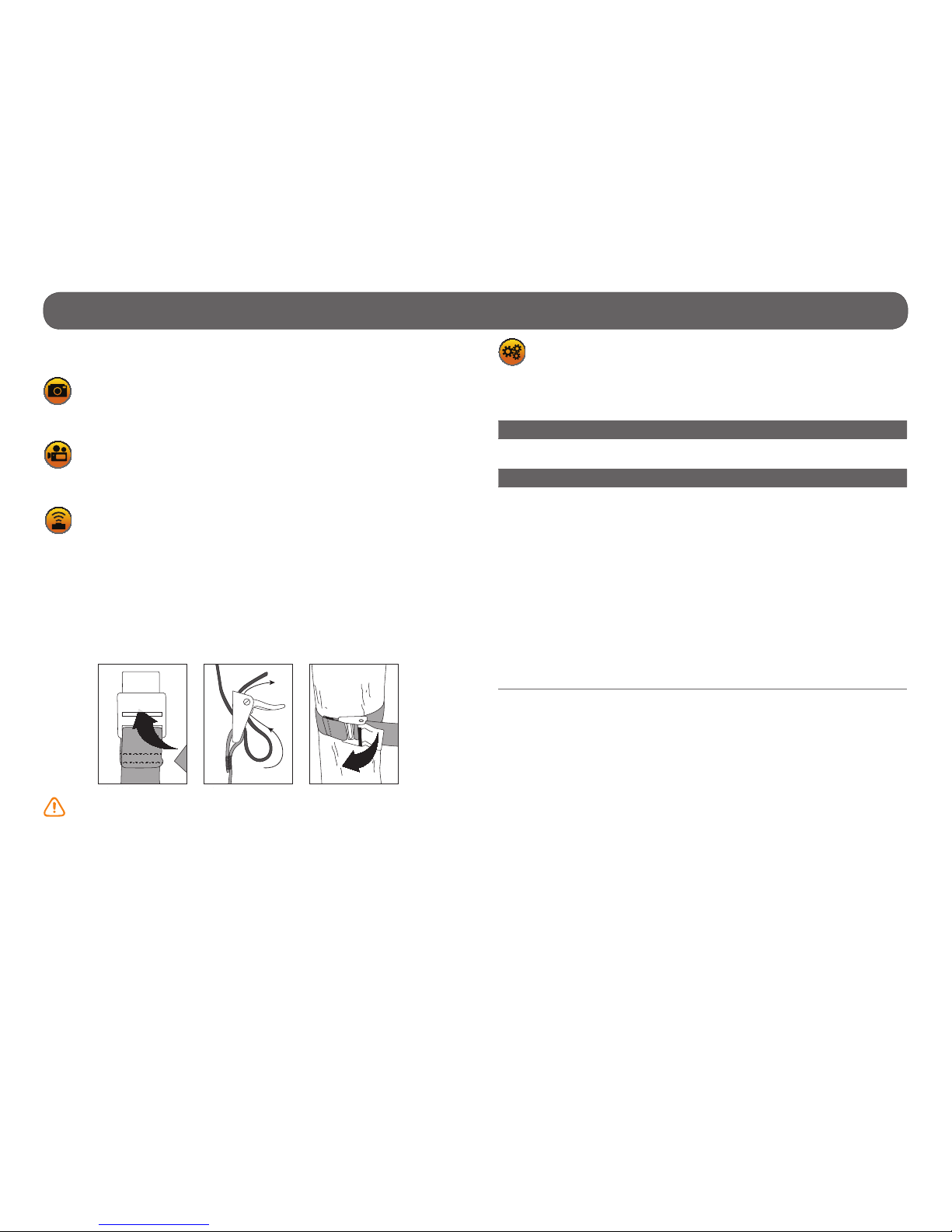
INSTALLATION WITH THE SUPPLIED STRAP
Recommended installation height: about 3 feet above the ground.
Do not place the camera facing the sun.
SETTINGS
Allows the user to change the different settings. To set the system in
English, hold the button until "Language" is highlighted. Press OK, select
"English" with the button or and conrm the choice with OK. The system
will then change the menus to English.
Camera ID: (TINY-PLUS, TINY-W
3
, TINY4G)
Allows the user to assign a name to the camera (maximum 8 characters).
Start time/Stop time:
Allows the user to set the operation period of the camera. The start and
stop time programmed hours are the hours during which the camera is in
action and records photos or videos. Example: If the user selects "15:00"
start time and "19:00" stop time, the camera will only detect for that
period of time and will stay inactive for the remaining hours. Press OK
and use or to adjust the hours. Press OK again to set the minutes.
When the time is properly set, press OK.
For a 24 hour activation, the same start and stop times must be entered
(example: 00:00 as start time and 00:00 as stop time. These hours are
the basic settings of the camera.
Note: The hours are recorded over a 24-hour period. For example, 5pm
is 17:00 (00:00 means midnight).

18
Settings • Camera
Wireless: (TINY-PLUS, TINY-W
BF
, TINY-W3, TINY4G)
(On/Off)
Enables or disables the wireless transmission of photos to the BLACKBOX
receiver (TINY-WBF), to the BLACKBOX-D controller (TINY-PLUS, TINY-W3)
or to the BLACKBOX-4G controller (TINY-PLUS, TINY4G).
When the transmission is enabled:
• Only photos are transmitted to the receiver and to the controller, not
videos.
• The quality of the photos recorded on the receiver and the controller is
reduced to maximize transmission:
8 or 10MP = 800 x 600 pixels
5MP = 640 x 480 pixels
3MP = 320 x 240 pixels
• When the TIME LAPSE mode is enabled, the photos are sent to the
receiver and to the controller except for the "30s" setting.
• When the delay setting "10s" is selected, the time between each
detection is calculated when the transmission is completed. For
example, if the transmission takes two seconds, the time between the
two detections is 12 seconds.
Note: When the "Wireless" option is activated, it is only possible to take up
to 2 consecutive shots
(TINY-PLUS, TINY-W3, TINY4G).
Delay:
(10s/1m/3m/5m/10m/15m/30m)
Allows the user to choose the time interval between each detection before
the camera records the next photo or video. A longer delay minimize the
number of photos taken and maximize the battery life. A shorter delay
maximize the number of photos taken but requires more battery power.
The shorter times interval are recommended when the cameras is used
for security purposes.
Additional setting:
It is possible to decrease the delay between detections to 10 seconds
(instead of 1 minute) by using the following procedure.
Note that the battery life will be affected.
1. Turn OFF the camera.
2. Press and hold the button and turn ON the camera.
3. "10sec enabled" appears on the screen meaning the minimum delay is
now 10 seconds. If this option is used, the 30 minute delay disappears.
4. To reset the camera to 1 minute delay, follow the same procedure.
"10sec disabled" appears on the screen. (see next gure)
Multi-shot:
(1/2/3/4/5/6 consecutive shots)
Takes up to 6 consecutive shots at each detection, with a 10-second delay
between each photo. This option allows the user to get up to 6 photos
from different angles when the camera is in PHOTO mode.
Note: When the "Wireless" option is activated, it is only possible to take up
to 2 consecutive shots (TINY-PLUS, TINY-W
3
, TINY4G).
Video length:
(10s/30s/60s/90s)
Allows the user to select the duration of the recording when the camera
is set in VIDEO mode.
Language:
(English/Français/Deutsch/Italiano/Español)
Allows the user to select a language for the camera menus.
P INTSPY INTPSPY
10SEC DISABLED
P INTSPY INTPSPY
10SEC ENABLED
P INTSPY INTPSPY
10SEC DISABLED
10 s delay 1 min delay

19
Settings • Camera
Sensitivity:
(Low/Medium/High)
Allows the user to choose the detection sensitivity of the camera. A higher
sensitivity allows the user to take more photos.
The camera will only detect sources of heat in movement. Make sure to
have the least possible objects in front of the camera during the positioning. This prevents the camera to take photos when oriented towards the
sun while an object moves in front of the camera (e.g. a branch).
Date:
Allows the user to set the date as Month/Day/Year.
Time format:
(12h/24h)
Allows the user to select the time display over a period of 12 or 24 hours
on the photos. (e.g. 6:00 pm or 18:00)
Time:
Allows the user to set the time as Hour/Minute.
Stamp:
(Yes/No)
Allows the user to have date, time, temperature and moon phases printed
on the photos.
New moon:
Waxing Crescent:
First Quarter:
Waxing Gibbous:
Full moon:
Waning Gibbous:
Last Quarter:
Waning crescent:
Quality:
(Low/Medium/High)
Allows the user to set the photo resolution. The low resolution allows the
user to save space on the card and the high resolution allows the user to
get a better photo quality.
When the quality is set to "High", the video resolution is automatically
set to 1280 x 720 or 640 x 480 (TINY-WBF) and when is set to "Medium"
or "Low", the video resolution is automatically set to 640 x 480 or 320 x
240 (TINY-WBF).
Temperature:
(°C/°F)
Allows the user to select the temperature display.
Continuous:
(Yes/No)
Allows the user to take photos or videos even if the memory card is full.
The camera will continue to record photos or videos by deleting the rst
recorded les.
Power
(TINY-4G):
(Batteries/Electricity)
Allows the user to select the type of power supply.
Choose "Electricity" if the camera is powered by a main electric power
supply (using a 12-volt DC adapter, #AD-12V, sold separately (p.41).
A main electric power supply is recommended when camera is used for
security purposes. It provides an instant trigger time when a movement is
detected. The lithium battery pack and the AA batteries can remain safely
inside the camera and it is ideal for blackouts. A 12-volt DC adapter that
can provide a minimum of 800 mA is required (p.41).
Note: When using a main electric power supply, the MULTI-SHOT mode
and the DELAY option are disabled as the camera triggers instantly every
time it detects motion. Also, the printing of the temperature on each
photo is disabled.

20
Settings • Camera
Time lapse:
(Off/30s/1m/3m/5m/15m/30m/1h)
Allows the camera to take photos at regular preset intervals. For example,
if the option "5m" is selected in the TIME LAPSE mode, the camera takes
a photo every 5 minutes during the period of operation (start time and
stop time) even if there is no detection. This option allows the user to
obtain photos of game outside the detection range of the camera.
Note: The TIME LAPSE mode only applies in PHOTO mode, not in VIDEO
mode. When TIME LAPSE mode is selected, the DELAY option and the
MULTI-SHOT mode are disabled.
Remote control (RC-1):
(TINY4G)
(On/Off)
Allows the user to use the RC-1 remote control which works with the
REMOS wireless technology (sold separately, p.41). The remote control
allows to activate/deactivate the detection of the camera, to remotely
take a photo/video in an area of 500 ft and to activate the buzzer signal
on the BLACKBOX-4G controller in an area of 500ft.
Wireless sensor (MS-1):
(TINY4G)
(Off/1/2/3/4/5/6/7)
Allows the camera to be triggered wirelessly by one or more MS-1 devices
through the REMOS wireless technology, sold separately (p.42).
IR-Booster:
(TINY4G)
(On/Off)
Allows the camera to trigger, up to a distance of 50ft, one or more IR-
BOOSTER infrared lighting devices without the use of an additional transmitter through the REMOS wireless technology. Sold separately, p.42.
Infrared:
(On/One LED/Off)
Allows the user to choose the desired infrared lighting.
On: All LEDs work when taking photos or videos at night.
One LED: Only a single LED works
(see gure). This option can be useful when using an IR-Booster/Invisible
LEDs IR-Booster (sold separately,
p.42).
Off: LEDs are deactivated so your night photos or videos are black.
Side sensors:
(On/Off)
When the side sensors are activated, a total of 7 zones are covered. The
central sensor covers 5 zones. The side detectors are mainly used to prepare the camera so when your target passes through the central sensor,
the system is already pre-triggered, increasing greatly the reaction time
of your camera (ideal when the camera is placed near a narrow trail).
The side sensors require more battery power.
34’
30’
65’
30° 70°40°
S
C
S
Camera
Detection distance (central)
Detection distance
of the side sensors
s: Side sensors
c: Central sensor
: Detection zone
: Viewing field
30°: Detection angle of the central sensor
40°: Viewing angle for TINY series cameras
70°: Detection angle including both
central and side sensors (2)
LED for
infrared
sensor

21
Settings • Camera
REPORT
The report mode keeps a record of the last period of use of the camera
and indicates the battery level (4/4=full). The beginning date corresponds
with the moment the camera is set to either PHOTO or VIDEO mode. Thus,
the report is reset when changing modes.
1.
2.
3.
4.
5.
6.
7.
8.
9.
1. Beginning and end date of the report
2. Number of photos or videos taken during the day
3. Number of photos or videos taken at night
4. Total of photos or videos taken
5. Current time of the camera
6. Current date of the camera
7. Battery level (1/4 = low, 4/4 = full)
8. Remaining space on the SD card estimated by a number of photos
9. Used space on the SD card (total number of les, only includes photos
and videos taken by a SPYPOINT camera)
VIEW
Allows the user to view or delete recorded photos and videos on the
camera screen or on a television.
• Viewing with the screen of the camera:
When the VIEW mode is selected, the latest photo or video recorded appears
on the screen automatically. Press or to view next or previous images.
Press OK to view the different options available.
Play: Allows the user to play or pause the video on the screen.
(This option is available only for videos)
Date and time: Allows the user to view the date and time printed on
the photo.
Protect: Allows the user to protect a photo or video to prevent it
from being deleted by selecting "Delete All".
Delete: Allows the user to erase from the memory card, the
photo or the video seen on the screen.
Delete all: Allows the user to erase from the memory card all stored
photos and videos, with the exception of protected les.
Format: Allows the user to format memory card and delete all
protected photos and videos.
Exit: Allows the user to exit the menu to return to the viewing
screen.
• Watching on TV:
Allows the user to view or delete the photos or videos directly on a TV.
1. Turn on the camera.
2. Connect the yellow end of the RCA cable supplied into the VIDEO IN of
the TV and the other end into the TV OUT of the camera. The options
are the same as viewing on the screen of the camera (previously mentioned).
SIGNAL
(TINY-PLUS, TINY-WBF, TINY-W3, TINY4G)
Allows the user to test the wireless signal and to synchronize the
camera with BLACKBOX systems. See p.23 and p.25 for more details.
RCA
Note: The number of yellow stars that appear to the right of the screen
corresponds to the resolution of the photos.
=Low resolution =Medium resolution =High resolution

22
REMOS Technology • Camera
REMOS TECHNOLOGY (TINY
4G
)
The cameras compatible with the REMOS technology (wireless functionnalities) can be combined with:
• RC-1 :Remote control
Allows the user to control the camera remotely.
• MS-1 :Motion sensor
Allows the user to trigger the camera remotely.
• IRB-W-B : Infrared Booster
Used to optimize the infrared lighting to accentuate the quality of night
photos and videos.
See SETTINGS (p.17) and AVAILABLE ACCESSORIES (p.41) sections
for more details.
The optional steel security box (SB-T) affects the wireless functio-
nalites of products compatible with REMOS technology. The wireless
transmission of photos from the cameras TINY4G to the controller is also
affected.

23
Setup • Receiver (BLACKBOX)
By default, the TINY-WBF camera is synchronized with its receiver on
channel 1 and the icon SYNC is green. (see SIGNAL mode in menu)
To change the synchronization channel or to add other sets (TINY-WBF
camera/BLACKBOX receiver) in the same area, refer to the MANUALLY SYNCHRONIZING ONE OR MULTIPLE SETS IN THE SAME PERIMETER section
(p.24).
INSTALLATION OF THE RECEIVER AND THE CAMERA
The strength of the wireless signal varies depending on the orientation of
the receiver. We strongly recommend installing the receiver on the same
side of the antenna of the camera (see gure below).
For best results, the antennas of the two devices must also point upwards
and their respective height should be approximately the same (see gure
below).
Sync
Channel
1
+
TREE
SIGNAL STRENGHT
SIGNAL
STRENGHT
INSTALLATION WITH THE SUPPLIED STRAP
WIRELESS SIGNAL TEST
The quality of the wireless signal between the TINY-WBF camera and the
BLACKBOX receiver can be checked on the camera. Perform the range test
after the nal installation of the devices. To see the wireless signal icon on
the main menu, the WIRELESS option in Settings should be on.
1-Select the SIGNAL mode.
2-Select the Range test option.
Range Test
If the icon of the wireless signal is red, the signal is too weak. Move the
receiver or bring it closer. If the icon of the wireless signal is green and stays
green for at least 10 seconds, the signal is strong and stable enough to
enable wireless transmission of photos to the receiver.
Note: If the receiver is turn off and not synchronized with the camera, the
signal icon remains red.

24
Setup • Receiver (BLACKBOX)
Note: In the minute following turning on the receiver, the test light of the
receiver ashes. The rst 8 seconds allows the user to know the battery
status (p.11). Then for the rest of the time, the test light ashes rapidly
to indicate the synchronization period.
Note: After a synchronization or when the test light turns off (after 60
seconds), the receiver can’t be synchronized unless it is turned off and
on again.
MANUALLY SYNCHRONIZING ONE OR MULTIPLE SETS (TINY-W
BF
CAMERA/BLACKBOX RECEIVER) IN THE SAME PERIMETER
To change the synchronization channel or to install one or many sets
(TINY-W
BF
/BLACKBOX receiver) in the same area of transmission, it is
necessary to manually synchronize each camera with its receiver on a
different channel.
1. Turn on the rst camera and choose the SIGNAL mode.
2. Turn on the rst BLACKBOX receiver.
3. Choose the
Channel
1
option on the camera and press OK.
4. Use the and buttons to select a channel and press OK.
5. Choose the
Sync
option on the camera and press OK.
6. The camera synchronizes with the powered receiver and the
icon Sync goes from red to green when the synchronization
is complete.
7. Turn off the camera and the corresponding receiver.
8. Repeat these steps for each additional set, up to 9 sets (TINY-W
BF
/BLACK-
BOX
receiver) can be matched in a same perimeter of 250ft.
Sync

25
MAIN MENU
Use the and buttons to navigate in the interface and to modify the
selection. Use the OK button to select and the BACK button to return to the
previous menu.
SIGNAL
Allows the user to synchronize a new camera to a BLACKBOX-D controller, see SYNCHRONIZE A NEW CAMERA TO THE CONTROLLER section
(p.27). Also allows to add other sets (camera/BLACKBOX-D) in a same
area, see USING MULTIPLE CONTROLLERS IN THE SAME AREA section
(p.27).
By default the TINY-W3 camera, supplied with the BLACKBOX-D, is already
synchronized to the controller as CAMERA 01 in groupe 1 and the camera
icon is green. Each additional camera (TINY-PLUS) must be synchronized
with the BLACKBOX-D. To see the wireless signal icon on the main menu,
the WIRELESS option in SETTINGS should be on.
START BLACKBOX-D
Select this option when the controller and camera(s) have been con-
gured and synchronized. The controller is now ready to receive photos
from the synchronized camera(s).
SETTINGS
Allows the user to congure the different parameters of the synchronized cameras.
1. When SETTINGS is selected, the complete list of options in the menu is
displayed. If more than one camera is synchronized to the controller,
choose the one that is to be changed.
2. Make the desired changes and press OK to conrm.
3. Press the BACK button to send the new parameters to the camera.
4. The message "Sending Settings" appears on the screen of the BLACK
BOX-D and the screen of the camera shows "Receiving". The controller
returns to the main menu when the changes are successful.
Setup • Controller (BLACKBOX-D)
BLACKBOX-D AND CAMERA INSTALLATION
The strength of the wireless signal varies depending on the orientation of
the controller. We strongly recommend installing the controller on the same
side of the camera’s antenna (see gure below).
For best results, the antennas of the two devices must also point upwards
and their respective height should be approximately the same (see gure
below).
INSTALLATION WITH THE SUPPLIED STRAP
TREE
SIGNAL STRENGHT
SIGNAL
STRENGHT
Note: When the controller is left inactive for more than 2 minutes on the
main menu, it automatically resets itself to "START BLACKBOX" mode.
To return to the main screen, turn off the controller and turn it on again.
Note: When this option is selected, the controller screen turns off in order
to preserve battery life. To return to the main screen, turn off the controller and turn it on again.

26
VIEW
Allows the user to view or delete the recorded photos on the controller
screen or on a television.
• Viewing with the screen of the controller:
When VIEW mode is selected, choose the name of the desired camera and
press OK. The last recorded photo automatically appears on the screen.
Press f or g to view the next or previous. Press OK to view the different
options available.
Date and time: To view the date and time printed on the photo.
Protect: Allows the user to protect the photo to prevent it from
being deleted by selecting "Delete All".
Delete: Allows the user to erase from the memory card, the
photo seen on the screen.
Delete all: Allows the user to erase from the memory card, all
stored photos, with the exception of protected photos.
Format: Allows the user to format memory card and delete all
protected photos.
Exit: Allows the user to exit the menu to return to the viewing
screen.
Press the to enlarge the photo on the screen or to return to the original
size. When the photo is enlarged, press OK to allow movement in the photo.
Then use the navigation buttons to explore different parts of the photo. To
disable the mouvement mode, press OK again.
Setup • Controller (BLACKBOX-D)
REMOTE
Allows the user to see the camera status, to start/stop the camera, to
verify the quality of the wireless signal and to have an overview of the eld
of view of the camera in real time. If more than one camera is synchronized
to the controller, choose one from those available.
Get camera status
Indicates the battery level and the percentage of used space in the memory
card of the camera.
Start/stop caméra
Allows the user to remotely stop or restart photos taking. These options can
be used if the user is working in the zone of detection of the camera and he
doesn’t want photos to be taken. When nished, he can remotely restart the
camera to continue taking photos.
Range test
Allows the user to check the quality of the wireless signal between the camera and the controller. If the icon of the wireless signal is red, the
signal is too weak. Bring closer or move the controller. If the icon
of the wireless signal is green and stays green for more than 10
seconds, the signal is strong enough and stable to enable wireless transmission of photos to the controller.
Live view
Allows a live preview of the eld of view of the camera in real time (1 photo
per second is sent to the controller). Press the BACK button to return to the
previous menu.
This mode requires more battery power.
Note: The message "Waiting for camera" appears on the screen of the
BLACKBOX-D if the controller is not synchronized with the camera or if the
wrong camera ID is selected.
Note: The preview can also be on a TV using the TV-OUT port of the
controller (see View section, p.26).
Note: The number of yellow stars that appear to the right of the screen
corresponds to the resolution of the photos stored in the BLACKBOX-D.
=Low résolution =Medium résolution =High résolution

27
USING MULTIPLE CONTROLLERS IN THE SAME AREA:
When multiple controllers are installed in the same area of transmission, it
is necessary to manually synchronize each controller with it’s camera(s) in
a different group.
To do this:
1. On the controller, select the SIGNAL mode
and press OK.
2. Hold down the button for 3 seconds to reach the group option located
in the upper right corner of the screen controller and press OK.
3. Use or buttons to assign a new group to each additional controller
(maximum 5 BLACKBOX-D) and press OK.
4. Synchronize the cameras to the new group (follow the steps in the
PREPARING THE CAMERA (P.27) and PREPARING THE BLACKBOX-D
CONTROLLER (p.27) sections.
Setup • Controller (BLACKBOX-D)
• Watching on TV:
Allows the user to view or delete the photos directly on a TV.
1. Turn on the controller.
2. Connect the yellow end of the RCA cable supplied into the VIDEO IN of
the TV and the other end into the TV OUT of the controller. The options
are the same as viewing on the screen of the controller (previously
mentioned)
SYNCHRONIZE A NEW CAMERA TO THE CONTROLLER:
Preparing the camera:
1. Set the name of the camera:
• When SETTINGS is selected, choose "Camera ID" and press OK.
• Determine the name of the camera by pressing the or buttons to
change the letter and press OK to go to the next space.
2. Continue changing other parameters of the camera as needed.
3. To enable communication with the controller:
• While still in the SETTINGS menu, select "Wireless" option and press
OK.
• Select "On" and conrm the selection by pressing OK; then on BACK to
return to the previous menu.
4. Select the SIGNAL mode
and press OK. The camera searches for the
controller.
Preparing the BLACKBOX-D controller:
1. Select the SIGNAL mode
.
2. Press on "Add new camera" (to see this option, select a blue camera icon
using f or g buttons. The "Sync" icon changes from
red to green in the camera screen when synchronization is
successful.
Note: A camera cannot be synchronized to multiple controllers.
RCA
Notes:
• It’s possible to synchronize up to 10 cameras to a single controller.
• If the name of the camera is changed, it is necessary to resynchronize
the devices by following the steps in the PREPARING THE CAMERA
(P.27) and PREPARING THE CONTROLLER (p.27) sections.
• The "Reset All" option allows to nd the original settings.
• It is possible to easily retrace the BLACKBOX-D controller with a buzzer
signal by pressing the FN button on the RC-1 remote control. The remote
control must be previously synchronized with the camera, which commu nicates with the controller. The remote control (sold separately, p.41)
is part of the product line compatible with the REMOS technology.
Sync

28
Power • Controller (BLACKBOX-4G)
CONTROLLER AND CAMERA INSTALLATION
The strength of the wireless signal varies depending on the orientation of
the controller. We strongly recommend installing the controller on the same
side of the camera’s antenna (see gure below).
For best results, the antennas of the two devices must also point upwards
and their respective height should be approximately the same (see gure
below).
INSTALLATION WITH THE SUPPLIED STRAP
TREE
SIGNAL STRENGHT
SIGNAL
STRENGHT
MAIN MENU
Use the and buttons to navigate in the interface and to modify the
selection. Use the OK button to select and the BACK button to return to the
previous menu.
START BLACKBOX
Select this option when the controller and camera(s) have been
congured and synchronized. The controller is now ready to receive photos
from the synchronized camera(s).
SETTINGS
Allows the user to change the different settings of the controller. To
set the system to English, press the or buttons until "Language" is high-
lighted. Press OK, select "English" with the or buttons and conrm the
choice with OK. The system will then change the menus to English.
The settings menu is presented as an interactive menu. By selecting
certain options, it allows the display of other options.
Language:
(English/Français)
Allows the user to select a language for the controller menus.
Auto time:
(Yes/No)
The date and time are synchronized with the cellular network when available and that the controller is set in CELLULAR mode.
When this option is disabled, the "Date" and "Time" options appear.
Date:
Allows the user to set the date as Year/Month/Day.
Time:
Allows the user to set the time as Hour/Minute/Second.
Note: When this option is selected, the controller screen turns off in order
to preserve battery life. To return to the main screen, turn off the controller and turn it on again.

29
Power • Controller (BLACKBOX-4G)
Time format:
(12h/24h)
Allows the user to select the time display over a period of 12 or 24 hours
on the photos (e.g. 6:00 pm or 18:00).
Camera mode:
(Standalone/Cellular)
Allows the user to select the operating mode of the controller.
When the Standalone mode is activated:
The controller receives the photos from the camera and saves it on its
memory card.
When the Cellular mode is activated:
The controller receives the photos of the camera, saves it on its memory
card and sends them to the mySPYPOINT server (subscription required)
in the user account according to the number of synchronization selected
(see Transmission mode option).
The controller works with HSPA+ cellular network. A cell phone
plan is required from a cellular service provider and must be
compatible with this network. The coverage area of the service
provider must also support the area where the TINY4G and the
controller will be used.
When the Cellular mode is selected, the "Auto time", "Country",
"Carrier" and "Transmission mode" options appears.
Note: In Cellular mode, it is recommended to use an external 12 volt power source (BATT-12/KIT6V-12V/KIT-12V/AD-12V, sold
separately) in order to get best results and longer battery life. See
POWER section for more details (p.44).
Country
Allows the user to select the country in which the controller is used. This
option displays a list of matching cellular providers.
Carrier:
This parameter must be correspond with the service provider of the user.
Choose in the list of supported providers the one that corresponds to the
SIM card used in the controller.
Transmission mode:
Allows the user to congure options for the transmission of photos to a
mySPYPOINT account (subscription required).
1. Synchronize (Permanent/1/2/6/12 times per day):
Allows the user to choose the number of synchronizations that the controller performs per day. This sets the frequency at which the controller communicates with the mySPYPOINT server to update its status or to send
photos to the user's account.
When set to "Permanent", it requires more battery power.
2. Synchronize:
Allows the user to choose at what time of the day that the controller
performs its initial synchronization with the mySPYPOINT server.
E.g.: If the option "Synchronize" is set to 6/day and "Synchronize at" at
04:00, the controller performs 6 synchronizations per day and starts sending rst at 4 h, 8 h, 12 h, 16 h, 20 h and 24 h.
3. Device informations including the serial number (#SN), the SIM card
number (#SIM) and the version number of the software. It may take few
seconds before the information is displayed. The BLACKBOX-4G should
also be in cellular mode.
Synchronize 1/Day
Synchronize at 00:00
#SN: 0000000
#IMEI: 0000000...
#SIM: 0000000...
Version: v0.1
2
1
3

30
Power • Controller (BLACKBOX-4G)
MANAGE CAMERAS
Allows the user to access to the list of options to manage the cameras
synchronized to the controller.
If more than one camera is synchronized to the controller, choose the one
that is to be changed with the f and g buttons. To reach the group option
in the upper right corner of the controller screen, hold the g button for 3
seconds. Change group with the and buttons and press the OK button to
return to the options. The group option allows user to regroup one or many
cameras to a controller when multiple controllers are installed in the same
transmission area.
Resync
Allows the user to synchronize a new camera to the BLACKBOX-4G controller
(p.31). By default the TINY4G camera, supplied with the BLACKBOX-4G, is
already synchronized to the controller as CAMERA01 in groupe 1. Each additional camera (TINY-PLUS) must be synchronized with the BLACKBOX-4G
(p.31).
Settings
Allows the user to congure the differents settings of the synchronized
cameras. See the SETTINGS • Camera section (p.17) for more details
concerning each setting.
When all desired changes are completed, press the BACK button to send
the new settings to the camera. The message "Update settings to camera?"
appears on the BLACKBOX-4G screen and select "Yes". The screen of the
camera indicates "Receiving". The controller returns to the main menu when
the changes were completed.
Get camera status
Indicates the battery level and the percentage of used space in the memory
card of the camera.
Start/stop camera
Allows the user to remotely stop or restart photos taking. These options can
be used if the user is working in the zone of detection of the camera and he
doesn’t want photos to be taken. When nished, he can remotely start the
camera to continue taking photos.
Range test
If the icon of the wireless signal appears green and stays green for more
than 10 seconds, the signal is strong enough and stable to enable wireless
transmission of photos to the controller. Press BACK (controller)
to return to the menu. If the icon of the wireless signal is red,
the signal is too weak. Bring closer or move the controller. Make
sure that the controller has been synchronized with the selected
camera.
VIEW
Allows the user to view or delete the recorded photos on the controller
screen.
When VIEW mode is selected, choose the name of the desired camera and
press OK. The last recorded photo automatically appears on the screen.
Press f or g to view the next or previous. Press OK to view the different
options available.
Delete: Allows the user to erase from the memory card the pho-
to seen on the screen.
Delete All: Allows the user to erase from the memory card all
stored photos.

31
Power • Controller (BLACKBOX-4G)
SYNCHRONIZE A NEW CAMERA TO THE CONTROLLER:
Preparing the camera:
1. Set the name of the camera:
• In the SETTINGS menu, choose the "Camera ID" option and press OK.
• Determine the name of the camera by pressing the or buttons to
change the letter and press OK to go to the next space.
2. Continue changing other parameters of the camera as needed.
3. To enable communication with the controller:
• Still in the SETTINGS menu, select the "Wireless" option and press OK.
• Select "On" and conrm the selection by pressing OK; then on BACK to
return to the previous menu.
4. Select the SIGNAL mode
and press OK. The camera searches for the
controller.
Preparing the BLACKBOX-4G controller:
1. In the MANAGE CAMERAS menu, select the "Resync" option and press
OK.
2. A green checkmark will appear next to the "Resync" option to indicate
that the synchronization is successful. The name of the camera appears
at the top of the options.
USING MULTIPLE CONTROLLERS IN THE SAME AREA:
When multiple controllers are installed in the same area of transmission, it
is necessary to manually synchronize each controller with its camera(s) in
a different group.
To do this:
1. On the controller, select the MANAGE CAMERAS menu and press OK.
2. Hold down the button for 3 seconds to reach the group option located in
the upper right corner of the screen controller.
3. Use the or buttons to assign a new group to each additional controller
(maximum 5 BLACKBOX-4G) and press OK.
4. Synchronize the cameras to the new group (follow the steps in the
PREPARING THE CAMERA (p.31) and PREPARING THE BLACKBOX-4G
CONTROLLER (p.31) sections).
Notes:
• It’s possible to synchronize up to 10 cameras to a single controller.
• If the name of the camera is changed, it is necessary to resynchronize
the devices by following the steps in the PREPARING THE CAMERA (p.31)
and PREPARING THE CONTROLLER (p.31) sections.
Note: A camera cannot be synchronized to multiple controllers.
Group 1
CAMERA01
Re Sync
Settings
Get Camera Status
Start Camera
Stop Camera
Range Test
√
Tip: Use a name that makes it easy to identify the camera
(e.g. : cottage front, house backyard, etc.).

32
Power • Controller (BLACKBOX-4G)
USE THE CELLULAR FUNCTIONS OF THE CONTROLLER
The controller communicates with the mySPYPOINT server to update its status or to send photos to the user account.
To do this:
1. The camera must be synchronized beforehand with the controller
(follow the steps in the PREPARING THE CAMERA (p.31) and PREPARING
THE BLACKBOX-4G CONTROLLER (p.31) sections).
2. The controller must be in CELLULAR mode (Settings
Camera Mode
Cellular).
3. Then, set the COUNTRY and CARRIER options.
4. In the TRANSMISSION MODE option (Settings Transmission Mode),
set the SYNCHRONIZE et SYNCHRONIZE AT options.
5. Return to the main menu. The controller immediately searches for the
cellular signal. Make sure you have a cellular signal.
6. The controller is ready to receive photos from the camera and send it to a
mySPYPOINT account. Select START BLACKBOX.
Start BlackBox
Settings
Manage Cameras
View
Truphone 4G
Note: It's preferable to install the controller outside to facilitate the cel-
lular signal reception.

33
Sound recording/ External triggering • Camera
SOUND RECORDING
The SPYPOINT camera offers the possibility to record sound in VIDEO
mode. When the VIDEO mode is selected, the camera automatically re-
cords the sound. Under the camera, you will nd a rubber cap with the
inscription MIC. If the user does not want to record the sound, the rubber
cap needs to stay in place. If sound recording is required, the user must
lift the rubber cap and turn it slightly so that the microphone receiver is
completely cleared (See gure below).
EXTERNAL TRIGGERING
1/8" input which triggers the taking of photos or videos using a normally
open contact.
Example: Using a magnetic door contact connected to an alarm system (see
gure below). 1/8" Mono connector not included.
Weld the two wires of a
door contact to a 1/8"
mono connector.
Insert the connector in the
external trigger jack of the
camera.

34
File transfer to a computer • Camera
To transfer photos/videos to a computer:
1. Turn OFF the camera.
2. Connect the USB cable (supplied) from the camera to a computer
3. The computer will detect the camera and install the driver automatically.
4. Click on "My Computer" and select "Removable Disk".
5. Then click on "DCIM" and "100DSCIM" to nd all your photos and videos.
6. Drag or save the les to the desired location.
Taking the memory card (sold separately, p.41) out of the camera and
inserting it into the computer slot will achieve the same results.
Note: Videos in .MP4 format require the use of a compatible video player
software such as VLC, Windows Media Player or QuickTime.
USB

35
File transfer to a computer •
Receiver
(BLACKBOX)/ Controller (BLACKBOX-D/BLACKBOX-4G)
To transfer photos to a computer, remove the memory card (sold separately,
p.43) out of the receiver or the controller and insert it into the computer
slot.
1. Click on "My Computer" and select "Removable Disk".
2. Then click on "DCIM" and "100DSCIM" to nd all the recorded photos.
3. Drag or save the les to the desired location.
The names of the photos recorded by the camera and the BLACKBOX-D/
BLACKBOX-4G controllers start by PICT while those stored in the BLACKBOX receiver starts by PICW. The BLACKBOX-D/BLACKBOX-4G controllers
create a folder for each synchronized camera and automatically class photos
to different folder.
MEMORY CARD

36
Troubleshooting • Camera
Problem Possible solutions
Impossible to
turn on the
camera
• Verify if there are batteries in the camera.
• Verify if the batteries are correctly installed (p.10).
• Verify if the battery switch position is positioned
according to the power source (p.10).
• Install the latest update (available on www.spypoint.
com under SUPPORT section).
• Replace alkaline batteries or recharge the lithium
battery pack.
The screen of the
camera turns off
• The camera may be set to PHOTO or VIDEO mode
and the screen turns off after a period of 60 seconds
in order to preserve battery life.
• The camera automatically resets itself to PHOTO or
VIDEO mode (depending of the latest mode used
or selected) after 2 minutes of inactivity on the main
menu.
• To return to the screen, turn off the camera and turn
it on again.
The camera beeps • Insert a memory card (p.14).
The camera does
not respond
• Remove the batteries and reinstall them (p.10).
• Replace alkaline batteries or recharge the lithium
battery pack.
The camera
works, but is
losing its time
and date settings
• The time battery must be replaced (p.10).
Impossible to
take photos/
videos
• Verify if there are batteries in the camera.
• Replace alkaline batteries or recharge the lithium
battery pack.
• Memory card is full.
• Verify if the camera is turned on.
No person/animal
on photos
• Sunrise or sunset can trigger the sensor. Camera
must be re-orientated.
• At night, the motion detector may detect beyond the
range of the IR illumination. Reduce sensibility
setting (p.19).
• Small animals may trigger the unit. Reduce sensibi lity setting (p.19) and/or raise height of camera.
• Motion detector may detect animals through foliage.
• If a person or animal moves quickly, it may move out
of the camera’s eld of view before the photo is
taken. Move the camera further back or redirect the
camera.
• Make sure the mounting post or tree is stable and
does not move.
Red light in front
of the camera
blinks
• Camera is set in TEST mode.
• Camera is set in PHOTO or VIDEO mode. The red
light in front of the camera ashes for 60 seconds to
allow the user to leave without being photographed
or recorded.
The photos/
videos do not
appear on the
television
• Verify if the camera is correctly connected to the
television using the RCA cable (p.21).
• Verify if the memory card contains photos/videos.
The computer
does not
recognize the
camera
• Verify if the camera is properly connected to the
computer using the USB cable (p.34).
The computer
can’t play videos
• The .MP4 video format requires the use of a video
player software compatible such as VLC, Windows
Media Player or QuickTime.

37
Error messages • Camera
Error message Possible solutions
Insert memory
card
The use of a memory card is required to record photos
and videos.
Memory card full
• Delete the les or use a new memory card.
• Afterwards, the "Continuous" option can be activated
for a continuous recording (p.19).
Card error
The camera cannot access the memory card.
• Turn off the camera and turn it on again
• Remove the memory card and insert it again.
• Verify if the gold contacts are clean.
• Format the memory card.
Low battery
Appears on the screen just before the camera turns
off. Recharge the batteries or insert new ones. Always
verify the battery level before using the camera.
No image
There are no les to view. Verify if the memory card
contains photos/videos.
Protected le
It is impossible to delete the le because it is protected.
To delete this le and all the others, just format the
memory card.

38
Troubleshooting • Receiver (BLACKBOX)
Problem Possible solutions
Impossible
to turn on the
receiver
• Verify if there are batteries in the receiver.
• Verify if the batteries are correctly installed (p.11).
• Replace alkaline batteries.
The photos are
not transferred to
the BLACKBOX
• Synchronise together the BLACKBOX and the camera
before use (p.24).
• Verify the quality of the wireless signal with the
option "Range Test" (p.23).
• Observe the maximum distance between the receiver
and the camera (250 ft) (p.23).
• Install the latest update available for the receiver
and the camera (available on www.spypoint.com
under SUPPORT section).
The BLACKBOX
receiver does
not synchronize
with the TINY-W
BF
camera
• Bring closer the 2 devices (p.23).
• Install the latest update available for the receiver
and the camera (available on www.spypoint.com
under SUPPORT section).
The range test
of wireless signal
does not work
• Verify if the receiver is turned on.
• Synchronise together the BLACKBOX and the camera
before use (p.24).
• Bring closer the 2 devices (p.23).
• Verify if the two antennas (BLACKBOX and camera)
are pointing up and they are placed approximately at
the same height (p.23).
• Install the receiver on the same side of the camera’s
antenna to have a stronger signal (p.23).
The device takes
water
• Verify if the cover is tightly closed.
• Verify if the rubber ring is correctly installed.
• Clean the rubber ring.

39
Troubleshooting/ Error messages • Controller (BLACKBOX-D)
TROUBLESHOOTING
Problem Possible solutions
Impossible to
turn on the
controller
• Verify if there are batteries in the controller.
• Verify if the batteries are correctly installed (p.12).
• Verify if the battery switch position is positioned
according to the power source (p.12).
• Install the latest update (available on www.spypoint.
com under SUPPORT section).
• Replace alkaline batteries or recharge the lithium
battery pack.
The screen of the
controller turns
off
• The controller is ready to receive photos following
the selection of the START BLACKBOX option in the
menu. The screen turns off in order to preserve
battery life.
• The controller automatically resets itself after 2
minutes of inactivity on the main menu.
• To return to the screen, turn off the controller and
turn it on again.
The controller
beeps
• Insert a memory card (p.16).
• The emergency buzzer was activated with the
RC-1 remote control.
The controller
does not respond
• Remove the batteries and reinstall them (p.12).
• Replace alkaline batteries or recharge the lithium
battery pack.
The controller
does not communicate with the
camera
• Install the latest update available for the
BLACKBOX-D controller and camera (available on
www.spypoint.com under SUPPORT section).
• Synchronize the controller with the camera (p.27).
The controller
does not receive
all the photos
• Bring closer the camera and make a test signal
(p.25).
The controller
works, but is
losing its time
and date settings
• The time battery must be replaced (p.13).
The controller
takes water
• Verify if the controller is correctly closed.
• Clean the rubber located inside the controller.
The photos do
not appear on
the television
• Verify if the controller is correctly connected to the
television using the RCA cable (p.27).
• Verify if the memory card contains photos.
ERROR MESSAGES
Error message Possible solutions
Insert memory
card
The use of a memory card is required to record photos.
Card error
The controller cannot access the memory card.
• Turn off the controller and turn it on again
• Remove the memory card and insert it again (p.16).
• Verify if the gold contacts are clean.
• Format the memory card
Low battery
Appears on the screen just before the controller turns
off. Recharge the batteries or insert new ones. Always
verify the battery level before using the controller.
No image
There are no les to view. Verify if the memory card
contains photos.
Protected le
It is impossible to delete the le because it is protected.
To delete this le and all the others, just format the
memory card.

40
Troubleshooting/ Error messages • Controller (BLACKBOX-4G)
TROUBLESHOOTING
Problem Possible solutions
Impossible to
turn on the
controller
• Verify if there are batteries in the controller.
• Verify if the batteries are correctly installed (p.12).
• Verify if the battery switch position is positioned
according to the power source (p.12).
• Install the latest update (available on www.spypoint.
com under SUPPORT section).
• Replace alkaline batteries or recharge the lithium
battery pack.
The screen of the
controller turns
off
• The controller is ready to receive photos following
the selection of the START BLACKBOX option in the
menu. The screen turns off in order to preserve
battery life.
• To return to the screen, turn off the controller and
turn it on again.
The controller
does not respond
• Remove the batteries and reinstall them (p.12).
• Replace alkaline batteries or recharge the lithium
battery pack.
The controller
does not communicate with the
camera
• Install the latest update available for the
BLACKBOX-4G controller and camera (available on
www.spypoint.com under SUPPORT section).
• Synchronize the controller with the camera (p.31).
The controller
does not receive
all the photos
• Bring closer the camera and make a test signal
(p.28).
The desired
provider is not
present in the list
• Contact the SPYPOINT technical service at 1-888 776-7646 or tech@spypoint.com.
The controller
don’t nd the
cellular network
• Turn off the controller and turn it on again.
• Make sure that the coverage area of the service
provider supports the area where the TINY
4G
and the
controller are used.
The controller
works, but is
losing its time
and date settings
• The time battery must be replaced (p.13).
The controller
takes water
• Verify if the controller is correctly closed.
• Clean the rubber located inside the controller.
ERROR MESSAGES
Error message Possible solutions
Please insert SD
card
The use of a memory card is required to record photos.
Card error
The controller cannot access the memory card.
• Turn off the controller and turn it on again.
• Remove the memory card and insert it again (p.16).
• Verify if the gold contacts are clean.
• Format the memory card.
No SIM Card
The use of a SIM card is required for cellular functions
of the controller.
SIM card error
The SIM card is missing or defective.
• Insert a SIM card (p.16).
• If defective, use a new SIM card.
SIM card locked
To unlock the SIM card, contact the cellular service
provider.
Modem error
The cellular modem of the camera is defective.
• Turn off the controller and turn it on again.
• Contact the SPYPOINT technical service at 1-888 776-7646 or tech@spypoint.com.
No signal
The controller didn’t nd a signal.
• Turn off the controller and turn it on again.
• Move the controller.
• Make sure that the coverage area of the service
provider supports the area where the TINY
4G
and the
controller are used.
No service
The network provider of the SIM card can’t be joined.
• Contact the SPYPOINT technical service at 1-888 776-7646 or tech@spypoint.com.
No data plan
No data plan is active.
• Review the data plan from the cellular service
provider.
• Contact the SPYPOINT technical service at 1-888 776-7646 or tech@spypoint.com.
No image
There are no les to view. Verify if the memory card
contains photos.

41
Available accessories • Camera
To obtain more information on the available accessories, go to
www.spypoint.com. Here are the main accessories available:
POWER
12-volt Adaptor
#AD-12V, AC adaptor (6V to 12V).
Powers the camera from an electrical outlet.
Rechargeable 6V-12V battery,
charger & housing kit
#KIT6V-12V, Universal kit with
two 6V rechargeable batteries
(2.8Ah), with 6V (5.6Ah) and 12V
(2.8Ah) output conguration and
AC charger. Water resistant ABS
plastic case, 12 ft power cable
and strap included. Camo pattern.
Compatible with all SPYPOINT products equipped with a 12V power
jack.
12V DC Power cable
#CB-12FT, 12 ft power cable with
alligator clips at one end to connect
a 12V battery to a camera.
Rechargeable 12V battery &
charger set
#BATT-12V, 12-volt 7.0Ah rechar-
geable battery and AC charger to
power the camera.
Lithium battery pack
#LIT-09, Additional rechargeable
lithium battery pack ts most
SPYPOINT products.
Lithium battery pack & charger
#LIT-C-8, Rechargeable lithium
battery pack and AC charger with
charge indicator light. Fits most
SPYPOINT products.
Spare power cable
#PW-12FT, Spare 12 ft power
cable, to connect the camera to
the KIT-12V.
Rechargeable 12V battery,
charger & housing kit
#KIT-12V, 12-volt 7.0Ah rechar-
geable battery with a water resistant ABS plastic case, AC charger,
12 ft power cable (#PW-12FT) and
carrying strap included. Compatible with all SPYPOINT products
equipped with a 12V power jack.
Solar panel
#SP-12V, Solar panel with adjustable steel mounting kit. Maintains
the charge of the lithium battery
pack directly into compatible devices. Can also be combined with
any 12-volt battery. 9 ft power
cable.
Remote control (TINY
4G
)
#RC-1, Four button wireless
remote control. Works with all
cameras compatible with REMOS
technology (up to 500 ft). Battery
included.
MEMORY CARD
SD Memory card 8GB
#SD-8GB, SDHC memory card
8 GB, High speed Class 6.

42
Available accessories • Camera
INSTALLATION AND SECURITY
Cable lock
#CL-6FT, 6 ft cable lock ts all
SPYPOINT cameras.
Camera mount
#MA-360, Adjustable mounting
arm, ts all cameras that have a
standard ¼-20" tripod mount. It
can rotate 360° and tilt approx +/90°. Also available in black.
Tripod
#TP-CAM, SPYPOINT Lightweight
tripod, in black aluminum, with a
unique anchor system and a removable quick release plate. Max.
height: 4.9 ft (1.5 m), min. height:
1.7 ft (0.5 m), max. load weight:
11 lbs (5 kg). Fits most SPYPOINT
products.
Steel security box
#SB-T, Steel box to secure the camera against theft. It also protects
it from breakage caused by bears
or other animals. Fits SPYPOINT
cameras of the TINY series. Also
available in black.
INFRARED BOOSTER
IR-Booster
#IRB-W, 100 LED wireless infra-
red module that allows the user to
amplify the strength of the infrared lights for clearer night shots.
Invisible LEDs IR-Booster
#IRB-W-B, 100 invisible LEDs
(completely invisible to the naked
eye) wireless infrared module
that allows the user to amplify
the infrared lights at night for
clearer shots. Compatible with
REMOS technology. When used
with REMOS compatible cameras,
the transmitter is not necessary.
OTHERS ACCESSORIES
REMOS Wireless motion sensor
(TINY4G)
#MS-1, Wireless motion sensor
that allows you to trigger the ca-
mera remotely, up to 500 ft away.
Works with all cameras compatible
with REMOS technology. Requires 1
alkaline 9V battery or a 12V power
supply (not included). Also available in black.

43
Available accessories • Receiver (BLACKBOX)
To obtain more information on the available accessories, go to
www.spypoint.com. Here are the main accessories available:
POWER
12-volt Adaptor
#AD-12V, AC adaptor (6V to 12V).
Powers the receiver from an electrical outlet.
Rechargeable 6V-12V battery,
charger & housing kit
#KIT6V-12V, Universal kit with
two 6V rechargeable batteries
(2.8Ah), with 6V (5.6Ah) and 12V
(2.8Ah) output conguration and
AC charger. Water resistant ABS
plastic case, 12 ft power cable
and strap included. Camo pattern.
Compatible with all SPYPOINT products equipped with a 12V power
jack.
12V DC Power cable
#CB-12FT, 12 ft power cable with
alligator clips at one end to connect
a 12V battery to the receiver.
Rechargeable 12V battery &
charger set
#BATT-12V, 12-volt 7.0Ah rechar-
geable battery and AC charger to
power the receiver.
Spare power cable
#PW-12FT, Spare 12 ft power
cable, to connect the receiver to
the KIT-12V.
Rechargeable 12V battery,
charger & housing kit
#KIT-12V, 12-volt 7.0Ah rechar-
geable battery with a water resistant ABS plastic case, AC charger,
12 ft power cable (#PW-12FT) and
carrying strap included. Compatible with all SPYPOINT products
equipped with a 12V power jack.
Solar panel
#SP-12V, Solar panel with adjustable steel mounting kit. Maintains
the charge of the lithium battery
pack directly into compatible devices. Can also be combined with
any 12-volt battery. 9 ft power
cable.
MEMORY CARD
SD Memory card 8GB
#SD-8GB, SDHC memory card
8 GB, High speed Class 6.

44
Available accessories • Controller (BLACKBOX-D/ BLACKBOX-4G)
To obtain more information on the available accessories, go to
www.spypoint.com. Here are the main accessories available:
POWER
12-volt Adaptor
#AD-12V, AC adaptor (6V to 12V).
Powers the controller from an electrical outlet.
Rechargeable 6V-12V battery,
charger & housing kit
#KIT6V-12V, Universal kit with
two 6V rechargeable batteries
(2.8Ah), with 6V (5.6Ah) and 12V
(2.8Ah) output conguration and
AC charger. Water resistant ABS
plastic case, 12 ft power cable
and strap included. Camo pattern.
Compatible with all SPYPOINT products equipped with a 12V power
jack.
12V DC Power cable
#CB-12FT, 12 ft power cable with
alligator clips at one end to connect
a 12V battery to a controller.
Rechargeable 12V battery &
charger set
#BATT-12V, 12-volt 7.0Ah rechar-
geable battery and AC charger to
power the controller.
Lithium battery pack
#LIT-09, Additional rechargeable
lithium battery pack ts most
SPYPOINT products.
Lithium battery pack & charger
#LIT-C-8, Rechargeable lithium
battery pack and AC charger with
charge indicator light. Fits most
SPYPOINT products.
Spare power cable
#PW-12FT, Spare 12 ft power
cable, to connect the controller to
the KIT-12V.
Rechargeable 12V battery,
charger & housing kit
#KIT-12V, 12-volt 7.0Ah rechar-
geable battery with a water resistant ABS plastic case, AC charger,
12 ft power cable (#PW-12FT) and
carrying strap included. Compatible with all SPYPOINT products
equipped with a 12V power jack.
Solar panel
#SP-12V, Solar panel with adjustable steel mounting kit. Maintains
the charge of the lithium battery
pack directly into compatible devices. Can also be combined with
any 12-volt battery. 9 ft power
cable.
MEMORY CARD
SD Memory card 8GB
#SD-8GB, SDHC memory card
8 GB, High speed Class 6.

45
Specications (TINY-7)
Photo recording
Photo resolution 3 MP, 5 MP, 7 MP
File format JPG
Time lapse mode Predened intervals from 30 s to 1 h
Multi-shot mode Up to 6 photos per detection
Stamp (only on photos) Date, time, temperature (°C/°F) and
moon phase
Capture mode Color by day, black and white by night
Video recording
Video resolution 640 x 480, 1280 x 720
File format AVI
Sequence length Adjustable from 10 to 90 s
Capture mode Color by day, black and white by night
Audio
Sound recording
(Automatically recorded in video
mode)
Mono
Memory storage
Support • Internal memory : none
• External memory : SD/SDHC card
(up to 32 GB)
Viewing
Built-in screen 2.4" LCD
TV output Composite video (PAL/NTSC)
Computer output USB 2.0
Power source
Accessories sold separately, p.41
Alkaline or lithium batteries 6 x AA
Lithium battery pack Rechargeable battery pack
(LIT-09/LIT-C-8)
External (12V jack) 12V battery (KIT6V-12V, KIT-12V, BATT-
12V) or 12V adapter (AD-12V)
Solar panel Solar panel (SP-12V) combined with
rechargeable battery pack (LIT-09/
LIT/C-8)
Detection system
Motion sensor PIR
Detection angle of the main
sensor
30°
Detection angle of the side
sensors
70°
Detection range Adjustable from 5 to 65 ft
Delay between each detection Adjustable from 1 to 30 min
*Additional 10 s setting
Electricity option Instant trigger time
(Connection to an electrical outlet only)
External trigger 1/8" jack for normally open contact
Night time illumination system
LEDs 38 LEDs
Type Invisible LEDs
Exposure Automatic infrared level adjustment
Optical eld of view
40°
Dimensions
4.7" W x 3.5" H x 2.7" D
Recommendations
Operating temperature (-4 °F to +122 °F) (-20 °C to + 50 °C)
Storage temperature (-22 °F to +167 °F) (-30 °C to + 75 °C)

46
Specications (TINY-PLUS)
Photo recording
Photo resolution 3 MP, 5 MP, 10 MP
File format JPG
Time lapse mode Predened intervals from 30 s to 1 h
Multi-shot mode Up to 6 photos per detection
Stamp (only on photos) Date, time, temperature (°C/°F) and
moon phase
Capture mode Color by day, black and white by night
Video recording
Video resolution 640 x 480, 1280 x 720
File format AVI
Sequence length Adjustable from 10 to 90 s
Capture mode Color by day, black and white by night
Audio
Sound recording
(Automatically recorded in video
mode)
Mono
Memory storage
Support • Internal memory : none
• External memory : SD/SDHC card
(up to 32 GB)
Viewing
Built-in screen 2.4" LCD
TV output Composite video (PAL/NTSC)
Computer output USB 2.0
Power source
Accessories sold separately, p.41
Alkaline or lithium batteries 6 x AA
Lithium battery pack Rechargeable battery pack
(LIT-09/LIT-C-8)
External (12V jack) 12V battery (KIT6V-12V, KIT-12V, BATT-
12V) or 12V adapter (AD-12V)
Solar panel Solar panel (SP-12V) combined with
rechargeable battery pack (LIT-09/
LIT/C-8)
Detection system
Motion sensor PIR
Detection angle of the main
sensor
30°
Detection angle of the side
sensors
70°
Detection range Adjustable from 5 to 65 ft
Delay between each detection Adjustable from 1 to 30 min
*Additional 10 s setting
External trigger 1/8" jack for normally open contact
Night time illumination system
LEDs 38 LEDs
Type Invisible LEDs
Exposure Automatic infrared level adjustment
Optical eld of view
40°
Dimensions
4.7" W x 3.5" H x 2.7" D
Wireless
Wireless range Maximum 500 ft to the BLACKBOX-D
and BLACKBOX-4G controllers (supplied
with the TINY-W
3
and TINY4G cameras).
Recommendations
Operating temperature (-4 °F to +122 °F) (-20 °C to + 50 °C)
Storage temperature (-22 °F to +167 °F) (-30 °C to + 75 °C)

47
Specications (TINY-W
BF
)
CAMERA
Photo recording
Photo resolution 3 MP, 5 MP, 8 MP
File format JPG
Time lapse mode Predened intervals from 30 s to 1 h
Multi-shot mode Up to 6 photos per detection
Stamp (only on photos) Date, time, temperature (°C/°F) and
moon phase
Capture mode Color by day, black and white by night
Video recording
Video resolution 320 x 240, 640 x 480
File format AVI
Sequence length Adjustable from 10 to 90 s
Capture mode Color by day, black and white by night
Audio
Sound recording
(Automatically recorded in video
mode)
Mono
Memory storage
Support • Internal memory : none
• External memory : SD/SDHC card
(up to 32 GB)
Viewing
Built-in screen 2.4" LCD
TV output Composite video (PAL/NTSC)
Computer output USB 2.0
Power source
Accessories sold separately, p.41
Alkaline or lithium batteries 6 x AA
Lithium battery pack Rechargeable battery pack
(LIT-09/LIT-C-8)
External (12V jack) 12V battery (KIT6V-12V, KIT-12V, BATT-
12V) or 12V adapter (AD-12V)
Solar panel Solar panel (SP-12V) combined with
rechargeable battery pack (LIT-09/
LIT/C-8)
Detection system
Motion sensor PIR
Detection angle of the main
sensor
30°
Detection angle of the side
sensors
70°
Detection range Adjustable from 5 to 65 ft
Delay between each detection Adjustable from 1 to 30 min
*Additional 10 s setting
External trigger 1/8" jack for normally open contact
Night time illumination system
LEDs 38 LEDs
Type Invisible LEDs
Exposure Automatic infrared level adjustment
Optical eld of view
40°
Dimensions
4.7" W x 3.5" H x 2.7" D
Wireless
Wireless range Maximum 250 ft
Recommendations
Operating temperature (-4 °F to +122 °F) (-20 °C to + 50 °C)
Storage temperature (-22 °F to +167 °F) (-30 °C to + 75 °C)

48
Specications (TINY-W
BF
)
BLACKBOX RECEIVER
Memory storage
Support • Internal memory : none
• External memory : SD/SDHC card
(up to 32 GB)
Power source
Accessories sold separately, p.43
Alkaline or lithium batteries 6 x AA
External (12V jack) 12V battery (KIT6V-12V, KIT-12V, BATT-
12V) or 12V adapter (AD-12V)
Dimensions
2.7" W x 3.5" H x 2.7" D

49
Specications (TINY-W
3
)
CAMERA
Photo recording
Photo resolution 3 MP, 5 MP, 10 MP
File format JPG
Time lapse mode Predened intervals from 30 s to 1 h
Multi-shot mode Up to 6 photos per detection
Stamp (only on photos) Date, time, temperature (°C/°F) and
moon phase
Capture mode Color by day, black and white by night
Video recording
Video resolution 640 x 480, 1280 x 720
File format AVI
Sequence length Adjustable from 10 to 90 s
Capture mode Color by day, black and white by night
Audio
Sound recording
(Automatically recorded in video
mode)
Mono
Memory storage
Support • Internal memory : none
• External memory : SD/SDHC card
(up to 32 GB)
Viewing
Built-in screen 2.4" LCD
TV output Composite video (PAL/NTSC)
Computer output USB 2.0
Power source
Accessories sold separately, p.41
Alkaline or lithium batteries 6 x AA
Lithium battery pack Rechargeable battery pack
(LIT-09/LIT-C-8)
External (12V jack) 12V battery (KIT6V-12V, KIT-12V, BATT-
12V) or 12V adapter (AD-12V)
Solar panel Solar panel (SP-12V) combined with
rechargeable battery pack (LIT-09/
LIT/C-8)
Detection system
Motion sensor PIR
Detection angle of the main
sensor
30°
Detection angle of the side
sensors
70°
Detection range Adjustable from 5 to 65 ft
Delay between each detection Adjustable from 1 to 30 min
*Additional 10 s setting
External trigger 1/8" jack for normally open contact
Night time illumination system
LEDs 38 LEDs
Type Invisible LEDs
Exposure Automatic infrared level adjustment
Optical eld of view
40°
Dimensions
4.7" W x 3.5" H x 2.7" D
Wireless
Wireless range Maximum 500 ft to the BLACKBOX-D
controller (supplied with TINY-W
3
).
Recommendations
Operating temperature (-4 °F to +122 °F) (-20 °C to + 50 °C)
Storage temperature (-22 °F to +167 °F) (-30 °C to + 75 °C)

50
Specications (TINY-W
3
)
BLACKBOX-D CONTROLLER
Memory storage
Support • Internal memory : none
• External memory : SD/SDHC card
(up to 32 GB)
Viewing
Built-in screen 2.4" LCD
TV output Composite video (PAL/NTSC)
Power source
Accessories sold separately, p.44
Alkaline or lithium batteries 6 x AA
Lithium battery pack Rechargeable battery pack
(LIT-09/LIT-C-8)
External (12V jack) 12V battery (KIT6V-12V, KIT-12V, BATT-
12V) or 12V adapter (AD-12V)
Solar panel Solar panel (SP-12V) combined with
rechargeable battery pack (LIT-09/
LIT/C-8)
Dimensions
3.9" W x 4.7" H x 1.9" D
Wireless
Wireless range Maximum 500 ft (150 m) from camera
to BLACKBOX-D controller
(supplied with TINY-W
3
)
Recommendations
Operating temperature (-4 °F to +122 °F) (-20 °C to + 50 °C)
Storage temperature (-22 °F to +167 °F) (-30 °C to + 75 °C)

51
Specications (TINY
4G
)
CAMERA
Photo recording
Photo resolution 3 MP, 5 MP, 10 MP
File format JPG
Time lapse mode Predened intervals from 30 s to 1 h
Multi-shot mode Up to 6 photos per detection
Stamp (only on photos) Date, time, temperature (°C/°F) and
moon phase
Capture mode Color by day, black and white by night
Video recording
Video resolution 640 x 480, 1280 x 720
File format AVI
Sequence length Adjustable from 10 to 90 s
Capture mode Color by day, black and white by night
Audio
Sound recording
(Automatically recorded in video
mode)
Mono
Memory storage
Support • Internal memory: none
• External memory: SD/SDHC card
(up to 32 GB)
Viewing
Built-in screen 2.4" LCD
TV output Composite video (PAL/NTSC)
Computer output USB 2.0
Power source
Accessories sold separately, p.41
Alkaline or lithium batteries 6 x AA
Lithium battery pack Rechargeable battery pack
(LIT-09/LIT-C-8)
External (12V jack) 12V battery (KIT6V-12V, KIT-12V, BATT-
12V) or 12V adapter (AD-12V)
Solar panel Solar panel (SP-12V) combined with
rechargeable battery pack (LIT-09/
LIT/C-8)
Detection system
Motion sensor PIR
Detection angle of the main
sensor
30°
Detection angle of the side
sensors
70°
Detection range Adjustable from 5 to 65 ft
Delay between each detection Adjustable from 1 to 30 min
*Additional 10 s setting
Electricity option Instant trigger time
(Connection to an electrical outlet only)
External trigger 1/8" jack for normally open contact
Night time illumination system
LEDs 38 LEDs
Type Invisible LEDs
Exposure Automatic infrared level adjustment
Optical eld of view
40°
Dimensions
4.7" W x 3.5" H x 2.7" D
Wireless
REMOS
Technology This camera is compatible with the
REMOS Technology.
Wireless range Maximum 500 ft to the BLACKBOX-4G
controller (supplied with TINY
4G
).
Recommendations
Operating temperature (-4 °F to +122 °F) (-20 °C to + 50 °C)
Storage temperature (-22 °F to +167 °F) (-30 °C to + 75 °C)

52
Specications (TINY
4G
)
BLACKBOX-4G CONTROLLER
Memory storage
Support • Internal memory: none
• External memory: SD/SDHC card
(up to 32 GB)
Viewing
Built-in screen 2.4" LCD
TV output Composite video (PAL/NTSC)
Power source
Accessories sold separately, p.44
Alkaline or lithium batteries 6 x AA
Lithium battery pack Rechargeable battery pack
(LIT-09/LIT-C-8)
External (12V jack) 12V battery (KIT6V-12V, KIT-12V, BATT-
12V) or 12V adapter (AD-12V)
Solar panel Solar panel (SP-12V) combined with
rechargeable battery pack (LIT-09/
LIT/C-8)
Dimensions
3.9" W x 4.7" H x 1.9" D
Wireless
Wireless range Maximum 500 ft (150 m) from camera
to BLACKBOX-4G controller
(supplied with TINY
4G
)
Cellular network 4G
Cellular transmission system mySPYPOINT: A cellular plan with data
plan and mySPYPOINT subscription are
required. For more information, visit
www.myspypoint.com
Photo transmission mySPYPOINT: Wireless photo transmis-
sion via mySPYPOINT website (subscription required)
Recommendations
Operating temperature (-4 °F to +122 °F) (-20 °C to + 50 °C)
Storage temperature (-22 °F to +167 °F) (-30 °C to + 75 °C)

53
Regulation
FCC REGULATIONS
FCC Part l5
This equipment has been tested and found to comply with the limits
for a Class B digital device, pursuant to Part 15 of the Federal
Communications Commission (FCC) rules. These limits are designed to
provide reasonable protection against harmful interference in a residential
installation. This equipment generates, uses and can radiate radio frequency energy and, if not installed and used in accordance with the instructions,
may cause harmful interference to radio communications. However, there
is no guarantee that interference will not occur in a particular installation.
If this equipment does cause harmful interference to radio or television
reception, which can be determined by turning the equipment off and on,
the user is encouraged to try to correct the interference by one or more of
the following measures:
• Reorient or relocate the receiving antenna.
• Increase the separation between the equipment and receiver.
• Connect the equipment into an outlet on a circuit different from
that to which the receiver is connected.
• Consult the dealer or an experienced radio/TV technician for help.
Changes or modications to this equipment not expressly approved by the
party responsible for compliance could void the user’s authority to operate
the equipment.This device complies with Part 15 of the FCC rules. Operation is subject to the following two conditions: (1) this device may not cause harmful interference, and (2) this device must accept any interference
received, including interference that may cause undesired operation.
Hereby, GG Telecom declares that this camera is in compliance with
the essential requirements and other relevant provisions of Directive
99/5/EC. The user can obtain a copy of the Declaration of Conformity by
e-mail at info@spypoint.com.

22
Limited warranty and repair
This SPYPOINT product designed by GG Telecom, is covered by a one (1)
year warranty on material and workmanship starting from the original date
of purchase. The sales receipt is the client’s proof of purchase and must be
presented if warranty service is needed. This warranty will be honored in the
country of purchase only.
This warranty does not cover any GG Telecom product which has been
subjected to misuse, neglect and accidents or has been improperly used
or maintained. In addition, this warranty is not applicable for all products
purchased online from an unauthorized dealer. Any modication or tampering of the product will affect its operation, performance, durability and
voids this warranty.
INSTRUCTIONS FOR REPAIR SERVICE
GG Telecom will repair the product without charge or replace it at its discretion with an equivalent product, if it has a manufacturing defect covered by
the warranty described previously. GG Telecom will pay the shipping costs
only for the return of the products covered by the warranty. The shipping
costs for an item sent will be assumed by the customer.
Repairs for damages not covered by the warranty will be subject to a
reasonable charge. The customer will pay all shipping costs.
1. BEFORE sending a product for repair, the costumer is welcomed
to contact GG Telecom technical support team at 1-888-779-7646
or tech@spypoint.com and to clearly describe the problem and give
a phone number where she or he can be reached. It happens
regularly that some problems can be solved over the phone.
2. If a product needs to be sent, an RMA number will be given to the
customer (Return Merchandise Authorization).
3. The original receipt or a copy must be sent along with the
package.
4. The RMA number must be written on the outside of the package
and sent to:
CANADA United States
GG Telecom GG Telecom
120 J.Aurèle-Roux 555 VT route 78
Victoriaville, QC Swanton, Vermont
G6T 0N5 05488
IMPORTANT: Under no circumstances will GG Telecom accept returned
products without a Return Material Authorization number (RMA). It is
essential to contact GG Telecom before making a return.
The customer is liable for loss or damage to the product that may occur
during the transport to GG Telecom. We recommend the use of a traceable
method of shipping to ensure protection.
WWW.SPYPOINT.COM
 Loading...