

v1
USER MANUAL
Models:
LINK-DARK
LINK-DARK-V
CELLULAR TRAIL CAMERA
1-888-779-7646
support.spypoint.com
support@spypoint.com
www.spypoint.com

2
THANK YOU FOR CHOOSING A SPYPOINT PRODUCT.
This manual will guide you through all the features of your device
so that you will get optimal use out of your SPYPOINT product. We
strive on offering all customers a positive, user-friendly experience
that will have a lasting impression.
JOIN THE SPYPOINT COMMUNITY
ABOUT US
Our passion and commitment to the hunting industry has highly
contributed to our success story. We are very proud of the path
our home-grown company has taken and very grateful for every
opportunity we have had. Quality, personalized service and
support were the foundation for us and we continue to pursue this
rule of thumb as our business grows.
Team work is the main focus at SPYPOINT and is also the key to our
innovations and constant progress. A company is only as successful as its communication and team efforts. We are forever thankful
to the team that supports us on a daily basis but, furthermore, we
are honoured to have such talented and committed individuals to
call our SPYPOINT family.
facebook.com/SPYPOINT
twitter.com/SPYPOINTcamera
youtube.com/SPYPOINTtrailcam

3
Components ................................................................................. 4
Specications
LINK-DARK & LINK-DARK-V ............................................................... 6
Power ........................................................................................... 7
Memory/SD card & Busy LED ........................................................ 8
Settings ........................................................................................ 9
SPYPOINT LINK App ....................................................................13
Installation & Mounting bracket ..................................................14
File transfer to a computer ..........................................................15
Available accessories ..................................................................16
Troubleshooting ..........................................................................17
Warranty & Repair .......................................................................19
Regulation ...................................................................................20
Table of contents
4
Components
12
13
14
15
17
18
11
16
2
3
5
6
1
4
7
8
9
10
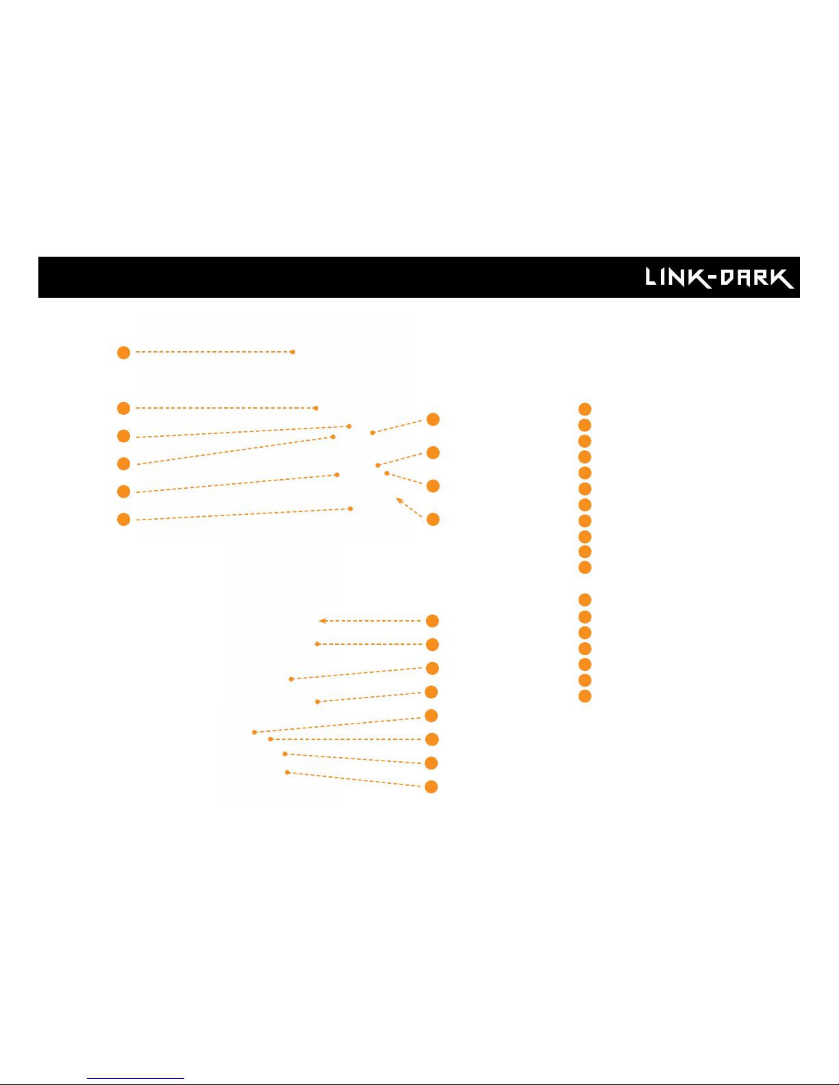
Antenna
LEDs
Photo lens
Day and night sensor
Viewing screen
Detection lens
Test light
Navigation buttons
ON / OFF Switch
SD card inserts
Battery compartment &
Micro SIM card inserts
Strap installation grooves
Locking latch
Cable lock holes
12V jack
Microphone
Tripod mount
Battery door push button
1
2
3
4
5
6
7
8
9
10
12
13
15
16
11
17
18
14
5
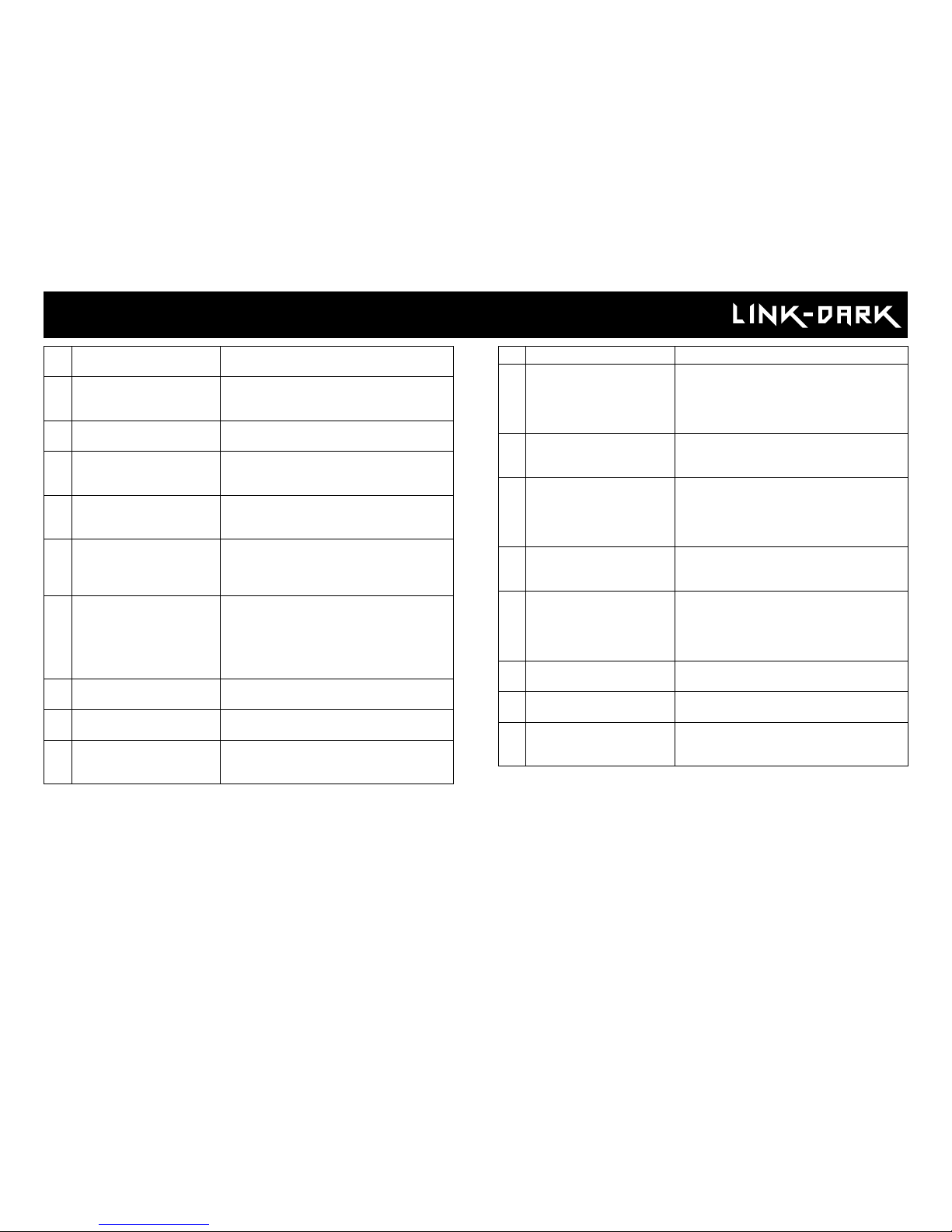
1 Antenna Allows cellular wireless communication.
2 LEDs Night lighting to obtain black and white
photos and videos. 42 invisible LEDs
3 Photo lens Image sensor and infrared lter.
4 Light sensor Detects the lighting conditions: color by
day and infrared by night.
5 Viewing screen Allows you to access the main menu and
view photos/videos.
6 Fresnel lens Expands the detection zone and inc-
reases the sensitivity of the camera’s
motion sensor.
7 Test light Flashes in TEST mode when there is
detection and ashes 30 seconds before
entering in PHOTO/VIDEO mode to notify
you to leave without being photographed
or recorded.
8 Navigation buttons Buttons to set the camera.
9 On-Off Switch Allows the user to turn on/off the camera.
10 MEMORY/SD card inserts An MEMORY/SD card is required to
record photos/videos.
11 Battery compartment AA batteries / Lithium pack compartment
Micro SIM card inserts A micro SIM card is required for cellular
functions. (included) The camera will not
work with a different SIM card then the
one provided by Spypoint.
12 Strap installation grooves Allows you to install the camera using
the installation strap included.
13 Locking latch Gives acces to the camera front control
pannel. Once locked it seals the camera
to protect it from weather and external
elements.
14 Cable lock hole Allows you to install a CL-6FT cable lock,
sold separately.
15 12V power jack This camera can be powered from an
external 12-volt DC input such as a
12V battery or a 12V adapter, each sold
separately.
16 Microphone Records sound in video mode.
17 Tripod mount Standard ¼-20" tripod mount.
18 Battery door push button Allows you to access the battery compart-
ment.
Components
6
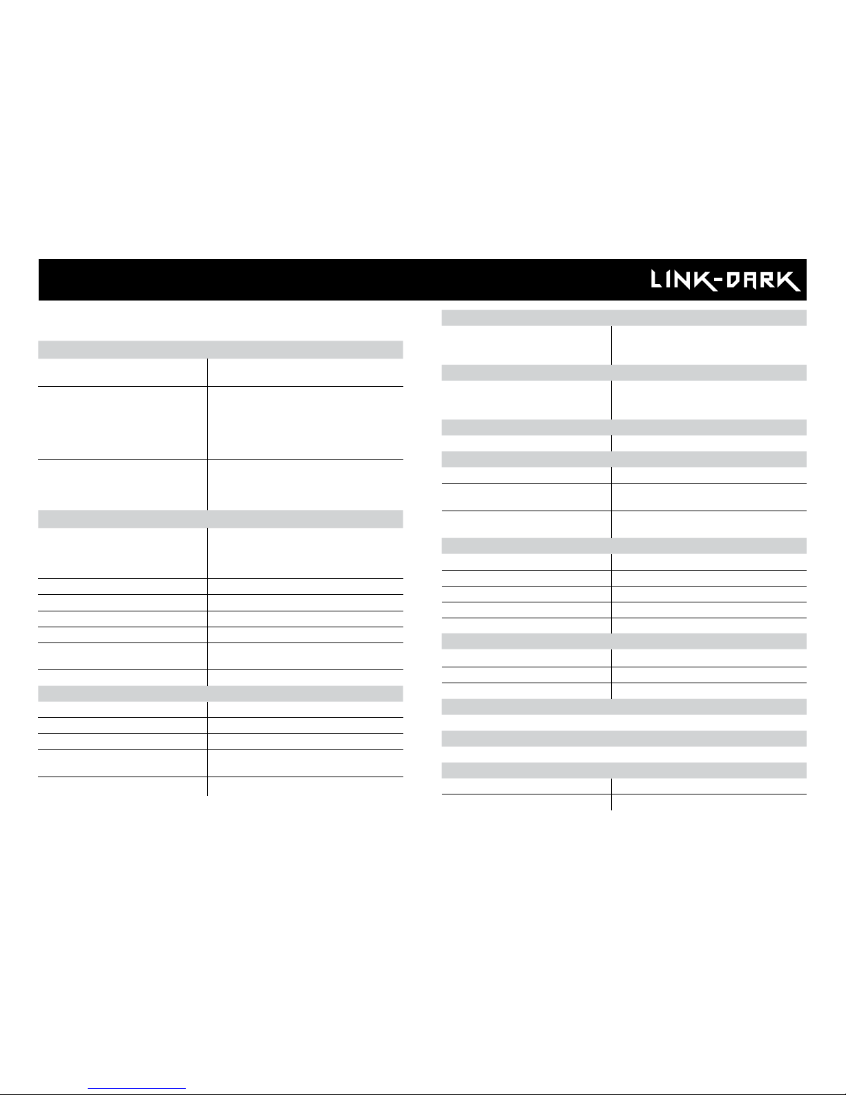
Specications
Cellular transmission
Frequency LINK-DARK: 4G LTE
LINK-DARK-V: 4G LTE (Verizon network)
Photo transmission Wireless photo transmission via the free,
SPYPOINT LINK App with a SPYPOINT
plan. For more information, visit the link
below.
WWW.SPYPOINT.COM/PLANS
Conguration Congurable from the settings menu
of the camera. Also remotely con-
gurable via the free SPYPOINT LINK
app.
Photo recording
Photo resolution cell OFF mode High: 12 MP
cell OFF mode Normal: 2 MP
cell ON mode High: 10 MP
cell ON mode Normal: 2 MP
Software 48 MP 48 MP
File format JPG
Time lapse mode Intervals from 3 min to 24h
Multi-shot mode Up to 3 photos per detection
Stamp Date, time, temperature (°C/°F) and
moon phase
Capture mode Color by day, infrared by night
Video recording
Video resolution 1920 x 1080 (HD 1080p)
File format AVI
Sequence lenght Adjustable from 10s/30s/60s/90s
Stamp Date, time, temperature (°C/°F) and
moon phase
Capture mode Color by day, infrared by night
Audio
Sound recording
(automatically recorded in video
mode)
Mono
Memory storage
Capacity •Internal memory: none
•External memory : standard full size
SD/SDHC (up to 32 GB) (Not include)
Viewing
Built-in screen ACL 2.0’’
Optional power sources
Alkaline or lithium batteries 8 x AA
Lithium battery pack Rechargeable battery pack
(LIT-09/LIT-C-8)
External (12V jack) 12V battery (KIT6V-12V, KIT-12V,
BATT-12V) or 12V adapter (AD-12V)
Detection system
Motion sensor PIR
Detection angle 45°
Detection distance Up to 90' ft.
Trigger speed 0.07 sec
Delay between each detection Adjustable from Instant to 30 min
Night time illumination system
LEDs 42 LEDs
Flash range Up to 100 ft
Exposure Automatic infrared level adjustment
Optical eld of view
40°
Dimensions
3.8” W X 6.9” H X 3.9” D
Recommendations
Operating temperature (-30 °C to + 50 °C) (-22 °F to +122 °F)
Storage temperature (-40 °C to + 60 °C) (-40 °F to +140 °F)
LINK-DARK & LINK-DARK-V

7
POWER SOURCES
AA BATTERIES
This camera can be powered by 8 AA batteries
(1.5V). The use of alkaline or lithium batteries is
recommended.
To ensure maximum performance of the camera
and prevent battery leaks, we recommend the
use of new batteries. Make sure to insert each battery
with the correct polarity. (Negative or at end against
the metal spring plate) Do not mix battery type - use
ALL alkaline or ALL lithium. Do not mix old and
new batteries. Rechargeable AA batteries are not
recommended as the lower voltage provided can
cause operational issues.
LITHIUM BATTERY PACK
This camera can be powered by a rechargeable
lithium battery pack LIT-09/LIT-C-8 (sold separately). This type of battery is less affected by cold
temperatures and lasts up to 2 times longer than
alkaline batteries.
Power
RECHARGEABLE 7.4 VOLT LI-ION POLYMER BATTERY 2.0 Ah
RECYCLE OR DISPOSE OF PROPERLY
Li-ion
Made in China
|
Fabriqué en Chine v2.3
www.spypoint.com
P INTSPY INTPSPY
Models: LIT-09: Battery only
LIT-C-8: LIT-09 Battery & charger
WARNING: To reduce risk of fire or burns,
- Do not attempt to open, disassemble, or service the battery pack.
- Do not crush, puncture, short external contacts, or dispose
of in fire or water.
ATTENTION: Pour réduire les risques de feu ou de brûlures,
- Ne pas essayer d’ouvrir, désassembler, ou de réparer la pile.
- Ne pas frapper, percer, court-circuiter les contacts externes
de la pile ou mettre dans le feu ni l’eau.
EXTERNAL (12V)
This camera can also be powered by an
external 12-volt DC input such as a 12-volt
battery (KIT-12V, BATT-12V or KIT6V/12V) or a 12volt adapter (AD-12V), sold separately. It is impossible to use a solar panel directly plugged in the
12v. jack. The camera is not built to take charge
of that kind of power supply. The use of a solar
panel directly in the camera will not recharge or
keep charge of any AAs or the lithium pack, at all.
In order to use a solar panel, this one needs to be
combined with the use of a 12v. battery as it needs
to be plugged in the 12v.
DC 12V

8
MEMORY/SD CARD
A memory card is required to record photos and videos. The camera is
compatible with SD/SDHC memory cards, up to 32 GB capacity (sold
separately). The use of a MICRO SD card IS NOT recommended.
The screen displays "Insert Memory Card" when the camera is turned on
and no memory card is used.
Here is a table of the approximate number of pictures and video length that
can be recorded on different memory card capacities. Refer to those corresponding to the camera model accordingly.
Note: This SPYPOINT camera is equipped with continuous le recording.
When the memory card capacity is full, the camera will continue to record
photos or videos by deleting the rst recorded les.
4 GB 8 GB 16 GB 32GB
Photo
12 MP 1600 3200 6300 12600
Video
1280 x 720 40 min 1h20 2h40 5h20
Memory/SD card & ''Busy'' light
INSERTING THE MEMORY CARD
Before inserting or removing a memory card, always turn off the camera to
prevent loss or damage. Also make sure the switch on the side of the card
SD card is set on unlock.
Insert a standard full-size SD/SDHC memory card (up to 32 GB capacity) in
the SD card inserts, label side facing upward. The card is inserted correctly
when a click is heard.
We strongly suggest to slow format the SD card on a computer before
use, even more if it has been used in another device. This will maximize
the memory card capacity and compatibility.
REMOVING THE MEMORY/SD CARD
Lightly push the memory card into the camera once to pop it out and remove it.
BUSY LED
The BUSY light is located at the back of the camera , on the battery door itself.
It is a diagnostic tool. It lights up when the camera starts, when the camera
records a le and in TEST mode in same time as the test light (located in
front of the camera). Once the camera gets to the end of the connection
process, the BUSY light will light ON, solid, as the camera is recording a picture/video then go OFF and will light ON again as sending the information
in your account.

9
Use the and buttons to navigate in the interface and modify the selection, the OK button to select and the button to return to the previous
menu.
START CAMERA
Allows you to start the camera in either, PHOTO, VIDEO or TIME
LAPSE mode. When a mode is selected, the test light in front of the
camera will ash for 30 seconds and a countdown will appear on the
screen to allow you to leave the area without being photographed.
DETECTION TEST
Allows to test the detection system of the camera. When the
DETECTION TEST mode is selected, no photo or video is recorded. Walk
perpendicularly in front of the camera. When the camera detects a
movement, the busy light blinks to indicate that normally, a photo
or video would have been recorded. If the system does not detect
the movement, increase the detection distance using the
"Sensitivity" option in the settings menu and revise the camera installation.
VIEW
Allows you to view or delete recorded photos and videos on the camera screen.
9/9
1
2
3
1
Selected photo / total number of photos
2
The play icon indicates that this element is a video
3
The outline indicates which photo is selected
Viewing on the camera screen:
When the VIEW mode is selected, the latest photos or videos recorded
appears as thumbnails gallery on the screen. Press or to navigate
this page, and press OK to view an enlarged picture. To view the next or
previous one press or . Press back to return to the thumbnail view.
When a large photo is open, press OK to view the different options available:
Play: Allows you to play or pause the video on the screen (this
option is available only for videos).
Zoom: Allows you to zoom in or out.
Date and time: Allows the user to view the date and time printed on
the photo.
Protect: Allows you to protect a photo or video to prevent it from
being deleted by selecting "Erase All".
Erase: Allows to erase the photo or the video appearing on the
screen from the memory card.
Erase all: Allows you to erase from the memory card all stored
photos and videos, with the exception of protected les.
Format: Allows to format the memory card and delete all protec-
ted photos and videos.
Exit: Allows to exit the menu and return to the viewing screen.
SETTINGS
Allows you to congure the different settings on the camera. From
PHOTO, VIDEO, TIME LAPSE, WIRELESS or GENERAL settings.
Main Menu

10
Settings
PHOTO SETTINGS
Sets the options of the PHOTO mode.
Delay:
(Instant/10s/1m/3m/5m/10m/15m/30m)
Allows you to choose the time interval between each detection before the
camera records the next photo. A longer delay minimizes the number of
photos taken and maximizes the battery life. A shorter delay maximizes
the number of photos taken but requires more battery power. A shorter delay interval is recommended when the camera is used for security
purposes.
Multi-shot:
(1/2/3 consecutive shots)
Takes up to 3 consecutive shots at each detection, with a 5-second
delay between each photo. This option allows the user to get up to 3
photos when the camera is set in PHOTO mode.
TIME LAPSE SETTINGS
Sets the options of the TIME LAPSE mode.
Interval:
(From 3m to 24h)
Allows the camera to take photos at regular preset intervals. For example,
if "5m" is selected in the TIME LAPSE mode, the camera takes a photo
every 5 minutes. This option will disable the detection.
Note: The TIME LAPSE mode only applies for photos, not videos. When
the TIME LAPSE mode is selected, the DELAY option and the MULTISHOT mode are disabled.
VIDEO SETTINGS
Sets the options of the VIDEO mode.
Delay:
(Instant/10s/1m/3m/5m/10m/15m/30m)
Allows the user to choose the time interval between each detection before
the camera records the next video. A longer delay minimizes the number
of videos taken and maximizes the battery life. A shorter delay maximizes
the number of videos taken but requires more battery power. A shorter delay interval is recommended when the camera is used for security
purposes.
Video length:
(10s/30s/60s/90s)
Allows the user to select the duration of the recording when the camera
is set in VIDEO mode.
Recommended settings
The camera can be congured for in trail usage.. This situation usually
presents low activity levels, fast subjects and a small number of photos is
expected. These settings increase the chances of capturing animals that
follow each other.
The camera can also be congured for feeder's site usage.. This situa-
tion usually presents high activity level, slow subjects and a large number
of photos is expected. These settings moderate the number of photos
taken while capturing overall activity on the feeder's site.
Here is a table showing the suggested settings for each situation:
Trail Feeder
Delay Instant 5 min
Multi-shots 1 2-3
When these recommended settings are not adapted to the situation,
battery life can be affected.
Photo rst:
(On/Off)
When this option is enabled, a photo is taken immediately before each
video.
Note: The le name of the photo corresponds to the digit before the video le name. For example, if the name of the photo is PICT001.JPG, the
name of the video will be VID001.AVI. The video mode will record videos
on the SD card but will not transfer them to your account. The Photo
rst option will send you the picture taken just before the video starts.
In order to view those videos, you need to retrieve the SD card from the
camera and read it from a computer.

11
GENERAL SETTINGS
Sets the general options of the camera.
Language:
(English/Français/Deutsch)
Allows to select a language for the camera menus.
Date format:
(MM/DD/YY, DD/MM/YY)
Allows to set the date as Month/Day/Year or as Day/Month/Year.
Time format:
(12H/24H)
Allows to set to standard time or military time.
Date:
Allows to set the date
Time:
Allows to set the time
Sensitivity:
(Low/Medium/High)
Allows to choose the sensitivity of the motion sensor.
The camera will only detect sources of heat in motion. Make sure to have
the least possible objects in front of the camera during the positioning. This
prevents the camera from taking photos when oriented towards the sun
while an object is moving in front of the camera. (e.g. a branch, foliage,
reection of the sun on water or snow.)
Settings
WIRELESS SETTINGS
Sets the wireless options of the camera.
Cellular:
(On/Off)
Allows to turn ON or OFF the transmission of pictures
Frequency:
Allows you to choose the number of transfers that the camera performs in a
day, to send the pictures in the account. Note that the transfer frequency
period is divided on a 24h period. It is important to note that this operation is battery consuming. Increasing the frequency will use more battery
power.
First Transfer time:
Allows to choose at what time of the day the camera
communicates for the rst time. It is setting your camera to communicate
once a day with your account, even if there are no pictures, so you will get
the status and see that the camera is still working. ) It also sets the rst
time frame for the transmission frequency.
GPS:
(On/Off)
Allows the camera to send GPS coordinates while it communicates accordingly with the chosen settings and plan.

12
Night mode:
Allows to set the best option for night mode photos.
Temp. units:
(°C/°F)
Allows to select the temperature display.
About the device:
Allows the user to display system information:
- Software version number
- Hardware version number
- Model
- SIM card number
& more.
Factory reset:
Allows to reset the device congurations to its original state.
Quality:
(Normal/High)
Allow to set the photo quality. (2MP/12MP)
Schedule
Allows you to set the working period of the camera for each day of the
week. The start and stop time are the hours during which the camera is
in action and can record pictures or videos. For a continuous 24/7 operation, Start and stop time should be the same, such as 00:00 or 12 am
/12 am.
Note: The hours can be recorded over a 12 or 24-hour period. Refer to
the «Time format» option.
Battery type:
(AA/LIT-09/12V)
Allows the user to select the battery type in use to get a more precise
battery level reading
Info on photos:
(Yes/No)
Allows to have date, time, temperature and moon phases on the photos.
New moon
Waxing Crescent
First Quarter
Waxing Gibbous
Full moon
Waning Gibbous
Last Quarter
Waning crescent
illumination modes comparison* (Night modes)
* Available for photos only
optimal
MODE
IR-boost
MODE
blur reduction
MODE
Blur reduction
Battery life
Flash range
Settings

13
6
1
2
3
4
Menu: Read messages, set the notications, language, login.
Camera name: Select the camera you want to view or setup.
Current tab: Indicate in what tab section you currently are.
Plan: Current plan.
Photos: Photo gallery sorted by date & time.
Tab selection: Select the tab section you want to consult.
1
3
5
2
4
LEVELS
Consult camera signal strengh, battery level, SD card used space & more.
GENERAL INFORMATION
Gives information on the model, version, last communication, amount of
pictures transfered this month, temperature and battery type readings.
SETTINGS
Modify the camera settings, sychronization frequency & others.
BASIC Mode - PHOTO
Set Delay, Multi-shot, Sensitivity & Camera name.
Mode - TIME LAPSE
Set Interval and camera name.
Mode - VIDEO
Set Delay, Sensitivity, Photo rst & Video length.
CELLULAR SETUP
Set Cellular transmission, First transfer time & frequency, Take a photo at next
transfer.
ADVANCED OPTIONS
Set the Date format, Temp. unit., Night mode and Schedule.
OTHER OPTIONS
Report camera stolen,Disable BUCK TRACKER.
WIRELESS SETUP OF THE LINK CAMERA
• Note that any modicaction of the settings through the app will carry
over to the camera at the end of the next synchronization.
• Settings in the App are the same one as in the camera.
• Once in the app, if you don't recall what function a setting is for, you can
fast touch the setting and an information tag will appear.
PHOTOS
Photo gallery, sorted by date, months and years. It also lets you
share, download ans erase your pictures.
• Scroll up or down to view your photos by date.
• Touch tap on a photo to select it and enlarge it.
□ Swipe left to see previous one or right for the next one.
□ Click on the arrow top right of the screen to share the photo.
□ Keep your nger on a photo to be able to delete it from the App.
□ Swipe up or down to return to the PHOTOS tab & refresh the screen.
ACCOUNT
Select and subscribe to a Data plan, modify your prole information.
DATA PLAN
4 Plans are available: ''Annual'' and ''Annual+'' running for 12 months each,
and ''Hunting'' plan for 3 months. If you choose not to activate a plan, note
that you’ll still be able to receive picures, under the FREE plan. Allowing you
to receive up to 100 photos /month with a photo history of the last 7 days.
MODIFY YOUR PROFILE INFORMATION
Modify your prole, Name, Address, Phone number & more.
STATUS
Show camera's information, transferred in the last communication.
SPYPOINT LINK app
Login in the SPYPOINT LINK app, gets you directly on the Photos tab. From
there, you'll see the latest photos received, sorted by date & time.
6
5

14
Installation & Mounting bracket
INSTALLATION
Recommended installation height:
Camera should be installed to aim the animal’s mid-body.
Ideal installation for quality pictures & videos:
For a better eld of view, the targeted animal should be ranged at a 25 feet
/ 7.5m distance away from the camera.
To get brighter pictures at night, it is important to consider having back
-
ground elements to reect the camera's infrared. (e.g. Trees or fence)
Make sure the front of the camera is free of any obstructions.
The installation area should be cleared from branches or bushes.
These could be responsible for triggering false detections when combined
with heat, reections and/or wind. Setting the sensitivity level of the
camera too high can also result in false detections.
DETECTION/TRIGGER ZONE
In order to get the best detection zone coverage, you need to consider that
the trig
ger zone is what will be displayed in the middle of a picture. The
detection works on a at level and will give better results if you consider
side to side motion.
Here is an exemple of a proper installation.
Every motion within the red rectangle will trigger the camera. Everything
under or upper those limits will not. By looking at your photos you can see
if the camera is aiming properly at the action path.
MOUNTING BRACKET
To remove the camera from the mounting bracket:
1. Push the tab to release the camera from the mounting bracket.
2. Remove the camera.
INSTALLATION WITH THE SUPPLIED STRAP
Use the mounting bracket or the camera strap installation grooves to x the
camera. The dimensions of the strap (included) is 1" X 60".

15
To transfer photos/videos to a computer:
• Turn OFF the camera.
• Remove the SD card from the camera.
• Insert the SD card into the computer reader, or use a memory card
adaptor.
• The computer will detect the card and install the driver automatically.
For a PC
Click on "My Computer" or «This PC» on your Desktop
Locate your device under "Removable Disk" and then click to access it.
Then click on "DCIM" and "100DSCIM" to nd all recorded photos and
videos.
Select the photos you want to copy. The easiest way is to select them all by
clicking on the Home tab and the Select all on the right-hand side. (You can
also press Ctrl and the ‘A’ key, or click the Edit menu and choose select all
in other versions of Windows)
Click the Copy icon on the left-hand side of the ribbon (or hold Ctrl and press
C). [NOTE: If you don't want to select all photos, hold down the Ctrl key
and click on the photos you do want to select before clicking the Copy icon]
Navigate to the folder in which you would like to store your images, or
create a new folder by clicking the New Folder button in the ribbon. (You
can also press Ctrl–Shift–N together to create a new folder, or right-click
in some empty space in the Pictures folder and choose New, then from the
next menu: Folder)
Type a name for your new folder, press Enter and then double-click on the
folder to open it.
From the Home tab, choose Paste (or hold Ctrl and press V). The photos will
be copied into the new folder.
File transfer to a computer
For a Mac
Click the Finder icon in the Dock.
Locate your device under the Devices tab and then click to access it.
Then click on "DCIM" and "100DSCIM" to nd all recorded photos and
videos.
Click Edit on the toolbar running along the top of the screen and then press
Select All to highlight every single image on the device. Select All is also
achievable by pressing the ⌘ and A key simultaneously on your keyboard.
Alternatively, if you do not wish to import all, you can individually highlight
the images you would like to transfer by holding ⌘ and clicking the le-
name.
Click Edit once again and then Copy (or ⌘ and C) to copy the highlighted
images.
Navigate to the folder in which you would like to store your images, or
create a new folder by right-clicking and pressing CTRL simultaneously, then
select New Folder from the menu.
Click Edit and then Paste (or ⌘ and V) to copy your chosen images from
your device to the selected folder.
Images may take several minutes to transfer depending on the le size and
the amount of images you are importing.
Once your images have transferred, click the Eject icon situated alongside
the name of your device and then unplug the device from your Mac.

16
Available accessories
12-volt Adaptor
#AD-12V, AC adaptor (6V to 12V).
Powers the camera from an electrical outlet.
Long range cellular antenna
#CA-01, External omnidirectional
antenna to amplify the cellular
signal. Cable length of 16 ft with
male RP-SMA connector.
12V DC Power cable
#CB-12FT, 12 ft power cable with
alligator clips at one end to connect
a 12V battery to a camera.
Rechargeable 12V battery,
charger & housing kit
#KIT-12V, 12-volt 7.0Ah rechargeable battery with a water
resistant ABS plastic case, AC
charger, 12 ft power cable
Lithium battery pack & charger
#LIT-C-8, Rechargeable lithium
battery pack and AC charger with
charge indicator light. Fits all SPYPOINT cameras.
Memory Card
Carte Mémoire
ULTRA HIGH SPEED/ULTRA HAUTE VITESSE
/
R
F
N
16 GB
SD Memory card 16GB
#SD-16GB, SDHC UHS-1 memory
card 16 GB, ultra high speed Class
10.
Solar panel
#SP-12V, Maintains the charge of
the lithium battery pack directly
into the compatible cameras. Can
be combined with any 12V battery.
Cable lock
#CL-6FT, 6 ft cable lock ts all
SPYPOINT cameras.
Camera mount
#MA-360, Adjustable mounting
arm, ts all cameras that have a
standard ¼-20" tripod mount. It
can rotate 360° and tilt approx +/90°. Also available in black.
Steel security box
#SB-200, Steel box to secure the
camera against theft. It also protects
it from breakage caused by bears or
other animals. Fits all SOLAR 42 LED
SPYPOINT cameras.
Steel security boxes may reduce the
wireless functionalities of the product.
To obtain more information on other available accessories, we invite you on our web site at:
www.spypoint.com

17
Issue Possible solutions
Impossible to turn
on the camera
• Verify if there are batteries in the camera.
• Verify if the batteries are correctly installed.
• Replace batteries or recharge the lithium battery
pack.
The screen of the
camera turns off
• The camera may be set to PHOTO or VIDEO mode
and the screen turns off after a period of 30 seconds
in order to preserve battery life.
• The camera automatically resets itself to PHOTO or
VIDEO mode (along with the latest mode used
or selected) after 2 minutes of inactivity on the main
menu.
• To get the screen back, turn off the camera and turn
it on again.
The camera does
not respond
• Remove the batteries and reinstall them.
• Replace batteries or recharge the lithium battery
pack.
Impossible to take
photos/videos
• Verify if there are batteries in the camera.
• Replace batteries or recharge the lithium battery
pack.
• Verify if the camera is turned on.
• Slow format the memory/SD card in a computer.
• Make sure the camera detects movement by
proceeding to a Detection Test.
Red light in front
of the camera
blinks
• Camera is set on TEST mode.
• Camera is set on PHOTO or VIDEO mode. The red
light in front of the camera ashes for 30 seconds to
allow the user to leave without being photographed
or recorded.
Camera takes
black
photos / videos
• Verify the battery level to see if battery power is full
as the ash will stop operating near the end of the
battery life especialy if you're doing a video.
• Verify that there's something within the ash range
to reect the infrared back to the camera.
• If you're unsure if the ash is working properly, test
the camera in a dark room to see if you're able to have
black & white pictures or videos.
Photos / videos
appear dark at
night
• For best results, make sure the subject is within the
ideal ash range. Subjects may appear too dark at
greater distances.
Photos are blurry
• Low lighting conditions and fast moving subjects,
may produce streaks on the photo, try setting the
"Night mode" to "BLUR" to reduce the motion blur.
No person/animal
on photos
• Sunrise or sunset can trigger the sensor. Camera
must be re-orientated.
• At night, the motion detector may detect beyond the
range of the IR illumination. Reduce sensitivity
setting.
• Small animals may trigger the unit. Reduce
sensitivity setting and/or raise height of camera.
• Motion detector may detect animals through foliage.
• If a person or animal moves quickly, it may move out
of the camera’s eld of view before the photo is
taken. Move the camera further back or redirect the
camera.
• Make sure the mounting post or tree is stable and
does not move.
Troubleshooting

18
Error: SIM card
The SIM card is defective.
• Turn off the camera and turn it on again.
• Turn off the camera, then remove the SIM card and
insert it again as shown on the camera. The card is
inserted correctly when a click is heard.
Error: SIM locked
Your SIM card is locked.
• Contact the SPYPOINT customer service.
Error: SIM locked
(PUK)
Your SIM card is locked and requires a PUK.
• Contact the SPYPOINT customer service.
Error: SIM card
not supported
• The camera must use the SPYPOINT SIM card
provided with the camera.
Error: No service
The SIM card does not detect any signal.
• Get outside or near a window and restart the
camera a few times if required to get all the
information from the cell network.
* If the signal is still too low, there is a possibility to
get a Long range cellular antenna (CA-01), from our
website.
Error: Modem
There has been a communication problem between the
camera and the modem.
• Turn off the camera and turn it on again.
Error message Possible solutions
Insert memory
card
The use of a memory/SD card is required to record
photos and videos. Make sure to use a SDHC standard
full size 32 GBs and less memory card. DO NOT use a
MICO SD in an adaptor.
Card error
The camera cannot access the memory card.
• Turn off the camera and turn it on again.
• Turn off the camera, then remove the SD card and
insert it again. The card is inserted correctly when a
click is heard.
• Verify if the gold contacts are clean.
• Format the memory card. Slow format the memory/SD
card in a computer.
Low battery
Appears on the screen just before the camera turns
off. Replace batteries or recharge the lithium battery
pack. Always verify the battery level before using the
camera.
No image
The camera does not display any pictures/videos.
• Verify if the SD card is not locked.
• Verify if the memory card contains photos/videos
with a computer. Make sure to use a standard full size
32GBs and less SD card. Do not unse a MICRO SD
card in an adaptor.
Protected le
The le you want to delete is protected.
• Unprotect the photo in the View mode, then you will
be able to delete this le.
• Format the memory card to delete the les.
Error: No SIM
card
The SIM card is missing or defective.
• Turn off the camera and turn it on again.
• Turn off the camera, retrieve the SIM card and insert
it again as shown on the drawing in the battery case.
The card inserted correctly when a click is heard.
Troubleshooting

19
Warranty & Repair
This SPYPOINT product designed by GG Telecom, is covered by a two (2)
year limited warranty on material and workmanship starting from the
original date of purchase. The electronic sales receipt is the client’s proof
of purchase and must be presented if warranty service is needed. This
warranty will be honored in the country of purchase only.
This GG Telecom warranty does not apply to: (a) consumable parts,
including but not limited to batteries, which performance is designed to
decrease over the course of time; (b) damage caused by misuse, combined with another product, neglect, accidents, liquid contact, re, earthquake or any other external cause; (c) GG Telecom products that have been
purchased online from an unauthorized dealer; (d) products that have had any
modication or tampering; (e) cosmetic damage including but not limited
to scratches and broken plastic; (f) damage caused by operating the GG
Telecom product outside of GG Telecom’s recommendations.
INSTRUCTIONS FOR REPAIR SERVICE
GG Telecom will repair the product or replace it at its discretion with an
equivalent product without charge if covered by the warranty described
previously. The shipping fees for an item sent will be assumed by the
customer. GG Telecom will then pay for the return of the product covered
by the warranty.
For a product not covered by the warranty, the repair will be subject to a
reasonable charge and the customer will also assume all shipping costs.
IMPORTANT: Under no circumstances will GG Telecom accept returned
products without a RMA number. (Return Material Authorization) It is
essential to contact GG Telecom before proceeding to a return.
1. Before sending a product for repairs, please contact GG Telecom
technical support team by phone at : 1-888-779-7646, by email at
support@spypoint.com, via LIVE CHAT from the app itself or on our
website at www.spypoint.com,as most issues can be solved over
the phone or by email.
2. If a product needs to be sent, a RMA number will be given to authorize
the return of the product and for future reference.
3. The original receipt or a copy must be sent along with the package.
4. The RMA number must be written on the outside of the package and
sent to:
CANADA UNITED STATE
GG Telecom GG Telecom
120 J.Aurèle-Roux 1825 E Army Post Rd,
Victoriaville, QC Des Moines, IA 50320
G6T 0N5
The customer is liable for loss or damage to the product that may occur
during the shipping to GG Telecom. We recommend the use of a traceable
method of shipping to ensure protection.
WWW.SPYPOINT.COM
Sit back, relax & know you’re covered

20
FCC REGULATIONS
FCC Part l5
This equipment has been tested and found to comply with the limits
for a Class B digital device, pursuant to Part 15 of the Federal
Communications Commission (FCC) rules. These limits are designed to
provide reasonable protection against harmful interference in a residential
installation. This equipment generates, uses and can radiate radio frequency energy and, if not installed and used in accordance with the instructions,
may cause harmful interference to radio communications. However, there
is no guarantee that interference will not occur in a particular installation.
If this equipment does cause harmful interference to radio or television
reception, which can be determined by turning the equipment off and on,
the user is encouraged to try to correct the interference by one or more of
the following measures:
• Reorient or relocate the receiving antenna.
• Increase the separation between the equipment and receiver.
• Connect the equipment into an outlet on a circuit different from
that to which the receiver is connected.
• Consult the dealer or an experienced radio/TV technician for help.
Changes or modications to this equipment not expressly approved by the
party responsible for compliance could void the user’s authority to operate
the equipment.This device complies with Part 15 of the FCC rules. Operation
is subject to the following two conditions: (1) this device may not cause
harmful interference, and (2) this device must accept any interference
received, including interference that may cause undesired operation.
Regulations
 Loading...