

v1.0
USER MANUAL
Models:
IRON-9
IRON-10
C9
B10
G8
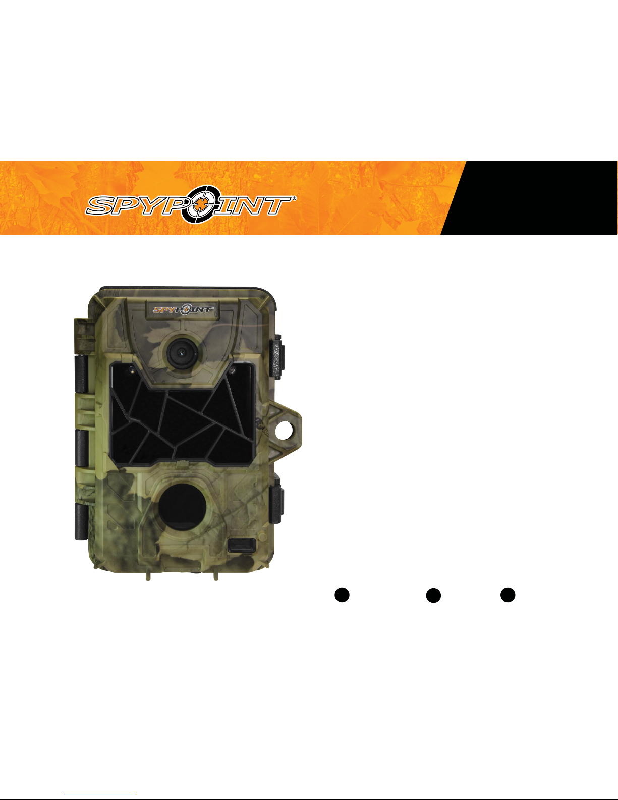
INVISIBLE LEDS TRAIL CAMERA
P INTSPY INTPSPY
IRON
1-888-779-7646support.spypoint.com
tech@spypoint.com
P INTSPY INTPSPY
THANK YOU FOR CHOOSING A SPYPOINT PRODUCT.
This manual will guide you through all the features of your device
so that you will get optimal use out of your SPYPOINT product.
Our priority is to provide outstanding customer service. If you need
support for your product, please contact the SPYPOINT technical
support or visit our website.
CONTACT
1-888-779-7646
tech@spypoint.com
www.spypoint.com
ABOUT US
GG Telecom’s mission is to offer products that are easy
to use, innovative, affordable and of exceptional quality.
Our SPYPOINT products are mainly used for hunting and
residential/commercial surveillance. They are distributed and
shipped all over the world and the market never stops growing.
Prosperous and respected, GG Telecom is a company that constantly
keeps abreast of new technologies and listens to its customers to
deliver cutting-edge products with practical solutions that improve
hunting and outdoor activities.
JOIN THE SPYPOINT COMMUNITY
NON-CELLULAR CAMERAS
Visit mySPYPOINT.com to create your free basic account.
facebook.com/SPYPOINT
twitter.com/SPYPOINTcamera
youtube.com/SPYPOINTtrailcam
CELLULAR CAMERAS
Visit mySPYPOINT.com to learn more about the
different accounts available.
For the latest version of the activation procedure, go to
support.spypoint.com/activation.
mySPYPOINT.com is an online camera & photo management system.
This incredible tool for hunters is available for all SPYPOINT cameras.

3
Package contents ......................................................................... 4
Components ................................................................................. 5
Power ........................................................................................... 7
Memory card ................................................................................ 8
BUSY LED ..................................................................................... 8
Settings ........................................................................................ 9
Distance ......................................................................................11
Sound recording ..........................................................................13
File transfer to a computer ..........................................................14
Troubleshooting ..........................................................................15
Error messages............................................................................15
Available accessories ...................................................................16
Specications
IRON-9 .........................................................................................18
IRON-10 .......................................................................................19
C9 ................................................................................................20
B10 ..............................................................................................21
G8 ................................................................................................22
Regulation ...................................................................................23
Limited warranty .........................................................................24
Repair service ..............................................................................24
Table of contents
IRON

4
USB
cable
Installation
strap
SPYPOINT
camera
Quick start
guide
Quick start guide
v1.3
Invisible LEDs
trail camera
Models:
IRON-9
IRON-10
C9 / B10 / G8
1-888-779-7646
support.spypoint.com
tech@spypoint.com
In the box
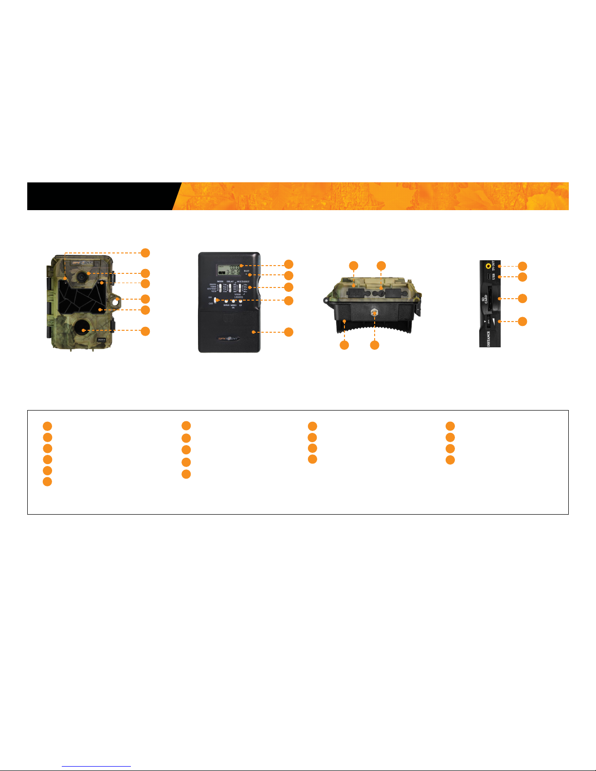
Components
Note: Memory card and batteries are sold separately.
Photo lens
Invisible LEDs
Test light
BUSY LED
Detection lens
Cable lock hole
Battery case
Congurationscreen
Switch panel
ON/OFF
Slot for installation strap
1
2
3
4
5
6
7
8
9
10
11
Tripod mount
Microphone
12V jack
USB port
TV OUT
Distance dial
SD card slot
12
13
14
15
16
17
3. INSTALL THE CAMERA WITH THE SUPPLIED STRAP
1. CHOOSE A POWER SOURCE
We recommend the use of new alkaline batteries to ensure
maximum performance of the camera. Rechargeable AA batte-
ries are not recommended.
2. INSERT THE MEMORY CARD
Insert an SD/SDHC memory card (up to 32 GB
capacity) in the card slot. The card is inserted
correctly when a click is heard.
Before inserting or removing a memory
card, always turn off the camera to
prevent loss or damage of the photos already
recorded.
Getting started
Useful: Detach the desired section of this guide and
insert it into the sleeve provided on the back housing of
the camera.
6 alkaline AA batteries
Lithium battery pack
LIT-09/LIT-C-8
18
Installation
strap
USB
cable
Quick start
guide
Camera
11
1
2
5
6
7
8
9
10
12
1314
16
15
17
18
3
4
Audio-video
cable
IRON
P INTSPY INTPSPY
Once installed, the inner part
of the camera can be removed
from the housing to easily
adjust the settings.
PRACTICAL TIP :
Recommended installation height:
about 3 feet above the ground.
Do not place the camera
facing the sun.
RECOMMENDATIONS:
3 ft
Audio-video
cable
Package contents
IRON
5
Photo lens
Invisibles LEDs
Test light
Light sensor
Fresnel lens
Cable lock hole
1
2
3
4
5
6
7
8
Conguration screen
BUSY LED
Switch panel
ON/OFF
Battery case
9
Slot for installation strap
Tripod mount
12V jack
Microphone
10
11
12
13
14
15
TV OUT
USB port
SD card slot
DISTANCE dial
16
17
18
19
1
2
3
4
5
6
9
8
7
10
11
12 13
14 15
16
17
18
19
Components
IRON

6
1 Photo lens Image sensor and infrared lter.
2 Invisible LEDs Night lighting to obtain black and white photos
and videos.
3 Test light Flashes in TEST mode when there is detec-
tion and ashes 60 seconds in PHOTO/VIDEO
mode to allow the user to leave without being
photographed or recorded.
4 Light sensor Allows the lighting of the LEDs panel at night.
5 Fresnel lens Expands the detection area and increases the
sensitivity of the camera’s motion sensor.
6 Cable lock hole Allows the user to install a CL-6FT cable lock,
sold separately.
7 Conguration screen To see battery level, date, number of recorded
les, error messages and settings options.
8 BUSY LED Lights up when TEST mode is activated.
9 Switch panel Buttons to set the camera.
10 ON/OFF Allows the user to turn on/off the camera.
11 Battery case Case for AA batteries or a rechargeable
lithium battery pack.
12 Slot for installation
strap
Allows the user to install the camera using
the installation strap included.
13 Tripod mount Standard ¼-20" tripod mount.
14 12V power jack This camera can be powered from an
external 12-volt DC input such as a 12V
battery or a 12V adapter, each sold
separately.
15 Microphone Records sound in video mode.
16 TV OUT Allows the user to view or delete photos/
videos directly on a TV.
17 USB port To transfer photos/videos to a computer.
18 SD card slot An SD card is required to record photos/
videos.
19 DISTANCE dial Allows the user to adjust the distance of
detection and the sensitivity of the detector.
Components
IRON

7
The battery level is shown on the LCD screen. When a single line remains,
the camera will continue to take photos but we strongly recommend
to change the AA batteries or charge the lithium battery pack before they
are empty (see gure below). If a video is being recorded and the battery
level reaches 0%, the camera saves the le before shutting down.
AA BATTERIES
This camera requires 6 AA batteries (1.5V). The use of alkaline or lithium
batteries is strongly recommended. Insert the batteries as indicated inside
the battery case. Battery polarity must be followed.
Please note that the voltage of rechargeable AA batteries (1.2V) is
insufcient to power the SPYPOINT camera. We also recommend the
use of new batteries to ensure maximum performance of the camera.
LITHIUM BATTERY PACK
This SPYPOINT camera can be powered by a rechargeable lithium battery
pack LIT-09/LIT-C-8 (sold separately). This type of battery is less affected
by cold temperatures and lasts up to 3 times longer than an alkaline
batteries.
EXTERNAL (12V)
This camera can also be powered by an external 12-volt DC input such as
a 12-volt battery (KIT-12V, BATT-12V or KIT6V/12V) or a 12-volt adapter
(AD-12V), sold separately. For the 12V available accessories, see p.16.
TIME BATTERY
The camera has a CR2032 lithium button battery which saves the time and
date. To replace the battery:
1. Turn off the camera and remove it from the housing.
2. Using a at screwdriver, push the tab to the right.
3. While pushing the tab, remove the compartment of the camera.
4. Replace the battery, the polarity must be respected (side + facing up).
6 alkaline AA batteries
Lithium battery pack
LIT-09/LIT-C-8
Power
IRON
8
MEMORY CARD
A memory card is required to record photos and videos. The camera is
compatible with SD/SDHC memory cards, up to 32 GB capacity (sold
separately).
When the camera is ON and no memory card is used, the screen displays
"CArd" meaning to insert one. When the SD card is full, the screen displays
"FUL".
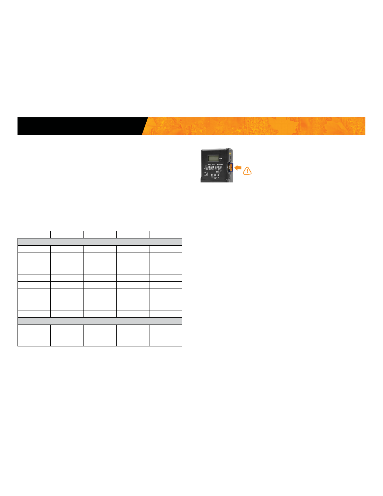
Here is a table of the approximate number of photos and length of videos
that can be recorded with different memory card capacities. Many photo and
video resolutions are noted, see those corresponding to the camera.
Note: This SPYPOINT camera is equiped with continuous le recording.
When the memory card is full, the camera will continue to record photos or
videos by deleting the rst recorded les.
4 GB 8 GB 16 GB 32GB
Photo
3 MP 4100 8200 16400 32800
4 MP 3800 7600 15200 30400
5 MP 3400 6800 13600 27300
6 MP 3200 6300 12600 25300
7 MP 2700 5500 10900 21800
8 MP 2400 4800 9500 19000
9 MP 2200 4500 8900 18000
10 MP 1900 3800 7600 15200
11 MP 1700 3400 6700 13400
12 MP 1600 3200 6300 12600
Video
320 x 240 4 h 8 h 16 h 32 h
640 x 480 2h10 4h10 8h20 16h40
1280 x 720 40 min 1h20 2h40 5h20
INSERTING THE MEMORY CARD
Insert an SD/SDHC memory card (up to 32 GB capacity)
in the card slot. The card is inserted correctly when a
click is heard.
Before inserting or removing a memory card, always
turn off the camera to prevent loss or damage of
the photos already recorded.
REMOVING THE MEMORY CARD
Lightly press the memory card into the camera once to pop it out of the slot
and remove it.
"BUSY" DEL
The "BUSY" light, located below the screen, It is a diagnostic tool. It lights
up when the camera starts, when the camera records a le and in TEST
mode at the same time as the test light (located in front of the camera).
Memory card/ "BUSY" LED
IRON

9
To congure the general settings, set the camera to SET/TEST mode. Press
OK to enter the menu. The ashing option is the one that can be modied
using UP/ DOWN. Press OK to conrm and to set the next option. Once you
went through all the options, turn the camera OFF to record the settings.
A: Set the Photo quality (High/Low) * see table on next page
B: Number of recorded les display
C: Set the Date/Time (MM/DD/YY, hh:mm)
D: Set the Temperature (Celcius/Farenheit)
E: Set the option Time-lapse (On/Off) *IRON-10 only
* This table shows the photo and video resolution depending on the
photo quality setting (High/Low).
1
MODE
PHOTO
Allows the user to take photos. When the PHOTO mode is selected, the test
light in front of the camera will ash for 60 seconds to allow the user to
leave the area without being photographed.
VIDEO
Allows the user to take videos. When the VIDEO mode is selected, the test
light in front of the camera (see above) will ash for 60 seconds to allow the
user to leave the area without being recorded.
SET-TEST
Allows the user to test the detection system of the camera. When the SET/
TEST mode is selected, no photo or video is recorded. Pass in front of the
camera from left to right. When the camera detects a motion, the test light
blinks to indicate that the camera would normally have saved a photo or
video. If the system does not detect the movement, increase the detection
distance using the DISTANCE wheel or realign the system differently.
1
2 3
4
A
D
B
C
E
Settings
IRON
IRON-9
(Non-HD videos)
IRON-10
(HD Videos)
Video
Low 320 x 240 640 x 480
High 640 x 480 1280 x 720
Photo
Low 3 mp
High 9 mp 10 mp

10
Here are the options available by pressing MENU/OK:
View Date/Time:
Allows the user to view the date and time printed on
the photo.
Protect:
Allows the user to protect a photo or video to prevent it
from being deleted by selecting "Erase All".
Erase one:
Allows the user to erase the photo or the video seen on
the screen from the memory card.
Erase all:
Allows the user to erase all stored photos and videos,
with the exception of protected photos and videos from
the memory card.
Format:
Allows the user to erase the entire contents of the
memory card, including the protected les.
Language: Allows the user to change the display language.
Exit:
Allows the user to exit the menu to return to the
viewing screen.
Here are the different moon phases that are printed on photos.
(IRON-10 / C9)
New moon:
Waxing Crescent:
First Quarter:
Waxing Gibbous:
Full moon:
Waning Gibbous:
Last Quarter:
Waning crescent:
INSTALLATION WITH THE SUPPLIED STRAP
The dimensions of the strap (included) is 1" X 60".
Recommended installation height: about 3 feet above the ground.
Do not place the camera facing the sun.
VIEW
Allows the user to view or delete recorded photos and videos directly on a
television.
1. Turn OFF the camera.
2. Set the switch MODE to VIEW.
3. Connect the yellow end of the audio-video cable (supplied) into the
VIDEO IN of the TV and the other end into the TV OUT of the camera.
4. Turn ON the camera and the last recorded photo or video will appear. To
change the photo or the video, use the UP or DOWN button.
Settings
IRON

11
2
DELAY (IN PHOTO MODE)
Allows the user to choose the time interval between each detection before
the camera records the next photo or video*.
Additional setting: It is possible to decrease the delay between detections
to 10 seconds (instead of 1 minute) by using the following procedure. Note
that the battery life will be affected.
1. Turn OFF the camera.
2. Press and hold the UP button, turn the camera on. "10_S" appears on
the screen meaning the 1 minute delay has been replaced by a 10 second
delay.
3. To reset the camera to 1 minute delay, follow the same procedure. "1_M"
appears on the screen (see gure below).
DELAY (WITH TIME LAPSE ON)
Allows the camera to take photos at regular preset intervals without detection (IRON-10). The user can obtain photos of game outside the detection
range of the camera.
To set the Time-lapse option:
1. Turn the Time-Lapse option ON in the settings menu of the camera.
2. Set the switch panel in PHOTO mode, and choose the intervals with the
DELAY switch.
3. To go back to regular photo settings, turn OFF the Time Lapse option.
Note: The TIME LAPSE mode only applies for photos, not videos.
3
MULTI-SHOT
Takes up to 4 consecutive shots at each detection, with a 10 second delay
between each photo. For the cameras with a Flash unit, the delay between
each photo will be 15 seconds. This option allows the user to get up 4 photos
from different angles when the camera is in PHOTO mode.
4
VIDEO LENGTH
Allows the user to select the duration of the recording when the camera is
set in VIDEO mode.
DISTANCE
Turn the DISTANCE dial to the right to increase the detection distance and
the sensitivity of the detector.
The camera is equipped with a detector sensitive to infrared. The system
will only detect a heat source in motion. The greater the mass of heat, the
more sensitive the system is. The range of detection is between 5 and 65
feet. The best way to adjust the distance is to set the camera to SET/TEST
mode. Make sure to have the least amount of objects possible in front of
the camera during positioning. This will prevent photos being taken by the
camera when oriented towards the sun at the same time an object moves in
front of the camera (e.g. a branch).
Settings
IRON
10_5
10 s delay 1 min delay

12
Here is a table of approximate detection distances and width of the
detection area according to the DISTANCE dial setting. The data can be
affected by the size of the subject and the outside temperature. Note that
this data is for illustrative purposes only.
Value on
dial
Sensitivity
Detection
distance
(ft)
Width of the
detection area (ft)
MIN.
Gradually
increases
5-30 3
2
4
30-50 15
6
8
50-65 30
MAX.
CAMERA
3
15
30
Settings
IRON

13
The SPYPOINT camera offers the possibility to record sound in VIDEO
mode. When the VIDEO mode is selected, the camera automatically re-
cords the sound. Under the camera, you will nd a rubber cap with the
inscription MIC. If the user does not want to record the sound, the rubber
cap needs to stay in place. If sound recording is required, the user must
lift the rubber cap and turn it slightly so that the microphone receiver is
completely cleared (See gure below).
Sound recording
IRON

14
To transfer photos/videos to a computer:
1. Turn OFF the camera.
2. Connect the USB cable (supplied) from the camera to a computer.
3. The computer will detect the camera and install the driver automatically.
4. Click on "My Computer" and select "Removable Disk".
5. Then click on "DCIM" and "100DSCIM" to nd all recorded photos and
videos.
6. Drag or save the les to the desired location.
Taking the memory card out (sold separately) of the camera and inserting it
into the computer slot will achieve the same results.
USB
File transfer to a computer
IRON

15
TROUBLESHOOTING
Problem Possible solutions
Impossible to
turn on the
camera
• Verify if there are batteries in the camera.
• Verify if the batteries are correctly installed.
• Verify if the battery switch position is positioned
according to the power source.
• Install the latest update (available on
www.spypoint.com under SUPPORT section).
• Replace alkaline batteries or recharge the lithium
battery pack.
The screen of the
camera turns off
• The camera may be set to PHOTO or VIDEO mode
and the screen turns off after a period of 60 seconds
in order to preserve battery life.
• To return to the screen, turn off the camera and turn
it on again.
The camera does
not respond
• Remove the batteries and reinstall them.
• Replace alkaline batteries or recharge the lithium
battery pack.
The camera
works, but is
losing its time
and date settings
• The time battery must be replaced.
Impossible to
take photos/
videos
• Verify if there are batteries in the camera.
• Replace alkaline batteries or recharge the lithium
battery pack.
• Memory card is full.
• Verify if the camera is turned on.
No person/animal
on photos
• Sunrise or sunset can trigger the sensor. Camera
must be re-orientated.
• At night, the motion detector may detect beyond the
range of the IR illumination. Reduce distance setting.
• Small animals may trigger the unit. Reduce distance
setting and/or raise height of camera.
• Motion detector may detect animals through foliage.
• If a person or animal moves quickly, it may move out
of the camera’s eld of view before the photo is
taken. Move the camera further back or redirect the
camera.
• Make sure the mounting post or tree is stable and
does not move.
Red light in front
of the camera
blinks
• MODE switch is in SET/TEST.
• MODE switch is in PHOTO or VIDEO. The red light in
front of the camera ashes for 60 seconds to allow
the user to leave without being photographed or
recorded.
The photos/
videos do not
appear on the
television
• Verify if the camera is correctly connected to the
television using the RCA cable.
• Verify if the memory card contains photos/videos.
The computer
does not
recognize the
camera
• Verify if the camera is properly connected to the
computer using the USB cable.
The computer
can’t play videos
• The .MP4 video format requires the use of a video
player software compatible such as VLC, Windows
Media Player or QuickTime.
ERROR MESSAGES
There is no memory card in the camera, insert a card.
The memory card is full, delete the les or use a new
memory card.
Troubleshooting / Error messages
IRON

16
To obtain more information on the available accessories, go to
www.spypoint.com. Here are the main accessories available:
POWER
12-volt Adaptor
#AD-12V, AC adaptor (6V to 12V).
Powers the camera from an electrical outlet.
Universal power kit
#KIT6V-12V, Universal kit with 6
volts or 12 volts output. Compatible with all SPYPOINT products or
any other products equipped with
a 6 volts or 12 volts power jack. 6
connectors included to t any device. Includes 6 volts (5.6Ah) and
12 volts (2.8Ah) output congura-
tion and AC charger.
12V DC Power cable
#CB-12FT, 12 ft power cable with
alligator clips at one end to connect
a 12V battery to a camera.
Spare power cable
#PW-12FT, Spare 12 ft power
cable, to connect the camera to
the KIT-12V.
Rechargeable 12V battery,
charger & housing kit
#KIT-12V, 12-volt 7.0Ah rechargeable battery with a water
resistant ABS plastic case, AC
charger, 12 ft power cable (#PW-
12FT) and carrying strap included.
Compatible with all SPYPOINT
products equipped with a 12V
power jack.
Rechargeable 12V battery &
charger set
#BATT-12V, 12-volt 7.0Ah rechargeable battery and AC charger to
power the camera.
Lithium battery pack
#LIT-09, Additional rechargeable
lithium battery pack. Fits all SPYPOINT cameras.
Lithium battery pack & charger
#LIT-C-8, Rechargeable lithium
battery pack and AC charger with
charge indicator light. Fits all SPYPOINT cameras.
MEMORY CARD
P INT
SPY
INTP
SPY
Memory Card
Carte Mémoire
HIGH SPEED/HAUTE VITESSE
/
R
F
N
SD Memory card 8GB
#SD-8GB, SDHC memory card
8 GB, High speed Class 6.
Available accessories
IRON
Memory Card
Carte Mémoire
ULTRA HIGH SPEED/ULTRA HAUTE VITESSE
/
R
F
N
16 GB
SD Memory card 16GB
#SD-16GB, SDHC UHS-1 memory
card 16 GB, ultra high speed Class
10.

17
INSTALLATION AND SECURITY
Steel security box
#SB-91, Steel box to secure
the camera against theft. It also
protects it from breakage caused
by bears or other animals. Fits all
35 and 46 LED SPYPOINT cameras. Also available in black.
Cable lock
#CL-6FT, 6 ft cable lock ts all
SPYPOINT cameras.
Camera mount
#MA-360, Adjustable mounting
arm, ts all cameras that have a
standard ¼-20" tripod mount. It
can rotate 360° and tilt approx +/90°. Also available in black.
Tripod
#TP-CAM, SPYPOINT Lightweight
tripod, in black aluminum, with a
unique anchor system and a removable quick release plate. Max.
height: 4.9 ft (1.5 m), min. height:
1.7 ft (0.5 m), max. load weight:
11 lbs (5 kg). Fits most SPYPOINT
products.
Available accessories
IRON

18
Photo recording
Photo resolution 3 MP, 9 MP
File format JPG
Multi-shot mode Up to 4 photos per detection
Stamp (only on photos) Date, time, and temperature (°C/°F)
Capture mode Color by day, black and white by night
Video recording
Video resolution 320 x 240 or 640 x 480
File format AVI
Sequence lenght Adjustable from 10 to 90 s
Capture mode Color by day, black and white by night
Audio
Sound recording
(automatically recorded in video
mode)
Mono
Memory storage
Support •Internal memory: none
•External memory : SD/SDHC card
(up to 32 GB)
Viewing
TV output Composite video (PAL/NTSC)
Computer output USB 2,0
Power source
Accessories sold separately, p.16
Alkaline or lithium batteries 6 x AA
Lithium battery pack Rechargeable battery pack
(LIT-09/LIT-C-8)
External (12V jack) 12V battery (KIT6V-12V, KIT-12V,
BATT-12V) or 12V adapter (AD-12V)
Detection system
Motion sensor PIR
Detection angle 30°
Detection range Adjustable from 5 to 65 ft
Delay between each detection Adjustable from 1 to 15 min
*Additional 10 s setting
Night time illumination system
LEDs 35 LEDs
Type Invisible LEDs
Exposure Automatic infrared level adjustment
Optical eld of view
40°
Dimensions
5.1” W X 6.9” H X 2.6” D
Recommandations
Operating temperature (-30 °C to + 50 °C) (-22 °F to +122
°F)
Storage temperature (-40 °C to + 60 °C) (-40 °F to +140 °F)
Specications (IRON-9)

19
Photo recording
Photo resolution 3 MP, 10 MP
File format JPG
Time lapse mode Predened intervals from 1 min to 15
min
Multi-shot mode Up to 4 photos per detection
Stamp (only on photos) Date, time, temperature (°C/°F) and
moon phase
Capture mode Color by day, black and white by night
Video recording
Video resolution 640 x 480 or 1280 x 720
File format AVI
Sequence lenght Adjustable from 10 to 90 s
Capture mode Color by day, black and white by night
Audio
Sound recording
(automatically recorded in video
mode)
Mono
Memory storage
Support •Internal memory: none
•External memory : SD/SDHC card
(up to 32 GB)
Viewing
TV output Composite video (PAL/NTSC)
Computer output USB 2,0
Power source
Accessories sold separately, p.16
Alkaline or lithium batteries 6 x AA
Lithium battery pack Rechargeable battery pack
(LIT-09/LIT-C-8)
External (12V jack) 12V battery (KIT6V-12V, KIT-12V,
BATT-12V) or 12V adapter (AD-12V)
Detection system
Motion sensor PIR
Detection angle 30°
Detection range Adjustable from 5 to 65 ft
Delay between each detection Adjustable from 1 to 15 min
*Additional 10 s setting
Night time illumination system
LEDs 35 LEDs
Type Invisible LEDs
Exposure Automatic infrared level adjustment
Optical eld of view
40°
Dimensions
5.1” W X 6.9” H X 2.6” D
Recommandations
Operating temperature (-30 °C to + 50 °C) (-22 °F to +122
°F)
Storage temperature (-40 °C to + 60 °C) (-40 °F to +140 °F)
Specications (IRON-10)

20
Photo recording
Photo resolution 3 MP, 9 MP
File format JPG
Multi-shot mode Up to 4 photos per detection
Stamp (only on photos) Date, time, temperature (°C/°F) and
moon phase
Capture mode Color by day, black and white by night
Video recording
Video resolution 640 x 480 or 1280 x 720
File format AVI
Sequence lenght Adjustable from 10 to 90 s
Capture mode Color by day, black and white by night
Audio
Sound recording
(automatically recorded in video
mode)
Mono
Memory storage
Support •Internal memory: none
•External memory : SD/SDHC card
(up to 32 GB)
Viewing
TV output Composite video (PAL/NTSC)
Computer output USB 2,0
Power source
Accessories sold separately, p.16
Alkaline or lithium batteries 6 x AA
Lithium battery pack Rechargeable battery pack
(LIT-09/LIT-C-8)
External (12V jack) 12V battery (KIT6V-12V, KIT-12V,
BATT-12V) or 12V adapter (AD-12V)
Detection system
Motion sensor PIR
Detection angle 30°
Detection range Adjustable from 5 to 65 ft
Delay between each detection Adjustable from 1 to 15 min
*Additional 10 s setting
Night time illumination system
LEDs 46 LEDs
Type Invisible LEDs
Exposure Automatic infrared level adjustment
Optical eld of view
40°
Dimensions
5.1” W X 6.9” H X 2.6” D
Recommandations
Operating temperature (-30 °C to + 50 °C) (-22 °F to +122 °F)
Storage temperature (-40 °C to + 60 °C) (-40 °F to +140 °F)
Specications (C9)

21
Photo recording
Photo resolution 3 MP, 10 MP
File format JPG
Multi-shot mode Up to 4 photos per detection
Stamp (only on photos) Date, time and temperature (°C/°F)
Capture mode Color by day, black and white by night
Video recording
Video resolution 640 x 480 or 1280 x 720
File format AVI
Sequence lenght Adjustable from 10 to 90 s
Capture mode Color by day, black and white by night
Audio
Sound recording
(automatically recorded in video
mode)
Mono
Memory storage
Support •Internal memory: none
•External memory : SD/SDHC card
(up to 32 GB)
Viewing
TV output Composite video (PAL/NTSC)
Computer output USB 2,0
Power source
Accessories sold separately, p.16
Alkaline or lithium batteries 6 x AA
Lithium battery pack Rechargeable battery pack
(LIT-09/LIT-C-8)
External (12V jack) 12V battery (KIT6V-12V, KIT-12V,
BATT-12V) or 12V adapter (AD-12V)
Detection system
Motion sensor PIR
Detection angle 30°
Detection range Adjustable from 5 to 65 ft
Delay between each detection Adjustable from 1 to 15 min
*Additional 10 s setting
Night time illumination system
LEDs 46 LEDs
Type Invisible LEDs
Exposure Automatic infrared level adjustment
Optical eld of view
40°
Dimensions
5.1” W X 6.9” H X 2.6” D
Recommandations
Operating temperature (-30 °C to + 50 °C) (-22 °F to +122 °F)
Storage temperature (-40 °C to + 60 °C) (-40 °F to +140 °F)
Specications (B10)

22
Photo recording
Photo resolution 3 MP, 8 MP
File format JPG
Multi-shot mode Up to 4 photos per detection
Stamp (only on photos) Date, time and temperature (°C/°F)
Capture mode Color by day, black and white by night
Video recording
Video resolution 640 x 480 or 1280 x 720
File format AVI
Sequence lenght Adjustable from 10 to 90 s
Capture mode Color by day, black and white by night
Audio
Sound recording
(automatically recorded in video
mode)
Mono
Memory storage
Support •Internal memory: none
•External memory : SD/SDHC card
(up to 32 GB)
Viewing
TV output Composite video (PAL/NTSC)
Computer output USB 2,0
Power source
Accessories sold separately, p.16
Alkaline or lithium batteries 6 x AA
Lithium battery pack Rechargeable battery pack
(LIT-09/LIT-C-8)
External (12V jack) 12V battery (KIT6V-12V, KIT-12V,
BATT-12V) or 12V adapter (AD-12V)
Detection system
Motion sensor PIR
Detection angle 30°
Detection range Adjustable from 5 to 65 ft
Delay between each detection Adjustable from 1 to 15 min
*Additional 10 s setting
Night time illumination system
LEDs 35 LEDs
Type Invisible LEDs
Exposure Automatic infrared level adjustment
Optical eld of view
40°
Dimensions
5.1” W X 6.9” H X 2.6” D
Recommandations
Operating temperature (-30 °C to + 50 °C) (-22 °F to +122 °F)
Storage temperature (-40 °C to + 60 °C) (-40 °F to +140 °F)
Specications (G8)

23
FCC REGULATIONS
FCC Part l5
This equipment has been tested and found to comply with the limits
for a Class B digital device, pursuant to Part 15 of the Federal
Communications Commission (FCC) rules. These limits are designed to
provide reasonable protection against harmful interference in a residential
installation. This equipment generates, uses and can radiate radio frequency energy and, if not installed and used in accordance with the instructions,
may cause harmful interference to radio communications. However, there
is no guarantee that interference will not occur in a particular installation.
If this equipment does cause harmful interference to radio or television
reception, which can be determined by turning the equipment off and on,
the user is encouraged to try to correct the interference by one or more of
the following measures:
• Reorient or relocate the receiving antenna.
• Increase the separation between the equipment and receiver.
• Connect the equipment into an outlet on a circuit different from
that to which the receiver is connected.
• Consult the dealer or an experienced radio/TV technician for help.
Changes or modications to this equipment not expressly approved by the
party responsible for compliance could void the user’s authority to operate
the equipment.This device complies with Part 15 of the FCC rules. Operation
is subject to the following two conditions: (1) this device may not cause
harmful interference, and (2) this device must accept any interference
received, including interference that may cause undesired operation.
Hereby, GG Telecom declares that this camera is in compliance with
the essential requirements and other relevant provisions of Directive
2004/108/EC. The user can obtain a copy of the Declaration of Conformity
by e-mail at info@spypoint.com.
Regulation

24
This SPYPOINT product designed by GG Telecom, is covered by a one (1)
year warranty on material and workmanship starting from the original date
of purchase. The sales receipt is the client’s proof of purchase and must be
presented if warranty service is needed. This warranty will be honored in the
country of purchase only.
This GG Telecom warranty does not apply: (a) to consumable parts, including but not limited to batteries, which performance is designed to decrease
over the course of time; (b) to damage caused by misuse, use with another
product, neglect, accidents, liquid contact, re, earthquake or any other external cause; (c) to GG Telecom products that have been purchased online
from an unauthorized dealer; (d) to products that have had any modication
or tampering; (e) to cosmetic damage including but not limited to scratches
and broken plastic; (f) to damage caused by operating the GG Telecom pro-
duct outside of GG Telecom’s recommendations.
INSTRUCTIONS FOR REPAIR SERVICE
GG Telecom will repair the product without charge or replace it at its discretion with an equivalent product, if it has a manufacturing defect covered by
the warranty described previously. GG Telecom will pay the shipping costs
only for the return of the products covered by the warranty. The shipping
costs for an item sent will be assumed by the customer.
Repairs for damages not covered by the warranty will be subject to a
reasonable charge. The customer will pay all shipping costs.
1. BEFORE sending a product for repair, the costumer is welcomed
to contact GG Telecom technical support team at 1-888-779-7646
or tech@spypoint.com and to clearly describe the problem and give
a phone number where she or he can be reached. It happens
regularly that some problems can be solved over the phone.
2. If a product needs to be sent, an RMA number will be given to the
customer (Return Merchandise Authorization).
3. The original receipt or a copy must be sent along with the
package.
4. The RMA number must be written on the outside of the package
and sent to:
CANADA United States
GG Telecom GG Telecom
120 J.Aurèle-Roux 555 VT route 78
Victoriaville, QC Swanton, Vermont
G6T 0N5 05488
IMPORTANT: Under no circumstances will GG Telecom accept returned
products without a Return Material Authorization number (RMA). It is
essential to contact GG Telecom before making a return.
The customer is liable for loss or damage to the product that may occur
during the transport to GG Telecom. We recommend the use of a traceable
method of shipping to ensure protection.
WWW.SPYPOINT.COM
Limited warranty and repair
 Loading...