

P INTSPY INTPSPY
SURVEILLANCE CAMERA
USER
MANUAL
Model:
HAWK
v1.0
P INTSPY INTPSPY
youtube.com/spypointtrailcam
twitter.com/SpypointCamera
vimeo.com/spypointxcelcam
vimeo.com/spypointxcelcam
twitter.com/SpypointCamera
vimeo.com/spypointxcelcam
THANK YOU FOR CHOOSING A SPYPOINT PRODUCT.
This manual will guide you through all the features of your device
so that you will get optimal use out of your SPYPOINT product.
Our priority is to provide outstanding customer service. If you need
support for your product, please contact the SPYPOINT technical
service or visit our website.
CONTACT
1-888-779-7646
tech@spypoint.com
www.spypoint.com
ABOUT US
GG Telecom’s mission is to offer products that are easy
to use, innovative, affordable and of exceptional quality.
Our SPYPOINT products are mainly used for hunting and
residential/commercial surveillance. They are distributed and
shipped all over the world and the market never stops growing.
Prosperous and respected, GG Telecom is a company that constantly
keeps abreast of new technologies and listens to its customers to
deliver cutting-edge products with practical solutions that improve
hunting and outdoor activities.
JOIN THE SPYPOINT COMMUNITY
facebook.com/spypoint
youtube.com/spypointtrailcam
twitter.com/SpypointCamera
CAMERAS WITH CELLULAR TRANSMISSION
• If you need information or would like to subscribe to mySPYPOINT service, go to www.myspypoint.com.
• For the latest version of the activation procedure, go to support.spypoint.com/activation.

Table of contents
Package contents ......................................................................4
Components ..............................................................................5
Power ........................................................................................7
Mounting bracket ......................................................................8
Memory card .............................................................................8
BUSY LED ..................................................................................8
Settings ...................................................................................11
REMOS Technology ..................................................................11
Sound recording ......................................................................12
File transfer to a computer ......................................................13
Troubleshooting ......................................................................14
Error messages........................................................................14
Available accessories ...............................................................15
Specications
HAWK .......................................................................................17
Limited warranty .....................................................................18
Repair service ..........................................................................18
3
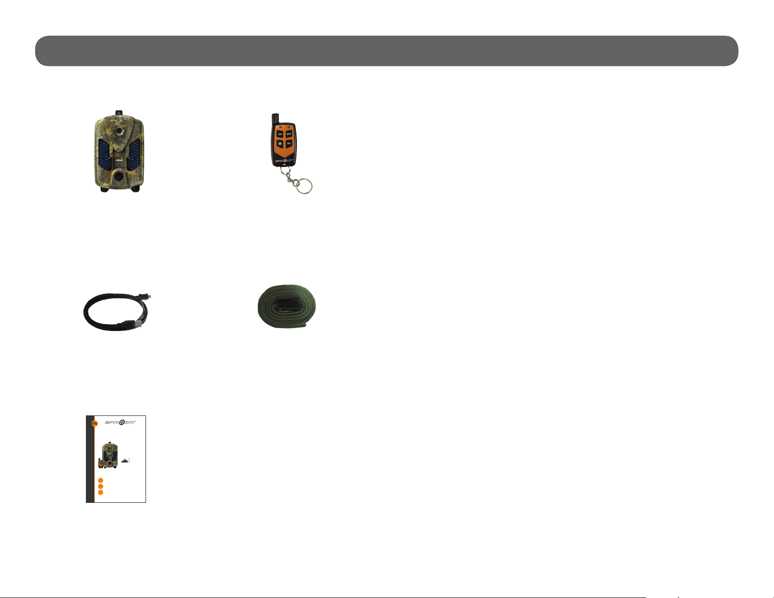
Package contents
In the box
Components
Installation
strap
USB
cable
Note: Memory card and batteries are sold separately.
Camera
Quick start
guide
Remote
control
BUSY LED
Viewing screen
Navigation buttons
Microphone
Power button
12V/Solar panel jack
USB port
SD card slot*
Built-in speaker
Photo lens
Invisible LEDs
Test light
Battery case
Detection lens
Mounting bracket
Slot for installation strap
Tripod mount
Cable lock hole
1
2
3
4
5
6
7
8
9
12
13
14
15
16
17
18
We recommend the use of new batteries to ensure a
maximum performance of the camera. Rechargeable AA
batteries are not recommended.
3. INSERT THE MEMORY CARD
Insert an SD/SDHC memory card (up to 32
GB capacity) in the card slot, gold contacts
facing up. The card is inserted correctly
when a click is heard.
Before inserting or removing a memory
card, always turn off the camera to
prevent loss or damage of the photos already
recorded.
4. TO USE THE REMOTE CONTROL
A. Turn on the camera.
B. Set the REMOTE CONTROL option to "On".
(Main menu Settings General)
C. Return to the main menu of the camera.
D. Press simultaneously the ON and FN buttons of the
remote control. The red and green lights will ash a
few moments before turning on and then, turning
off. If the lights are ashing constantly, it means
that the synchronization did not work. Try again.
1. REMOVE CAMERA FROM THE MOUNTING BRACKET
A. Push the tab to release the camera from
the mounting bracket.
B. Remove the camera.
2. CHOOSE A POWER SOURCE
In order to get best results and longer battery life, we
recommend the use of an external 12-volt source.
Getting started
10
11
*No SIM card slot for HAWK model
1
2
3
5
4
6
8
7
9
10 11 12 13 14
15 1716
18
A.
B.
ON/OFF
Buttons
Allows the user to enable or disable remotely the
detection of the camera.
CAMERA
Button
Allows the user to take photos or videos (up to
500ft).
Lithium battery pack
LIT-09/LIT-C-8
6 alkaline AA
batteries
or
2
1
Opening the
battery compatment
SPYPOINT
camera
USB
cable
P INTSPY INTPSPY
Quick start guide
Surveillance
camera
HAWK
www.spypoint.com
under Support section
1-888-779-7646
tech@spypoint.com
v1.0
RC-1
remote control
Installation
strap
Quick start
guide
4
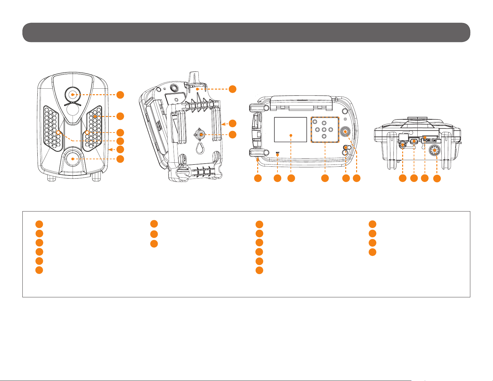
Components
Photo lens
1
Invisibles LEDs
2
Test light
3
Light sensor
4
Battery case
5
Fresnel lens
6
1
7
2
8
3
9
4
5
6
16 17 18
19
7
Mounting bracket
Slot for installation strap
8
Tripod mount
9
1210 1411 13 15
10
Cable lock hole
11
BUSY LED
12
Viewing screen
13
Navigation buttons
14
Microphone
15
Power button
16
12V/Solar panel jack
17
USB port
18
SD card slot *
19
Built-in speaker
*
No SIM card slot for HAWK model
5
Components
1 Photo lens Image sensor and infrared lter.
2 Invisible LEDs Night lighting to obtain black and white photos
and videos.
3 Test light Flashes in TEST mode when there is detec-
tion and ashes 60 seconds in PHOTO/VIDEO
mode to allow the user to leave without being
photographed or recorded.
4 Light sensor Allows the lighting of the LEDs panel at night.
5 Battery case Case for AA batteries or a rechargeable
lithium battery pack (p.7).
6 Fresnel lens Expands the detection area and increases the
sensitivity of the camera’s motion sensor.
7 Mounting bracket Removable support to install the camera
(p.8).
8 Slot for installation
strap
9 Tripod mount Standard ¼-20" tripod mount.
10 Cable lock hole Allows the user to install a CL-6FT cable lock,
11 BUSY LED Lights up during a detection when TEST mode
12 Viewing screen Allows the user to access the main menu and
Allows the user to install the camera using
the installation strap included (p.9).
sold separately (p.16).
is activated (p.8).
view photos/videos (p.9).
13 Navigation buttons Buttons to set the camera (p.11).
14 Microphone Records sound in video mode (p.12).
15 Power button Press the button to turn on or off the camera.
16 1) 12V power jack
2) Solar panel jack
17 USB port To transfer photos/videos to a computer
18 SD card slot An SD card is required to record photos/
19 Built-in speaker Allows the user to hear the sound when
1) This camera can be powered from an
external 12-volt DC input such as a 12V
battery or a 12V adapter, each sold
separately (p.7).
2) Allows the user to connect a solar panel
(SP-12V) to maintain the charge of the
lithium battery pack (LIT-09/LIT-C-8),
sold separately (p.7).
(p.13).
videos (p.8).
viewing videos.
6

Power
The battery level is shown in the bottom right corner of the screen when
the camera is in TEST mode. When a single line remains, the camera will
continue to take photos but we strongly recommend to change the AA
batteries or charge the lithium battery pack before they are empty. If a
video is being recorded and the battery level reaches 0%, the camera saves
the le before shutting down.
AA BATTERIES
This camera requires 6 AA batteries (1.5V). The
use of alkaline or lithium batteries is strongly
recommended. During the installation of the AA
batteries, the LIT-09 CHARGER option located in
the GENERAL SETTINGS menu should be "Off".
Insert the batteries as indicated inside the battery
case. Battery polarity must be followed.
Please note that the voltage of rechargeable
AA batteries (1.2V) is insufcient to power
the SPYPOINT camera. We also recommend
the use of new batteries to ensure maximum
performance of the camera.
LITHIUM BATTERY PACK
This SPYPOINT camera can be powered by a
rechargeable lithium battery pack LIT-09/LITC-8 (sold separately, p.15). This type of battery is less affected by cold temperatures and
lasts up to 3 times longer than alkaline batteries.
During the installation of the lithium battery, the
LIT-09 CHARGER option located in the GENERAL
SETTINGS menu should be "On".
EXTERNAL (12V)
This camera can also be powered by an external 12-volt DC input such as a
12-volt battery (KIT-12V, BATT-12V or KIT6V/12V) or a 12-volt adapter
(AD-12V), each sold separately (p.15). During the installation of a 12-volt
connection, the LIT-09 CHARGER option located in the GENERAL SETTINGS
menu should be "Off" (the AA batteries can remain safely inside the camera).
If combined with a lithium battery pack, the LIT-09 CHARGER option should
be "On". For available accessories, see p.15.
In order to get best results and longer battery life, we recommend the
use of an external 12-volt source.
SOLAR PANEL
This camera also offers the possibility to connect a solar panel (SP-12V sold
separately, p.15) to maintain the charge of the lithium battery pack
(sold separately, p.15). While installing the rechargeable lithium battery
pack, the LIT-09 CHARGER option located in the GENERAL SETTINGS menu
should be "On" to activate the charging system of the solar panel.
LIT-09 charger option (depending on the power source):
Power source LIT-09 charger option
• 6AA
• 12V
• 12V + 6AA
• LIT-09*
• 12V + LIT-09*
• Solar panel + LIT-09*
OFF
ON
* Rechargeable lithium battery pack, sold separately (LIT-09) or with a
charger (LIT-C-8).
7

Memory card/BUSY LED/Mounting bracket
MEMORY CARD
A memory card is required to record photos and videos. The camera is
compatible with SD/SDHC memory cards, up to 32 GB capacity (sold
separately, p.15).
When the camera is turned on and no memory card is used, the camera
beeps. In TEST mode, the screen displays "Insert Memory Card".
Here is a table of the approximate number of photos and length of videos
that can be recorded with different memory card capacities. Many photo
and video resolutions are noted, see those corresponding to the camera.
Note: This SPYPOINT camera is equiped with continuous le
recording. When the memory card is full, the camera will continue to record
photos or videos by deleting the rst recorded les.
4 GB 8 GB 16 GB 32 GB
Photo
3 MP 4100 8200 16400 32800
4 MP 3800 7600 15200 30400
5 MP 3400 6800 13600 27300
6 MP 3200 6300 12600 25300
7 MP 2700 5500 10900 21800
8 MP 2400 4800 9500 19000
10 MP 1900 3800 7600 15200
12 MP 1600 3200 6300 12600
Video
320 x 240 4 h 8 h 16 h 32 h
640 x 480 2h10 4h10 8h20 16h40
1280 x 720 40 min 1h20 2h40 5h20
INSERTING THE MEMORY CARD
Insert an SD/SDHC memory card (up to 32 GB
capacity) in the card slot , gold contacts facing up.
The card is inserted correctly when a click is heard.
Before inserting or removing a memory card,
always turn off the camera to prevent loss or
damage of the photos already recorded.
REMOVING THE MEMORY CARD
Lightly press the memory card into the camera once to pop it out of the slot
and remove it.
BUSY LED
The BUSY light, located below the screen, lights up in TEST mode at the
same time as the test light (located in front of the camera).
MOUNTING BRACKET
To remove the camera from the mounting bracket:
1.
2.
1. Push the tab to release the camera from the mounting
bracket.
2. Remove the camera.
8

Settings
Use the and buttons to navigate in the interface and modify the selection,
the OK button to select and the button to return to the previous menu.
PHOTO
Allows the user to take photos. When the PHOTO mode is selected, the
test light in front of the camera will ash for 60 seconds to allow the user to
leave the area without being photographed.
VIDEO
Allows the user to take videos. When the VIDEO mode is selected, the
test light in front of the camera will ash for 60 seconds to allow the user to
leave the area without being recorded.
TEST
Allows the user to test the detection system of the camera. When the
TEST mode is selected, no photo or video is recorded. Walk perpendicularly in
front of the camera. When the camera detects a movement, the busy light and
the test light blink to indicate that normally, a photo or video would have been
recorded. If the system does not detect the movement, increase the detection
distance using the "Sensitivity" option in the settings menu. Realignment
of the camera can also be required. In TEST mode, it is possible to take a
photo by pressing the OK button. The photo is saved and appears in the
VIEW mode.
INSTALLATION WITH THE SUPPLIED STRAP
Use the mounting bracket slot for installation strap to x the camera. The
dimensions of the strap (included) is 1" X 60".
VIEW
Allows the user to view or delete recorded photos and videos on the
camera screen.
• Viewing with the screen of the camera:
When the VIEW mode is selected, the latest photo or video recorded
appears on the screen automatically. Press or to view next or
previous images. Press to zoom in and to zoom out. When the zoom
is activated, press OK to move the image by using or . Press
OK again then to return to normal view.
Press OK to view the different options available:
Play: Allows the user to play or pause the video on the screen
(this option is available only for videos).
View date/time: Allows the user to view the date and time printed on
the photo.
Protect: Allows the user to protect a photo or video to prevent it
from being deleted by selecting "Erase All".
Erase one: Allows the user to erase the photo or the video seen on
the screen from the memory card.
Erase all: Allows the user to erase from the memory card all stored
photos and videos, with the exception of protected les.
Format: Allows the user to format the memory card and delete
all protected photos and videos.
Exit: Allows the user to exit the menu to return to the viewing
screen.
Recommended installation height: about 3 feet above the ground.
Do not place the camera facing the sun.
Note: The number of yellow stars that appear to the right of the screen
corresponds to the resolution of the photos.
=Low resolution =Medium resolution =High resolution
SETTINGS
Sets the advanced options of the camera (see p.10 for details).
9

Settings
Schedule:
Allows the user to set the operation period of the camera for each day
of the week. The start and stop time programmed hours are the hours
during which the camera is in action and records photos or videos. For
example, if the user selects "15:00" start time and "19:00" stop time
on Mondays, the camera will only detect for that period of time and will
stay inactive for the remaining hours. Each day has to be congured
independently.
For a 24 hour activation, the same start and stop times must be entered
for each day of the week (example: 00:00 as start time and 00:00 as stop
time. These hours are the basic settings of the camera.)
Note: The hours are recorded over a 24-hour period. For example, 5pm
is 17:00 (00:00 means midnight).
Delay:
(10s/1m/3m/5m/10m/15m/30m)
Allows the user to choose the time interval between each detection before
the camera records the next photo or video. A longer delay minimizes the
number of photos taken and maximizes the battery life. A shorter delay
maximizes the number of photos taken but requires more battery power.
The shorter times interval are recommended when the camera is used for
security purposes.
Multi-shot:
(1/2/3/4/5/6/7/8/9/10 consecutive shots)
Takes up to 10 consecutive shots at each detection, with a 10-second
delay between each photo. This option allows the user to get up to 10
photos from different angles when the camera is in PHOTO mode.
Video length:
(10s/30s/60s/90s)
Allows the user to select the duration of the recording when the camera
is set in VIDEO mode.
Photo rst:
When this option is enabled, a photo is taken immediately before each
video.
Note: The le name of the photo corresponds to the digit before the video
le name. For example, if the name of the photo is PICT001, the name of
the video will be PICT002.
Language:
(English/Français/Deutsch/Italiano/Español)
Allows the user to select a language for the camera menus.
Sensitivity:
(Low/Medium/High)
Allows the user to choose the detection sensitivity of the camera. A higher
sensitivity allows the user to take more photos.
The camera will only detect sources of heat in movement. Make sure to
have the least possible objects in front of the camera during the positioning.
This prevents the camera of taking photos when oriented towards the sun
while an object moves in front of the camera (e.g. a branch).
Date:
(MM/DD/YY, DD/MM/YY)
Allows the user to set the date as Month/Day/Year or as Day/Month/Year.
Time:
Allows the user to set the time as Hour/Minute.
10

Settings
Info on photos:
(Yes/No)
Allows the user to have date, time, temperature and moon phases printed
on the photos.
New moon:
Waxing Crescent:
First Quarter:
Waxing Gibbous:
Full moon:
Waning Gibbous:
Last Quarter:
Waning crescent:
Temperature:
(°C/°F)
Allows the user to select the temperature display.
Time lapse:
(Off/30s/1m/3m/5m/15m/30m/1h)
Allows the camera to take photos at regular preset intervals. For example,
if the option "5m" is selected in the TIME LAPSE mode, the camera takes
a photo every 5 minutes during the period of operation (Schedule) even if
there is no detection. This option allows the user to obtain photos of game
outside the detection range of the camera.
Remote control (RC-1):
(On/Off)
Allows the user to use the RC-1 remote control which works with the
REMOS wireless technology (sold separately, p.20). The remote control
allows to activate/deactivate the detection of the camera and to remotely
take a photo/video in an area of 500 ft.
Wireless sensor (MS-1):
(Off/1/2/3/4/5/6/7)
Allows the camera to be triggered wirelessly by one or more MS-1 devices
through the REMOS wireless technology, sold separately (p.16).
IR-Booster:
(On/Off)
Allows the camera to trigger, up to a distance of 50ft, one or more
IR-BOOSTER infrared lighting devices without the use of an additional
transmitter through the REMOS wireless technology. Sold separately,
p.16.
REMOS TECHNOLOGY
The cameras compatible with the REMOS technology (wireless functionnalities)
can be combined with:
• RC-1 :Remote control
Allows the user to control the camera remotely.
Note: The TIME LAPSE mode only applies for photos, not videos. When
the TIME LAPSE mode is selected, the DELAY option and the MULTI-SHOT
mode are disabled.
• MS-1 :Wireless sensor
Allows the user to trigger the camera remotely.
• IRB-W-B : Infrared Booster
Used to optimize the infrared lighting to accentuate the quality of night
photos and videos.
See SETTINGS (p.9) and AVAILABLE ACCESSORIES (p.15) sections
for more details.
The optional steel security box (SB-PRO) affects the wireless functionalites of products compatible with REMOS technology. The wireless
transmission of photos from the cameras to the controller is also affected.
11

Sound recording
The SPYPOINT camera offers the possibility to record sound in VIDEO mode.
When the VIDEO mode is selected, the camera automatically records the
sound. Under the camera, there is a rubber cap with the inscription MIC. If
the user does not want to record the sound, the rubber cap needs to stay in
place. If sound recording is required, the user must lift the rubber cap and
turn it slightly so that the microphone receiver is completely cleared (See
gure below).
12

File transfer to a computer
To transfer photos/videos to a computer:
1. Turn on the camera.
Note that the camera has to be turned on in order for the computer to
recognize the SD card.
USB
2. Connect the USB cable from the camera to a computer.
It is recommended to use the supplied cable.
3. The computer will detect the camera and install the driver automatically.
4. Click on "My Computer" and select "Removable Disk".
5. Then click on "DCIM" and "100DSCIM" to nd all recorded photos and
videos.
6. Drag or save the les to the desired location.
Taking the memory card (sold separately, p.15) out of the camera and
inserting it into the computer slot will achieve the same results.
13

Troubleshooting
TROUBLESHOOTING
Problem Possible solutions
Impossible to
turn on the
camera
The screen of the
camera turns off
The camera beeps • Insert a memory card (p.8).
The camera does
not respond
Impossible to
take photos/
videos
No person/animal
on photos
• Verify if there are batteries in the camera.
• Verify if the batteries are correctly installed (p.7).
• Verify if the LIT-09 charger option is set accordingly
to the power source (p.7).
• Install the latest update (available on www.spypoint.
com under SUPPORT section).
• Replace alkaline batteries or recharge the lithium
battery pack.
• The camera may be set to PHOTO or VIDEO mode
and the screen turns off after a period of 60 seconds
in order to preserve battery life.
• The camera automatically resets itself to PHOTO or
VIDEO mode (depending of the latest mode used
or selected) after 2 minutes of inactivity on the main
menu.
• To return to the screen, turn off the camera and turn
it on again.
• Remove the batteries and reinstall them (p.7).
• Replace alkaline batteries or recharge the lithium
battery pack.
• Verify if there are batteries in the camera.
• Replace alkaline batteries or recharge the lithium
battery pack.
• Verify if the camera is turned on.
• Sunrise or sunset can trigger the sensor. Camera
must be re-orientated.
• At night, the motion detector may detect beyond the
range of the IR illumination. Reduce sensibility
setting (p.10).
• Small animals may trigger the unit. Reduce sensibi lity setting (p.10) and/or raise height of camera.
• Motion detector may detect animals through foliage.
• If a person or animal moves quickly, it may move out
of the camera’s eld of view before the photo is
taken. Move the camera further back or redirect the
camera.
• Make sure the mounting post or tree is stable and
does not move.
Red light in front
of the camera
blinks
The computer
does not
recognize the
camera
• Camera is set in TEST mode.
• Camera is set in PHOTO or VIDEO mode. The red
light in front of the camera ashes for 60 seconds to
allow the user to leave without being photographed
or recorded.
• Verify if the camera is properly connected to the
computer using the USB cable (p.13).
ERROR MESSAGES
Error message Possible solutions
Insert memory
card
Card error
Low battery
No image
Protected le
14
The use of a memory card is required to record photos
and videos.
The camera cannot access the memory card.
• Turn off the camera and turn it on again
• Remove the memory card and insert it again.
• Verify if the gold contacts are clean.
• Format the memory card.
Appears on the screen just before the camera turns
off. Recharge the batteries or insert new ones. Always
verify the battery level before using the camera.
There are no les to view. Verify if the memory card
contains photos/videos.
It is impossible to delete the le because it is protected.
To delete this le and all the others, just format the
memory card.

Available accessories
P INT
INTP
Memory Card
Carte Mémoire
HIGH SPEED/HAUTE VITESSE
/
R
F
N
To obtain more information on the available accessories, go to
www.spypoint.com. Here are the main accessories available:
POWER
12V DC Power cable
#CB-12FT, 12 ft power cable with
alligator clips at one end to connect
a 12V battery to a camera.
12-volt Adaptor
#AD-12V, AC adaptor (6V to 12V).
Powers the camera from an electrical outlet.
Lithium battery pack
#LIT-09, Additional rechargeable
lithium battery pack. Fits most
SPYPOINT products.
Lithium battery pack & charger
#LIT-C-8, Rechargeable lithium
battery pack and AC charger with
charge indicator light. Fits most
SPYPOINT products.
Rechargeable 6V-12V battery,
charger & housing kit
#KIT6V-12V, Universal kit with
two 6V rechargeable batteries
(2.8Ah), with 6V (5.6Ah) and 12V
(2.8Ah) output conguration and
AC charger. Water resistant ABS
plastic case, 12 ft power cable
and strap included. Camo pattern.
Compatible with all SPYPOINT products equipped with a 12V power
jack.
Rechargeable 12V battery,
charger & housing kit
#KIT-12V, 12-volt 7.0Ah rechargeable battery with a water
resistant ABS plastic case, AC
charger, 12 ft power cable (#PW12FT) and carrying strap included.
Compatible with all SPYPOINT
products equipped with a 12V
power jack.
Remote control
#RC-1, Four button wireless
remote control. Works with all
cameras compatible with REMOS
technology (up to 500 ft). Battery
included.
MEMORY CARD
SPY
SPY
Solar panel
#SP-12V, Solar panel with
adjustable steel mounting kit.
Maintains the charge of the lithium
battery pack directly into compatible
devices. Can also be combined
with any 12-volt battery. 9 ft
power cable.
Spare power cable
#PW-12FT, Spare 12 ft power
cable, to connect the camera to
the KIT-12V.
SD Memory card 8GB
#SD-8GB, SDHC memory card
Rechargeable 12V battery &
8 GB, High speed Class 6.
charger set
#BATT-12V, 12-volt 7.0Ah rechargeable battery and AC charger to
power the camera.
15

Available accessories
INSTALLATION AND SECURITY
Cable lock
#CL-6FT, 6 ft cable lock ts all
SPYPOINT cameras.
Camera mount
#MA-360, Adjustable mounting
arm, ts all cameras that have a
standard ¼-20" tripod mount. It
can rotate 360° and tilt approx +/90°. Also available in black.
Steel security box
#SB-PRO, Steel box to secure
the camera against theft. It also
protects it from breakage caused
by bears or other animals. Fits
SPYPOINT cameras of 62 LED.
Also available in black.
INFRARED BOOSTER
Invisible LEDs IR-Booster
#IRB-W-B, 100 invisible LEDs
(completely invisible to the naked
eye) wireless infrared module
that allows the user to amplify
the infrared lights at night for
clearer shots. Compatible with
REMOS technology. When used
with REMOS compatible cameras,
the transmitter is not necessary.
OTHERS ACCESSORIES
IR-Booster
#IRB-W, 100 LED wireless infrared module that allows the user to
amplify the strength of the infrared lights for clearer night shots.
Tripod
#TP-CAM, SPYPOINT Lightweight
tripod, in black aluminum, with a
unique anchor system and a removable quick release plate. Max.
height: 4.9 ft (1.5 m), min. height:
1.7 ft (0.5 m), max. load weight:
11 lbs (5 kg). Fits most SPYPOINT
products.
REMOS Wireless motion
sensor
#MS-1, Wireless motion sensor
that allows the user to trigger the
camera remotely, up to 500 ft
away. Works with all cameras compatible with REMOS technology.
Requires 1 alkaline 9V battery or a
12V power supply (not included).
Also available in black.
16

SPECIFICATIONS (HAWK)
Photo recording
Photo resolution Full HD
File format JPG
Time lapse mode Predened intervals from 30 s to 1 h
Multi-shot mode Up to 10 photos per detection
Info on photos Date, time, temperature (°C/°F) and
moon phase
Capture mode Color by day, black and white by night
Video recording
Video resolution 1280 x 720 (HD 720p)
File format AVI
Sequence length Adjustable from 10 to 90 s
Capture mode Color by day, black and white by night
Audio
Sound recording
Mono
(automatically recorded in video
mode when rubber cap is removed)
Memory storage
Support •Internal memory: none
•External memory: SD/SDHC card
(up to 32 GB)
Viewing
Built-in screen 2.4" LCD
Computer output USB 2.0
Power source
Accessories sold separately, p. 15
Alkaline or lithium batteries 6 x AA
Lithium battery pack Rechargeable battery pack
(LIT-09/LIT-C-8)
External (12V jack) 12V battery (KIT6V-12V, KIT-12V, BATT-
12V) or 12V adapter (AD-12V)
Solar panel Solar panel (SP-12V) combined with
rechargeable battery pack (LIT-09/LIT-
C-8)
Detection system
Motion sensor PIR
Delay between each detection Adjustable from 10 sec to 30 min
Night time illumination system
LEDs 62 LEDs
Type Invisible LEDs
Exposure Automatic infrared level adjustment
Dimensions
4.3" W x 6.8" H x 3" D
Wireless
REMOS
Technology This camera is compatible with the
REMOS Technology.
Recommendations
Operating temperature (-4 °F to +122 °F) (-20 °C to + 50 °C)
Storage temperature (-22 °F to +167 °F) (-30 °C to + 75 °C)
17

Limited warranty and repair
This SPYPOINT product designed by GG Telecom, is covered by a one (1)
year warranty on material and workmanship starting from the original date
of purchase. The sales receipt is the client’s proof of purchase and must be
presented if warranty service is needed. This warranty will be honored in the
country of purchase only.
This warranty does not cover any GG Telecom product which has been
subjected to misuse, neglect and accidents or has been improperly used
or maintained. In addition, this warranty is not applicable for all products
purchased online from an unauthorized dealer. Any modication or tampering of the product will affect its operation, performance, durability and
voids this warranty.
INSTRUCTIONS FOR REPAIR SERVICE
GG Telecom will repair the product without charge or replace it at its discretion with an equivalent product, if it has a manufacturing defect covered by
the warranty described previously. GG Telecom will pay the shipping costs
only for the return of the products covered by the warranty. The shipping
costs for an item sent will be assumed by the customer.
Repairs for damages not covered by the warranty will be subject to a
reasonable charge. The customer will pay all shipping costs.
1. BEFORE sending a product for repair, the costumer is welcomed
to contact GG Telecom technical support team at 1-888-779-7646
or tech@spypoint.com and to clearly describe the problem and give
a phone number where she or he can be reached. It happens
regularly that some problems can be solved over the phone.
2. If a product needs to be sent, an RMA number will be given to the
customer (Return Merchandise Authorization).
3. The original receipt or a copy must be sent along with the
package.
4. The RMA number must be written on the outside of the package
and sent to:
CANADA United States
GG Telecom GG Telecom
120 J.Aurèle-Roux 555 VT route 78
Victoriaville, QC Swanton, Vermont
G6T 0N5 05488
IMPORTANT: Under no circumstances will GG Telecom accept returned
products without a Return Material Authorization number (RMA). It is
essential to contact GG Telecom before making a return.
The customer is liable for loss or damage to the product that may occur
during the transport to GG Telecom. We recommend the use of a traceable
method of shipping to ensure protection.
WWW.SPYPOINT.COM
18
 Loading...