


force
v1.0
USER GUIDE
Models:
FORCE-10
FORCE-11D
& comparable
ULTRA COMPACT
TRAIL CAMERA
1-888-779-7646
support.spypoint.com
tech@spypoint.com
2
FORCE
THANK YOU FOR CHOOSING A SPYPOINT PRODUCT.
This manual will guide you through all the features of your device
so that you will get optimal use out of your SPYPOINT product. Our
priority is to provide outstanding customer service. If you need
support for your product, please contact the SPYPOINT technical
support or visit our website.
CONTACT
1-888-779-7646
tech@spypoint.com
www.spypoint.com
ABOUT US
GG Telecom’s mission is to oer products that are easy
to use, innovative, aordable and of exceptional quality.
Our SPYPOINT products are mainly used for hunting and
residential/commercial surveillance. They are distributed and
shipped all over the world and the market never stops growing.
Prosperous and respected, GG Telecom is a company that constantly
keeps abreast of new technologies and listens to its customers to
deliver cutting-edge products with practical solutions that improve
hunting and outdoor activities.
JOIN THE SPYPOINT COMMUNITY
NON-CELLULAR CAMERAS
Visit mySPYPOINT.com to create your free basic account.
facebook.com/SPYPOINT
twitter.com/SPYPOINTcamera
youtube.com/SPYPOINTtrailcam
CELLULAR CAMERAS
Visit mySPYPOINT.com to learn more about the dierent accounts
available. For the latest version of the activation procedure, go to
support.spypoint.com/activation.
mySPYPOINT.com is an online camera & photo management
system. This incredible tool for hunters is available for all SPYPOINT
cameras.

3
FORCE
Components ................................................................................. 4
Specications
FORCE-10 ...................................................................................... 6
FORCE-11D .................................................................................... 7
Power ........................................................................................... 8
Memory card & Busy LED .............................................................. 9
Settings .......................................................................................10
Installation & Mounting bracket ..................................................14
File transfer to a computer ..........................................................15
Available accessories ...................................................................16
Troubleshooting ..........................................................................17
Limited warranty .........................................................................18
Repair service ..............................................................................18
Regulation ...................................................................................19
Table of contents
4
FORCE
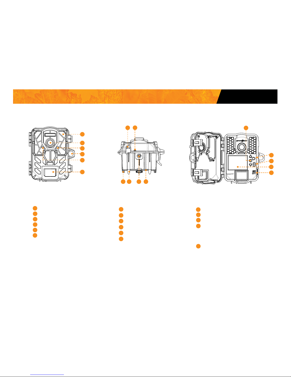
LEDs
Photo lens
Test light
Cable lock hole
Light sensor
Motion sensor
1
2
3
4
5
6
7
8
12V jack
Microphone
BUSY LED
Slot for installation strap
Tripod mount
Battery case
9
10
11
12
OK button
Navigation buttons
ON / OFF switch
Conguration screen
(FORCE-10 & comparable)
Viewing screen
(FORCE-11D & comparable)
SD card slot
13
14
15
16
17
Components
1
2
3
4
5
6
9
8
7
10 11 12
13
14
15
16
17

5
FORCE
1 LEDs Night lighting to obtain black and white photos
and videos.
2 Photo lens Image sensor and infrared lter.
3 Test light Flashes in TEST mode when there is detec-
tion and ashes 60 seconds in PHOTO/VIDEO
mode to allow the user to leave without being
photographed or recorded.
4 Cable lock hole Allows the user to install a CL-6FT cable lock,
sold separately.
5 Light sensor Allows the lighting of the LEDs panel at night.
6 Motion sensor Expands the detection area and increases the
sensitivity of the camera’s motion sensor.
7 1) 12V power jack 1) This camera can be powered from an
external 12-volt DC input such as a 12V
battery or a 12V adapter, each sold
separately.
8 Microphone Records sound in video mode.
9 BUSY LED Lights up when TEST mode is activated.
10 Slot for installation
strap
Allows the user to install the camera using
the installation strap included.
11 Tripod mount Standard ¼-20" tripod mount.
12 Battery case Case for AA batteries or a rechargeable
lithium battery pack.
13 OK button Allows the user to make a selection.
14 Navigation buttons Buttons to set the camera.
15 ON/OFF button Allows the user to turn on/o the camera.
16 Conguration screen
(FORCE-10 & comparable )
Allows the user to congure the settings of the
camera through the main menu.
Viewign screen
(FORCE-11D & comparable)
Allows the user to access the main menu and
view photos/videos.
17 SD card slot An SD card is required to record photos/
videos.
Components

6
FORCE
Photo recording
Photo resolution 10 MP
File format JPG
Time lapse mode Predened intervals from 30 s to 1 h
Multi-shot mode Up to 6 photos per detection
Stamp (only on photos) Date, time, temperature (°C/°F) and
moon phase
Capture mode Color by day, black and white by night
Video recording
Video resolution 1280 x 720 (HD 720p)
File format AVI
Sequence lenght Adjustable from 10 to 90 s
Capture mode Color by day, black and white by night
Audio
Sound recording
(automatically recorded in video
mode)
N/A
Memory storage
Support •Internal memory: none
•External memory : SD/SDHC card
(up to 32 GB)
Viewing
Built-in screen ACL 2’’
Power source
Accessories sold separately, p.18
Alkaline or lithium batteries 6 x AA
Lithium battery pack Rechargeable battery pack
(LIT-09/LIT-C-8)
External (12V jack) 12V battery (KIT6V-12V, KIT-12V,
BATT-12V) or 12V adapter (AD-12V)
Detection system
Motion sensor PIR
Detection angle 55°
Detection range Adjustable from 5 to 80 ft
Delay between each detection Adjustable from 10 s to 30 min
Night time illumination system
LEDs 42 LEDs
Type Low glow LEDs
Exposure Automatic infrared level adjustment
Optical eld of view
40°
Dimensions
3.8” W X 5.0” H X 3.2” D
Recommendations
Operating temperature (-30 °C to + 50 °C) (-22 °F to +122 °F)
Storage temperature (-40 °C to + 60 °C) (-40 °F to +140 °F)
Specications
FORCE-10

7
FORCE
Specications
Photo recording
Photo resolution 11 MP
File format JPG
Time lapse mode Predened intervals from 30 s to 1 h
Multi-shot mode Up to 6 photos per detection
Stamp (only on photos) Date, time, temperature (°C/°F) and
moon phase
Capture mode Color by day, black and white by night
Video recording
Video resolution 1280 x 720 (HD 720p)
File format AVI
Sequence lenght Adjustable from 10 to 90 s
Capture mode Color by day, black and white by night
Audio
Sound recording
(automatically recorded in video
mode)
Mono
Memory storage
Support •Internal memory: none
•External memory : SD/SDHC card
(up to 32 GB)
Viewing
Built-in screen ACL 2’’
Power source
Accessories sold separately, p.18
Alkaline or lithium batteries 6 x AA
Lithium battery pack Rechargeable battery pack
(LIT-09/LIT-C-8)
External (12V jack) 12V battery (KIT6V-12V, KIT-12V,
BATT-12V) or 12V adapter (AD-12V)
Detection system
Motion sensor PIR
Detection angle 55°
Detection range Adjustable from 5 to 80 ft
Delay between each detection Adjustable from 10 s to 30 min
Night time illumination system
LEDs 42 LEDs
Type Super low glow LEDs
Exposure Automatic infrared level adjustment
Optical eld of view
40°
Dimensions
3.8” W X 5.0” H X 3.2” D
Recommendations
Operating temperature (-30 °C to + 50 °C) (-22 °F to +122 °F)
Storage temperature (-40 °C to + 60 °C) (-40 °F to +140 °F)
FORCE-11D

8
FORCE
The battery level is shown in the bottom right corner of the screen when
the camera is in TEST mode. When a single line remains,the camera will
continue to take photos. However, we strongly recommend to change the
AA batteries or charge the lithium battery pack before they are empty. If a
video is being recorded and the battery level reaches 0%, the camera saves
the le before shutting down.
AA BATTERIES
This camera requires 6 AA batteries (1.5V). The
use of alkaline or lithium batteries is strongly
recommended.
To ensure maximum performance of the camera
and prevent battery leak, we recommend the
use of new batteries. Make sure to insert each battery
with the correct polarity. (Negative or at end agaist
the metal spring plate) Do not mix battery type - use
ALL alkaline or ALL lithium. Do not mix old and new
batteries. Rechargeable AA batteries are not recommended as the lower voltage they produce can cause
operational issues.
LITHIUM BATTERY PACK
This SPYPOINT camera can be powered by a rechargeable lithium battery pack LIT-09/LIT-C-8 (sold
separately). This type of battery is less aected by
cold temperatures and lasts up to 3 times longer
than an alkaline batteries.
EXTERNAL (12V)
This camera can also be powered by an
external 12-volt DC input such as a 12-volt
battery (KIT-12V, BATT-12V or KIT6V/12V) or a
12-volt adapter (AD-12V), sold separately.
Power
RECHARGEABLE 7.4 VOLT LI-ION POLYMER BATTERY 2.0 Ah
RECYCLE OR DISPOSE OF PROPERLY
Li-ion
Made in China
|
Fabriqué en Chine v2.3
www.spypoint.com
P INTSPY INTPSPY
Models: LIT-09: Battery only
LIT-C-8: LIT-09 Battery & charger
WARNING: To reduce risk of fire or burns,
- Do not attempt to open, disassemble, or service the battery pack.
- Do not crush, puncture, short external contacts, or dispose
of in fire or water.
ATTENTION: Pour réduire les risques de feu ou de brûlures,
- Ne pas essayer d’ouvrir, désassembler, ou de réparer la pile.
- Ne pas frapper, percer, court-circuiter les contacts externes
de la pile ou mettre dans le feu ni l’eau.
DC 12V

9
FORCE
MEMORY CARD
A memory card is required to record photos and videos. The camera is
compatible with SD/SDHC memory cards, up to 32 GB capacity (sold
separately, p.18).
When the camera is turned on and no memory card is used, the camera
beeps. In TEST mode, the screen displays "Insert Memory Card".
The percentage of used space on SD card appears in the top right corner
of the screen in TEST mode, and the number of photos left appears in the
bottom left corner.
Here is a table of the approximate number of photos and length of videos
that can be recorded with dierent memory card capacities. Many photo and
video resolutions are noted, see those corresponding to the camera.
Note: This SPYPOINT camera is equiped with continuous le recording.
When the memory card is full, the camera will continue to record photos or
videos by deleting the rst recorded les.
4 GB 8 GB 16 GB 32GB
Photo
3 MP 4100 8200 16400 32800
4 MP 3800 7600 15200 30400
5 MP 3400 6800 13600 27300
6 MP 3200 6300 12600 25300
7 MP 2700 5500 10900 21800
8 MP 2400 4800 9500 19000
9 MP 2200 4500 8900 18000
10 MP 1900 3800 7600 15200
11 MP 1700 3400 6700 13400
12 MP 1600 3200 6300 12600
Video
320 x 240 4 h 8 h 16 h 32 h
640 x 480 2h10 4h10 8h20 16h40
1280 x 720 40 min 1h20 2h40 5h20
Memory card / "BUSY" LED
INSERTING THE MEMORY CARD
Before inserting or removing a memory card, always turn o the camera to
prevent loss or damage of the photos already recorded. Also make sure that
the switch on the side of the card is not in the LOCK position.
Insert an SD/SDHC memory card (up to 32 GB capacity) in the card slot
with the label side facing upward. The card is inserted correctly when a click
is heard.
We suggest to format your SD card if it's been in another electronic
device to make sure you will have the maximum capacity of your
memory card.
REMOVING THE MEMORY CARD
Lightly press the memory card into the camera once to pop it out of the slot
and remove it.
BUSY LED
The BUSY light is located at the back of the camera and is covered by a rubber
cap. In order to see the BUSY light, the rubber cap has to be removed. It
is a diagnostic tool. It lights up when the camera starts, when the camera
records a le and in TEST mode at the same time as the test light (located
in front of the camera).

10
FORCE
Use the and buttons to navigate in the interface and modify the selection,
the OK button to select and the button to return to the previous menu.
START CAMERA
Allows the user to start the camera in either, PHOTO, VIDEO or TIME
LAPSE mode. When a mode is selected, the test light in front of the
camera will ash for 60 seconds and a countdown will appear on the
screen to allow the user to leave the area without being photographed.
DETECTION TEST
Allows the user to test the detection system of the camera. When the
DETECTION TEST mode is selected, no photo or video is recorded. Walk
perpendicularly in front of the camera. When the camera detects a
movement, the busy light and the test light blink to indicate that normally, a
photo or video would have been recorded. If the system does not detect the
movement, increase the detection distance using the "Sensitivity" option
in the settings menu. Realigning the camera can also be required. In TEST
mode, it is possible to take a photo by pressing the OK button. The photo is
saved and appears in the VIEW mode.
VIEW
(Force-11 & comparable only)
Allows the user to view or delete recorded photos and videos on the
camera screen.
9/9
1
2
3
1
Selected photo / total number of photos
2
The play icon indicates that this element is a video
3
The white outline indicates which photo is selected
Viewing with the screen of the camera:
When the VIEW mode is selected, the latest photos or videos recorded
appear as thumbnails on the screen. Press or to navigate this page,
and press OK to view a photo in large format. To view next or previous large
photo, press or . Press back to return to the thumbnail view.
When a large photo in opened, press OK to view the dierent options available:
Play: Allows the user to play or pause the video on the screen
(this option is available only for videos).
Zoom: Allows the user to zoom in or out.
Date and time: Allows the user to view the date and time printed on
the photo.
Protect: Allows the user to protect a photo or video to prevent it
from being deleted by selecting "Erase All".
Erase: Allows the user to erase the photo or the video seen on
the screen from the memory card.
Erase all: Allows the user to erase from the memory card all stored
photos and videos, with the exception of protected les.
Format: Allows the user to format the memory card and delete
all protected photos and videos.
Exit: Allows the user to exit the menu and return to the
viewing screen.
SETTINGS
Allows the user to the dierents settings on the camera. From PHOTO,
VIDEO, TIME LAPSE or GENERAL settings
Settings

11
FORCE
Settings
PHOTO SETTINGS
Sets the options of the PHOTO mode.
Delay:
(Instant/10s/1m/3m/5m/10m/15m/30m)
Allows the user to choose the time interval between each detection before
the camera records the next photo. A longer delay minimizes the number
of photos taken and maximizes the battery life. A shorter delay maximizes the number of photos taken but requires more battery power. The
shorter times interval are recommended when the camera is used for
security purposes.
Multi-shot:
(1/2/3/4/5/6 consecutive shots)
Takes up to 6 consecutive shots at each detection, with a 10-second
delay between each photo. This option allows the user to get up to 6
photos from dierent angles when the camera is in PHOTO mode.
TIME LAPSE SETTINGS
Sets the options of the TIME LAPSE mode.
Interval:
(30s/1m/3m/5m/15m/30m/1h)
Allows the camera to take photos at regular preset intervals. For example,
if the option "5m" is selected in the TIME LAPSE mode, the camera takes
a photo every 5 minutes even if there is no detection. This option allows
the user to obtain photos of game outside the detection range of the
camera.
Note: The TIME LAPSE mode only applies for photos, not videos. When
the TIME LAPSE mode is selected, the DELAY option and the MULTISHOT mode are disabled.
VIDEO SETTINGS
Sets the options of the VIDEO mode.
Delay:
(10s/1m/3m/5m/10m/15m/30m)
Allows the user to choose the time interval between each detection before
the camera records the next video. A longer delay minimizes the number
of videos taken and maximizes the battery life. A shorter delay maximizes
the number of videos taken but requires more battery power. The shorter
times interval are recommended when the camera is used for security
purposes.
Video length:
(10s/30s/60s/90s)
Allows the user to select the duration of the recording when the camera
is set in VIDEO mode.
Recommended settings
The camera can be congured for usage in trails. This situation usually
presents low activity level, fast subjects and a small number of photos is
expected. These settings increase the chances of capturing animals that
follow each other.
The camera can also be congured for usage at a feeder's site. This
situation usually presents high activity level, slow subjects and a large
number of photos is expected. These settings moderate the number of
photos taken while capturing overall activity on feeder's site.
Here is a table showing the suggested settings for each situation:
Trail Feeder
Delay Instant 5 min
Multi-shots 1 2-3
When these recommended settings are not adapted to the situation,
battery life can be aected.
Photo rst:
When this option is enabled, a photo is taken immediately before each
video.
Note: The le name of the photo corresponds to the digit before the
video le name. For example, if the name of the photo is PICT001, the
name of the video will be PICT002.

12
FORCE
Settings
GENERAL SETTINGS
Sets the general options of the camera.
Device name
Allows naming the camera with the electronic keyboard to identify it
clearly. This option is particularly useful for users with more than one
camera.
Language:
(English/Français/Deutsch)
Allows the user to select a language for the camera menus.
Date format:
(MM/DD/YY, DD/MM/YY)
Allows the user to set the date as Month/Day/Year or as Day/Month/Year.
Time format:
(12H/24H)
Allows the user to set to standard time or millitary time.
Date:
Allows the user to set the date
Time:
Allows the user to set the time
Sentitivity:
(Low/Medium/High)
Allow the user to choose the sensitivity of the motion sensor.
The camera will only detect sources of heat in movement. Make sure to
have the least possible objects in front of the camera during the positioning.
This prevents the camera of taking photos when oriented towards the sun
while an object moves in front of the camera (e.g. a branch).
Quality:
(Normal/High)
Allow the user to set the photo quality.
Info on photos:
(Yes/No)
Allows the user to have date, time, temperature and moon phases printed
on the photos.
New moon:
Waxing Crescent:
First Quarter:
Waxing Gibbous:
Full moon:
Waning Gibbous:
Last Quarter:
Waning crescent:
Start time:
Allows the user to set the start time of the motion detector.
Stop time:
Allows the user to set the stop time of the motion detector.

13
FORCE
Night mode:
Allows the user to set the best option for photos.
(Force-10 & comparable don't have the Blur reduction option)
Temp. units:
(°C/°F)
Allows the user to select the temperature display.
About the device:
Allows the user to displays system information:
- Software version number
- Hardware version number
- Model number
Factory reset:
Allows the user to restore the device to its original state.
illumination modes comparison* (Night modes)
optimal
MODE
IR-boost
MODE
blur reduction
MODE
Blur reduction
Battery life
Flash range

14
FORCE
Installation & Mounting bracket
INSTALLATION
Recommended installation height:
The camera should be installed at the same height as the animal’s mid-body.
Ideal installation for quality pictures & videos:
The targeted animal should be 25 feet / 7.5m away from the camera for a
better eld of view.
To get brighter pictures at night , you should have elements in the
background to reect back the IR ash to the camera.
Note that the camera should not directly be facing the sun to avoid back
lighting and false detection.
Make sure the front of the camera is free of any obstructions. The area
of installation should be cleared from branches or bushes. These could be
responsable for triggering false detections when combined with heat, reections and/or wind. Setting the sensitivity level of the camera too high can
also result in false detections by unwanted movement.
MOUNTING BRACKET
To remove the camera from the mounting bracket:
1. Push the tab to release the camera from the mounting bracket.
2. Remove the camera.
INSTALLATION WITH THE SUPPLIED STRAP
Use the mounting bracket or the camera slot for installation strap to x the
camera.
The dimensions of the strap (included) is 1" X 60".

15
FORCE
To transfer photos/videos to a computer:
• Turn OFF the camera.
• Remove the SD card from the camera.
• Insert the SD card into the computer slot, or use a memory card
adaptor.
• The computer will detect the card and install the driver automatically.
For a PC
Click on "My Computer" or «This PC» on your Desktop
Locate your device under "Removable Disk" and then click to access it.
Then click on "DCIM" and "100DSCIM" to nd all recorded photos and
videos.
Select the photos you want to copy. The easiest way is to select them all by
clicking on the Home tab and the Select all on the right-hand side. (You can
also press Ctrl and the ‘A’ key, or click the Edit menu and choose select all
in other versions of Windows)
Click the Copy icon on the left-hand side of the ribbon (or hold Ctrl and press
C). [NOTE: If you don't want to select all photos, hold down the Ctrl key
and click on the photos you do want to select before clicking the Copy icon]
Navigate to the folder in which you would like to store your images, or
create a new folder by click the New Folder button in the ribbon. (You can
also press Ctrl–Shift–N together to create a new folder, or right-click in some
empty space in the Pictures folder and choose New, then from the next
menu: Folder)
Type a name for your new folder, press Enter and then double-click on the
folder to open it.
From the Home tab, choose Paste (or hold Ctrl and press V). The photos will
be copied into the new folder.
File transfer to a computer
For a Mac
Click the Finder icon in the Dock.
Locate your device under the Devices tab and then click to access it.
Then click on "DCIM" and "100DSCIM" to nd all recorded photos and
videos.
Click Edit on the toolbar running along the top of the screen and then press
Select All to highlight every single images on the device. Select All is also
achievable by pressing the ⌘ and A key simultaneously on your keyboard.
Alternatively, if you do not wish to import all, you can individually highlight
the images you would like to transfer by holding ⌘ and clicking the le-
name.
Click Edit once again and then Copy (or ⌘ and C) to copy the highlighted
images.
Navigate to the folder in which you would like to store your images, or
create a new folder by right-clicking and pressing CTRL simultaneously, then
select New Folder from the menu.
Click Edit and then Paste (or ⌘ and V) to copy your chosen images from
your device to the selected folder.
Images may take several minutes to transfer depending on the le size and
the amount of images you are importing.
Once your images have transferred, click the Eject icon situated alongside
the name of your device and then unplug the device from your Mac.

16
FORCE
12-volt Adaptor
#AD-12V, AC adaptor (6V to 12V).
Powers the camera from an electrical outlet.
12V DC Power cable
#CB-12FT, 12 ft power cable with
alligator clips at one end to connect
a 12V battery to a camera.
Rechargeable 12V battery,
charger & housing kit
#KIT-12V, 12-volt 7.0Ah rechargeable battery with a water
resistant ABS plastic case, AC
charger, 12 ft power cable (#PW-
12FT) and carrying strap included.
Compatible with all SPYPOINT
products equipped with a 12V
power jack.
Lithium battery pack & charger
#LIT-C-8, Rechargeable lithium
battery pack and AC charger with
charge indicator light. Fits all SPYPOINT cameras.
Memory Card
Carte Mémoire
ULTRA HIGH SPEED/ULTRA HAUTE VITESSE
/
R
F
N
16 GB
SD Memory card 16GB
#SD-16GB, SDHC UHS-1 memory
card 16 GB, ultra high speed Class
10.
Available accessories
Cable lock
#CL-6FT, 6 ft cable lock ts all
SPYPOINT cameras.
Camera mount
#MA-360, Adjustable mounting
arm, ts all cameras that have a
standard ¼-20" tripod mount. It
can rotate 360° and tilt approx +/-
90°. Also available in black.
Steel security box
#SB-FORCE, Steel box to secure
the camera against theft. It also
protects it from breakage caused
by bears or other animals. Fits all
42 LED SPYPOINT cameras.
To obtain more information on other available accessories, go to
www.spypoint.com

17
FORCE
Issue Possible solutions
Impossible to turn
on the camera
• Verify if there are batteries in the camera.
• Verify if the batteries are correctly installed.
• Install the latest update (available on www.spy
point.com under SUPPORT section).
• Replace alkaline batteries or recharge the lithium
battery pack.
The screen of the
camera turns o
• The camera may be set to PHOTO or VIDEO mode
and the screen turns o after a period of 60 seconds
in order to preserve battery life.
• The camera automatically resets itself to PHOTO or
VIDEO mode (depending of the latest mode used
or selected) after 2 minutes of inactivity on the main
menu.
• To return to the screen, turn o the camera and turn
it on again.
The camera beeps • Insert a memory card.
The camera does
not respond
• Remove the batteries and reinstall them.
• Replace alkaline batteries or recharge the lithium
battery pack.
Impossible to
take photos/
videos
• Verify if there are batteries in the camera.
• Replace alkaline batteries or recharge the lithium
battery pack.
• Verify if the camera is turned on.
Red light in front
of the camera
blinks
• Camera is set in TEST mode.
• Camera is set in PHOTO or VIDEO mode. The red
light in front of the camera ashes for 60 seconds to
allow the user to leave without being photographed
or recorded.
No person/animal
on photos
• Sunrise or sunset can trigger the sensor. Camera
must be re-orientated.
• At night, the motion detector may detect beyond the
range of the IR illumination. Reduce sensibility
setting.
• Small animals may trigger the unit. Reduce sensibi-
lity setting and/or raise height of camera.
• Motion detector may detect animals through foliage.
• If a person or animal moves quickly, it may move out
of the camera’s eld of view before the photo is
taken. Move the camera further back or redirect the
camera.
• Make sure the mounting post or tree is stable and
does not move.
Error message Possible solutions
Insert memory
card
The use of a memory card is required to record photos
and videos.
Card error
The camera cannot access the memory card.
• Turn o the camera and turn it on again
• Remove the memory card and insert it again.
• Verify if the gold contacts are clean.
• Format the memory card.
Low battery
Appears on the screen just before the camera turns
o. Recharge the batteries or insert new ones. Always
verify the battery level before using the camera.
No image
There are no les to view. Verify if the memory card
contains photos/videos.
Protected le
It is impossible to delete the le because it is protected.
To delete this le and all the others, just format the
memory card.
Troubleshooting

18
FORCE
LIMITED WARRANTY
This SPYPOINT product designed by GG Telecom, is covered by a one (1)
year warranty on material and workmanship starting from the original date
of purchase. The sales receipt is the client’s proof of purchase and must be
presented if warranty service is needed. This warranty will be honored in the
country of purchase only.
This GG Telecom warranty does not apply: (a) to consumable parts, including but not limited to batteries, which performance is designed to decrease
over the course of time; (b) to damage caused by misuse, use with another
product, neglect, accidents, liquid contact, re, earthquake or any other external cause; (c) to GG Telecom products that have been purchased online
from an unauthorized dealer; (d) to products that have had any modication
or tampering; (e) to cosmetic damage including but not limited to scratches
and broken plastic; (f) to damage caused by operating the GG Telecom product outside of GG Telecom’s recommendations.
INSTRUCTIONS FOR REPAIR SERVICE
GG Telecom will repair the product or replace it at its discretion with an
equivalent product without charge if covered by the warranty described
previously. The shipping fees for an item sent will be assumed by the
customer. GG Telecom will then pay for the return of the product covered
by the warranty.
For a product not covered by the warranty, the repair will be subject to a
reasonable charge and the customer will also assume all shipping costs.
IMPORTANT: Under no circumstances will GG Telecom accept returned
products without a RMA number. (Return Material Authorization) It is
essential to contact GG Telecom before making a return.
1. Before sending a product for repair, please contact GG Telecom
technical support team at 1-888-779-7646 or tech@spypoint.com
as most issues can be solved over the phone or by mail.
2. If a product needs to be sent, an RMA number will be given to autorize
the return of the product and for future reference.
3. The original receipt or a copy must be sent along with the package.
4. The RMA number must be written on the outside of the package and
sent to:
CANADA United States
GG Telecom GG Telecom
120 J.Aurèle-Roux 555 VT route 78
Victoriaville, QC Swanton, Vermont
G6T 0N5 05488
The customer is liable for loss or damage to the product that may occur
during the transport to GG Telecom. We recommend the use of a traceable
method of shipping to ensure protection.
WWW.SPYPOINT.COM
Limited warranty

19
FORCE
FCC REGULATIONS
FCC Part l5
This equipment has been tested and found to comply with the limits
for a Class B digital device, pursuant to Part 15 of the Federal
Communications Commission (FCC) rules. These limits are designed to
provide reasonable protection against harmful interference in a residential
installation. This equipment generates, uses and can radiate radio frequency energy and, if not installed and used in accordance with the instructions,
may cause harmful interference to radio communications. However, there
is no guarantee that interference will not occur in a particular installation.
If this equipment does cause harmful interference to radio or television
reception, which can be determined by turning the equipment o and on,
the user is encouraged to try to correct the interference by one or more of
the following measures:
• Reorient or relocate the receiving antenna.
•Increase the separation between the equipment and receiver.
•Connect the equipment into an outlet on a circuit dierent from
that to which the receiver is connected.
• Consult the dealer or an experienced radio/TV technician for help.
Changes or modications to this equipment not expressly approved by the
party responsible for compliance could void the user’s authority to operate
the equipment.This device complies with Part 15 of the FCC rules. Operation
is subject to the following two conditions: (1) this device may not cause
harmful interference, and (2) this device must accept any interference
received, including interference that may cause undesired operation.
Regulations
 Loading...