

Page 1

Mobile WiMAX RF Manual
33dBm
2008. 12
Page 2

Mobile WiMAX
Manual
2 / 102
CONTENTS
1 SYSTEM OUTLINE .................................................................................... 7
2 SYSTEM CONFIGURATION ........................................................................ 8
2.1 MOBILE WIMAX ......................................................................................................... 8
2.1.1 Base Station Direction (Donor ANT) ................................................................................................... 9
2.1.2 Service Direction (Service ANT) ........................................................................................................... 9
2.1.3 UL CPL (Up Link Coupling) ................................................................................................................... 9
2.1.4 DL CPL (Down Link Coupling) ............................................................................................................ 10
2.1.5 GUI ............................................................................................................................................................ 10
2.1.6 AC Power ................................................................................................................................................. 10
2.1.7 DC Battery ............................................................................................................................................... 10
3 SYSTEM FIGURES AND SPECIFICATIONS .................................................. 11
3.1 MOBILE WIMAX SYSTEM SPECIFICATIONS ................................................................. 11
3.1.1 System Figures ...................................................................................................................................... 11
3.1.2 Features and Functions ....................................................................................................................... 11
3.1.3 Environment Figures ............................................................................................................................. 12
3.2 SYSTEM SPECIFICATION .......................................................................................... 13
3.2.1 System Specification ............................................................................................................................ 13
3.3 MAIN COMPONENT SPECIFICATION .......................................................................... 16
3.3.1 Switch Module Specification............................................................................................................... 16
3.3.2 UDC (Up/Down Converter) Specification ........................................................................................ 17
3.3.3 BPF Module Specification ................................................................................................................... 19
3.3.4 HPA Specification ................................................................................................................................. 21
3.3.5 SDM (Sync Detector Module) Specification .................................................................................... 22
3.3.6 CONTORLLER SPECIFICATION .......................................................................................................... 23
3.3.7 PSU Specification .................................................................................................................................. 24
4 SYSTEM STRUCTURE AND FUNCTION ...................................................... 27
Page 3

Mobile WiMAX
Manual
3 / 102
4.1 REPEATER STRUCTURE AND EXPLANATION ............................................................... 27
4.1.1 Repeater External Appearance ........................................................................................................... 27
4.1.2 REPEATER INTERIOR ........................................................................................................................... 28
4.2 EXPLANATION OF INTERNAL CONFIGURATION ........................................................... 29
4.2.1 Switch Module ........................................................................................................................................ 29
4.2.2 UDC Module ............................................................................................................................................ 31
4.2.3 BPF Module ............................................................................................................................................. 32
4.2.4 HPA MODULE ......................................................................................................................................... 33
4.2.5 SDM .......................................................................................................................................................... 34
4.2.6 Controller Module .................................................................................................................................. 36
4.2.7 PSU ........................................................................................................................................................... 38
5 SIGNAL BLOCK DIAGRAM AND SIGNAL FLOW ........................................... 39
5.1 SYSTEM BLOCK DIAGRAM........................................................................................ 39
5.1.1 Forward Direction Block Explanation ................................................................................................ 39
5.1.2 Reverse Direction Block Explanation ................................................................................................ 40
5.2 UNIT MODULE BLOCK DIAGRAM ............................................................................... 40
5.2.1 SWITCH MODULE BLOCK DIAGRAM ................................................................................................ 40
5.2.2 UDC BLOCK DIAGRAM ........................................................................................................................ 42
5.2.3 SDM & CTRL BLOCK DIAGRAM ......................................................................................................... 43
5.2.4 PSU BLOCK DIAGRAM ......................................................................................................................... 44
6 ADDITIONAL FUNCTION ......................................................................... 45
6.1 ASD (AUTO SHUTDOWN) FUNCTION ......................................................................... 45
6.1.1 Aim of ASD Functions .......................................................................................................................... 45
6.1.2 ASD Management Procedure ............................................................................................................. 45
6.2 ALC FUNCTION ....................................................................................................... 47
6.2.1 AIM of ALC FUNCTION ......................................................................................................................... 47
6.2.2 Management Procedure ....................................................................................................................... 47
Page 4

Mobile WiMAX
Manual
4 / 102
1 PC APPLICATION PROGRAM ................................................................... 49
1.1 PROGRAM INSTALLATION ........................................................................................ 49
1.2 PROGRAM START .................................................................................................... 52
1.3 STATUS MONITORING AND CONTROL ....................................................................... 53
1.4 TABLE ............................................................... ..................................................... 65
1.5 DOWNLOAD ............................................................................................................ 70
2 WEB GUI .............................................................................................. 75
2.1 PROGRAM START .................................................................................................... 75
2.2 BASIC DISPLAY CONFIGURATION ............................................................................. 77
2.3 SECURITY (PASSWORD SETUP) ................................................................................ 80
2.4 CLOCK................................................................................................................... 81
2.5 NETWORK .............................................................................................................. 82
2.6 CONTROL .............................................................................................................. 85
2.7 HIDDEN ................................................................................................................. 92
2.8 SYNC ............................................................... ...................................................... 94
2.9 UPLOAD ................................................................................................................. 96
2.10 REBOOT ........................................................ ........................................................ 99
2.11 ALARM MASK ......................................................................................................... 100
2.12 ALARM HISTORY .................................................................................................... 102
Page 5

Mobile WiMAX
Manual
5 / 102
[Figure 1] MOBILE WIMAX System Outline ................................................................. 7
[Figure 2] Frontal view of Mobile WiMAX System ..................................................... 8
[Figure 3] Top view of MOBILE WIMAX System ........................................................ 9
[Figure 4] Bottom view of MOBILE WIMAX System ................................................ 10
[Figure 5] Mobile WiMAX RF Repeater Structure .................................................... 27
[Figure 6] Mobile WiMAX Repeater’ s Interior ........................................................ 28
[Figure 7] Switch Module Feature ............................................................................ 29
[Figure 8] UDC Module Feature ................................................................................ 31
[Figure 9] BPF Module Feature ................................................................................ 32
[Figure 10] HPA Module Feature .............................................................................. 33
[Figure 11] SDM Feature ........................................................................................... 34
[Figure 12] Controller Block Diagram ...................................................................... 36
[Figure 13] PSU Feature ........................................................................................... 38
[Figure 14] MOBILE WIMAX Repeater Block ........................................................... 39
[Figure 15] Switch Module Block ............................................................................. 41
[Figure 16] UDC Block .............................................................................................. 42
[Figure 17] SDM Block .............................................................................................. 43
[Figure 18] PSU Block .............................................................................................. 44
[Figure 19] DL Block ....................................... 오류! 책갈피가 정의되어 있지 않습니다.
[Figure 20] UL Block ....................................... 오류! 책갈피가 정의되어 있지 않습니다.
[Figure 21] DL Over Input and UL Over Output Shutdown Algorithm .................... 45
Page 6

Mobile WiMAX
Manual
6 / 102
[Table 1] System Figures ........................................................................................... 11
[Table 2] Features and Functions ............................................................................. 1 1
[Table 3] Environment Specification ........................................................................ 12
[Table 4] System Specification ................................................................................ 15
[Table 5] Switch Module Specification .................................................................... 16
[Table 6] UDC Specification .................................................................................... 18
[Table 7] BPF Specification ...................................................................................... 20
[Table 8] HPA Electrical Specification ..................................................................... 21
[Table 9] SDM Electrical Characteristic ................................................................... 22
[Table 10] SDM Environment Specification ............................................................. 22
[Table 11] SDM Mechanical Characteristic ............................................................. 22
[Table 12] Controller Characteristic ......................................................................... 23
[Table 13] Controller Mechanical Characteristic ..................................................... 23
[Table 14] Power Source Specification ................................................................... 25
[Table 15] Power Source Output Characteristic ...................................................... 25
[Table 16] Power Source Environment Characteristic ............................................ 26
[Table 17] ASD Function Operation Condition .......................................................... 45
[Table 18] Function and Operation Level ................................................................ 47
Page 7
Mobile WiMAX
Manual
7 / 102
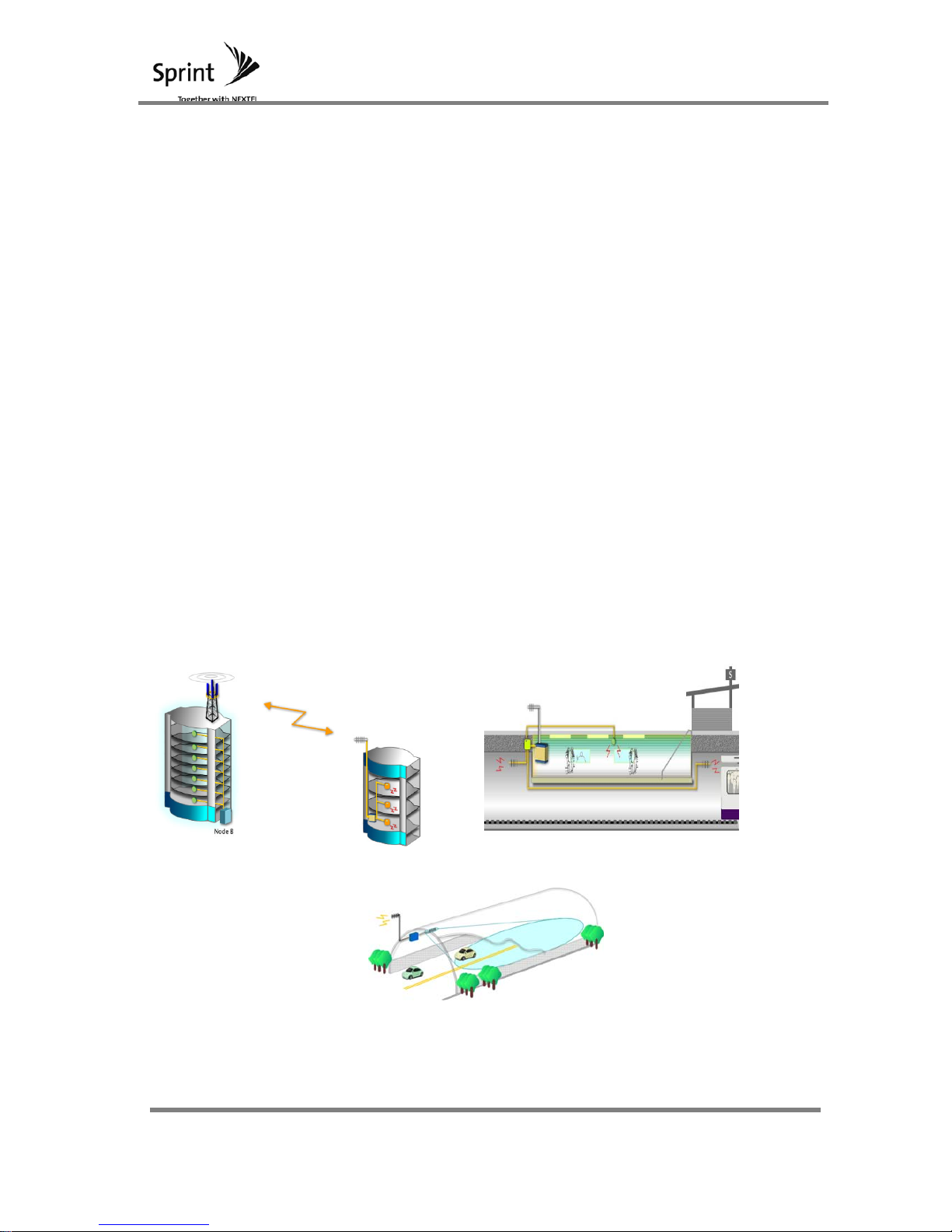
1 System Outline
Mobile WiMAX operates at 2.5GHz frequency band and it offers wireless internet
service at medium to low velocity movement without connection being cutoff.
Mobile WiMAX guarantees mobility and due to inexpensive wireless internet access,
it has become a necessary technology. Generally wireless infrastructures for radio
waves are not serviceable in locations such as in-buildings, islands, mountain
areas and shadow zones. To solve this problem, a repeater system is utilized. This
mobile internet RF repeater system is an OFDMA mobile internet system that allows
services in in-buildings such as offices, underground parking areas, shopping malls,
sub-station locations and small scale areas. This system can provide coverage to
shadow zones where radio waves can’ t penetrate. Some of these locations may
be underground or indoor areas with dense traffic.
<Shadow Zones>
- Underground: subway, underground shopping mall, underground passage,
underground car park, etc.
- Terrestrial: inside large building, tunnel, dense city centers, etc
<In-Building Application> <Subway Application>
<Tunnel Application>
[Figure 1] MOBILE WIMAX System Outline
Page 8

Mobile WiMAX
Manual
8 / 102
2 System Configuration
2.1 Mobile WiMAX
This mobile WiMAX system was developed so that signals could be retransmitted to
shadow zones and thus provide service to these areas. Setup for this unit has become
very common in indoor areas such as underground shadow zones.
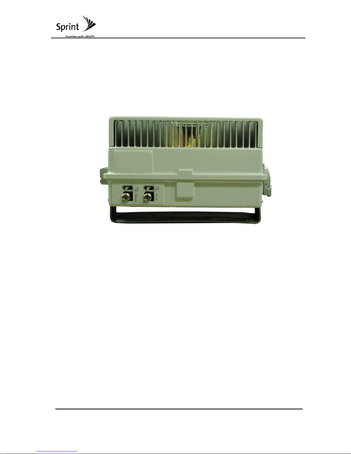
Donor antenna and service antenna ports for the repeaters are configured to N-
females while monitoring ports for repeaters are configured to SMA female.
In order for operator’ s to easily understand the repeaters operational status,
Ethernet port is used so that units can be monitored and allow repairs to be easily
made.
For 33dBm repeater: Maximum value of 33dBm/Total can be emitted for forward
and reverse direction.
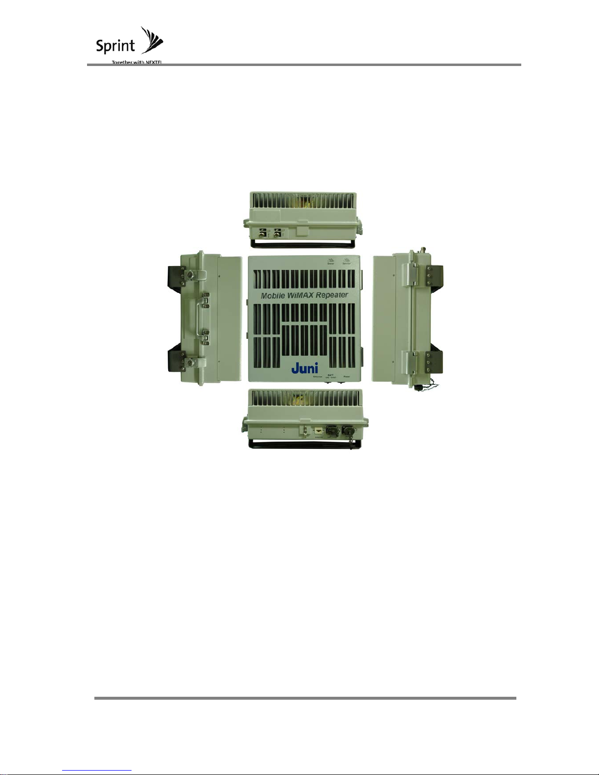
[Figure 2] Frontal view of Mobile WiMAX System
Page 9
Mobile WiMAX
Manual
9 / 102
2.1.1 Base Station Direction (Donor ANT)
Connect the antenna cables to the donor antenna port which is located on the
top section of the repeater. The donor antenna is installed outside on the
building so that it will be able to receive signals from base station.
[Figure 3] Top view of MOBILE WIMAX System
2.1.2 Service Direction (Service ANT)
The service antenna port which is located at the top section of the repeater
is connected to the service antenna cable. These antennas that are
connected to the repeaters are able to provide service to the Shadow Zone
and allow for a satisfactory smooth signal. So, in order to match site
characteristics with an installation location, an antenna type has to be
determined and connected.
2.1.3 UL CPL (Up Link Coupling)
Up link coupling is for operators to analyze the status of an Up Link path. It
is a port for measuring UL signal waveform and strength.
Page 10
Mobile WiMAX
Manual
10 / 102
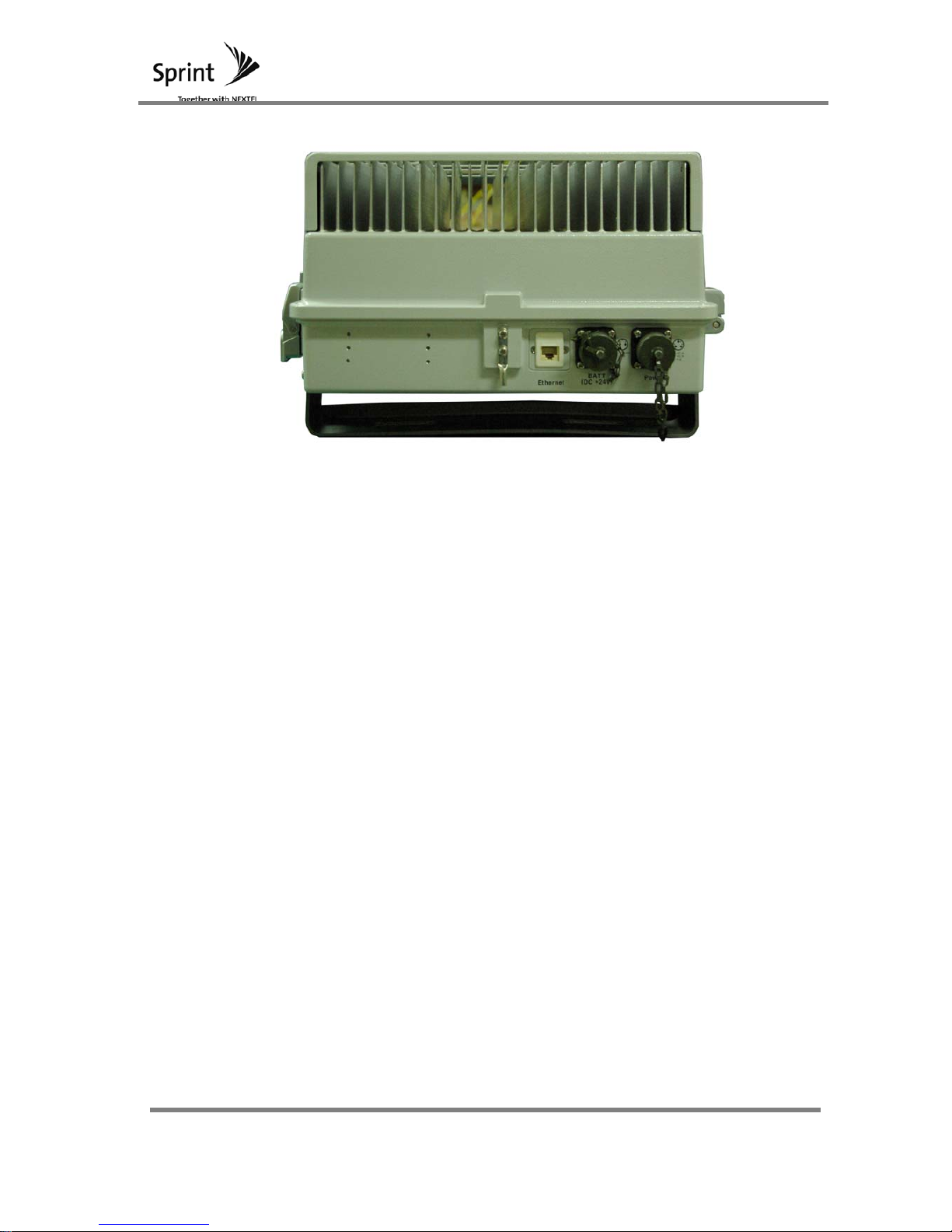
[Figure 4] Bottom view of MOBILE WIMAX System
2.1.4 DL CPL (Down Link Coupling)
Down link coupling is for operators to analyze the status of a Down Link
path. It is a port for measuring DL signal waveform and strength.
2.1.5 GUI
Communication is made between repeaters and the PC operation program
via an RJ-45. The GUI confirms that the conditions of the repeater and
status settings are made on the ports.
2.1.6 AC Power
Repeater’ s operational power supply is connected via an AC cable.
2.1.7 DC Battery
When the AC power supply is cutoff, DC +24V battery is implemented as the
back up power source. (Option)
Page 11

Mobile WiMAX
Manual
11 / 102
3 System Figures and Specifications
3.1 MOBILE WIMAX System Specifications
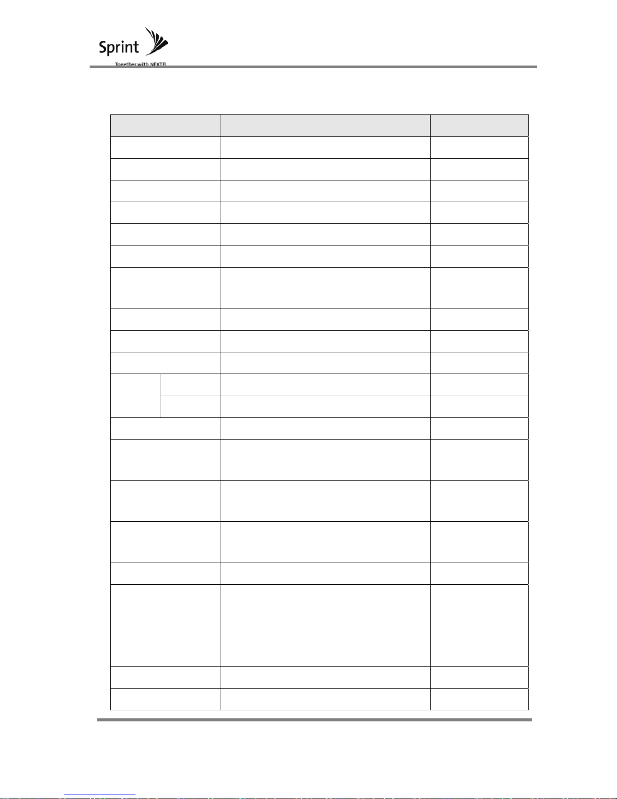
3.1.1 System Figures
Section Features (33dBm Repeater) Notes
Duplexing TDD
Frequency 2,496 ~ 2,690MHz
Output
(Repeaters Final Range)
33dBm/Total (FWD)
33dBm/Total (RVS)
[Table 1] System Figures
3.1.2 Features and Functions
Items
Specifications (33dBm
Repeater)
Notes
RF Connector Type(IN/OUT) N-Type Female
Power Connector Type Waterproof type
Enclosure
Size(W x H x
D)
386mm *334mm *153mm
Mass Less than 25Kg
Structure
Wall Mount Type
Heat Sink Cooling (Natural
Dissipation)
[Table 2] Features and Functions
Page 12

Mobile WiMAX
Manual
12 / 102
3.1.3 Environment Figures
Items Specifications Notes
Operational Temperature
and Humidity Range
-10 ~ +50℃, 5% ~ 95%
Power Consumption Less than 300W
[Table 3] Environment Specification
Page 13

Mobile WiMAX
Manual
13 / 102
3.2 System Specification
3.2.1 System Specification
Section Figures Notes
Frequency 2496 ~ 2690MHz
System delay 5.0usec
For each FA, Maximum
Value
FA delay drift 35 nsec
Frequency Stability ±0.02ppm
Switching time Within 2.5usec Max
Switching time adjustment
range
Within TTG, RTG Section 1usec step
Switching time adjustment
accuracy
Within ± 1us
Pass band Ripple Within ± 1.5dB
System Gain
Down Link 80dB
Up Link 80dB
Gain Control Step Size
0.5dB
Gain Control accuracy Within ± 1dB
Input VSWR Less than 1.4
EVM 3% Source Comparison
Forward input range -50 ~ -20dBm/Total
Noise Figure 5dB
Path isolation More than 120dB Min.
Reverse operating input
range
-50dBm
Pass Band 3dB BW
FA 10MHz Band : Within
11MHz
Each FA
Pass Band 50dB BW
FA 10MHz Band : Within
13MHz
Each FA
Occupied Frequency
Bandwidth
FA 10MHz Band : Within
10MHz
Each FA
Page 14

Mobile WiMAX
Manual
14 / 102
Down Link
Spurious Emission Mask
FA edge±1MHz
More than
Less
than
-40dBc
100KHz
FA
edge±3.5MHz
More than
Less
than
-45dBc
100KHz
Out of Band
Spurious Emission Mask
Under
30MHz~1GHz
Less
than
-13dBm
100KHz
1GHz~12.75GHz
Less
than
-13dBm
1MHz
Up Link
Stop band Rejection
FA edge±1MHz
More than
Less
than
-40dBc
100KHz
FA
edge±3.5MHz
More than
Less
than
-45dBc
100KHz
Reverse Out of Band
Spurious Emission
Under
30MHz~1GHz
Less
than
-13dBm
100KHz
1GHz~12.75GHz
Less
than
-13dBm
1MHz
LED
RF Power
Occurrence of Over Power
Red
VSWR Alarm Occurrence Red
RSSI Alarm Occurrence Red
Over Temp. Alarm Occurrence Red
Undercurrent Alarm Occurrence Red
Page 15

Mobile WiMAX
Manual
15 / 102
Shutdown
DL Input
Level
-14dBm/Total ±2dB
UL Output
Level
35dBm/Total ±2dB
[Table 4] System Specification
Page 16

Mobile WiMAX
Manual
16 / 102
3.3 Main Component Specification
3.3.1 Switch Module Specification
Parameter Specification Remark
Frequency 2496MHz ~ 2690MHz BW=194 MHz
Insertion Loss
1.5dB max.
(Diode 5)
HPA → Service @TTL High
Link → LNA @TTL High
HPA → Link @TTL Low
Service → LNA @TTL Low
VSWR 1.4 max. RF ON Application, All port
Isolation 120 dB min.
HPA → Service @TTL Low
Link → LNA @TTL Low
HPA → Link @TTL High
Service → LNA @TTL High
Switching Time 2.5 ㎲ max. 90% Application.
[Table 5] Switch Module Specification
Page 17
Mobile WiMAX
Manual
17 / 102
3.3.2 UDC (Up/Down Converter) Specification
Parameters Specifications Remark
Frequency1 2518.5MHz BW33MHz
Frequency2 2535MHz BW33MHz
Frequency3 2551.5MHz BW33MHz
Frequency4 2640.5MHz BW33MHz
Frequency5 2657MHz BW33MHz
Frequency6 2673.5MHz BW33MHz
Operational Band
Width
30MHz
System delay 4.7usec
Frequency Stability ±0.02ppm
Passband Ripple Within ± 1 dB -40℃~55℃
System
Gain
Down Link 27dB(@LNA17dB) -40℃~55℃
Up Link 27dB(@LNA17dB) -40℃~55℃
Temp ATT min=8dB(Normal Temperature) @ All path
Rate of Change for
Temperature
±3dB(No temp ATT) -40℃~55℃
Gain Control Step
Size
0.5dB
Gain Control
accuracy
Within 0.7dB
Input VSWR Less than 1.4
EVM 2%
Source
Comparison
(DL64QAM/UL16
QAM)
Tx/Rx input range -17 ~ -47dBm/FA Including LNA
Tx/Rx Output -5dBm
Page 18

Mobile WiMAX
Manual
18 / 102
Noise Figure
5dB
Max (Including
LNA)
12dB
Min (Including
LNA)
OOBE
edge±1.5 ~ 2.5MHz -53dBm/100kHz -40℃~55℃
edge±2.5 ~ 4.5MHz -53dBm/MHz -40℃~55℃
More than
edge±4.5MHz
-82dBm/MHz -40℃~55℃
ALC 30dB
Occupied
Frequency
Bandwidth
Within 30MHz 3FA
Reverse Out of
Band
Spurious Emission
Less than
30MHz~1GHz
Less than
-13dBm
100KHz
1GHz~12GHz
Less than
-13dBm
1MHz
Temperature
For All Conditions
-40℃~55℃
[Table 6] UDC Specification
Page 19

Mobile WiMAX
Manual
19 / 102
3.3.3 BPF Module Specification
3.3.3.1 Electrical Specifications
Donor
Parameters
specifications
Notes
BPF
Frequency Range 2502~2690MHz
Center Frequency 2596MHz
Bandwidth 188MHz
Insertion Loss (Max.) 1.2 dB (Normal Temperature : 1.0 dB)
Return Loss(Min.) 18 dB
Pass Band Ripple (Max.) 0.8 dB
Attenuation(Min.)
2486MHz@20 dBc
2700MHz@30 dBc
Coupling Vale
40±2.0dB(Out Port)
824~894MHz@30dB±2.0dB(In Port)
Operating Temp
-30 ~ +60 ℃
In/ Out Impedance 50 Ω
Page 20

Mobile WiMAX
Manual
20 / 102
Service
Parameters
specifications
Notes
BPF
Frequency Range 2502~2690MHz
Center Frequency 2596MHz
Bandwidth 188MHz
Insertion Loss (Max.) 1.2 dB (Normal Temperature : 1.0 dB)
Return Loss(Min.) 18 dB
Pass Band Ripple (Max.) 0.8 dB
Attenuation(Min.)
2486MHz@20 dBc
2700MHz@30 dBc
Coupling Vale 40±1.5dB(Out Port)
Operating Temp -30 ~ +60 ℃
In/ Out Impedance 50 Ω
[Table 7] BPF Specification
Page 21
Mobile WiMAX
Manual
21 / 102
3.3.4 HPA Specification
Parameters
Specifications for 30dBm Repeater
Remark
Frequency Range 2490~2690MHz
Output Power 36dBm
Gain 40dB ±1dB (min)
Gain Flatness 1.0dB (peak to peak)
Input/Output
VSWR
1.3 :1 (max) to 50Ω
ACP
@ Output Power
OFDM 3FA 36dBm
≤ -20dBm @ Offset
Freq(20MHz), RBW(1MHz)
≤ -20dBm @ Offset
Freq(23MHz), RBW(1MHz)
DC Input Voltage +28V DC
DC Input Current
Typ. 1.2mA, MAX 1.5A (@Vdc= +28V, @OFDM
3FA)
Power Detect
4V@33dBm, (100mV/1dB ),
Detect range : 3dBm ~ 33dBm
Enable (On/Off) Enable : Close /Disable : Open
Over Power Alarm TTL High @ 36dBm
Operating
Temperature
-10 ~ +60℃
Dimension 170 x 140 x 25
RF Connectors SMA Female
Pin Description
(15PinD-SUB
Male)
Pin1, 2, 9, 10 : +28V
Pin3 : HPA Fail Alarm (Shutdown)
Pin4 : Over Temp Alarm (Shutdown)
Pin5 : Over Power Alarm
Pin6 : Over VSWR Alarm
Pin7 : Out Power Det
Pin8 : Enable / Disable
Pin11, 12 : NC
Pin13, 14, 15 : GND
[Table 8] HPA Electrical Specification
Page 22
Mobile WiMAX
Manual
22 / 102
3.3.5 SDM (Sync Detector Module) Specification
3.3.5.1 Electrical Characteristic
Parameter
Specification
Units Remark
min normal max
Input Frequency 2400 2700 MHz
Input Power w/o Damage 0 dBm *Note 1
Normal Input Power -70 -20 dBm *Note 2
Synch Detection Level -70 -20 dBm
Ratio Detection Level -70 -20 dBm
VSWR 2:1
Local Leakage -80 dBm *Note 3
Supply Voltage 4.75 5.5 6 V
Consumption Current 0.3 0.45 1 A 5[V] Range
FA Index Description
0 ~ 775 (Current Frequency) = 2496 MHz + (FA Index * 0.25 MHz)
[Table 9] SDM Electrical Characteristic
3.3.5.2 Environment Specifications
Parameter Specification Remark
Operating Temp. -40~80℃ Humidity 0~90%
Storage Temp.
-40~90℃
-
[Table 10] SDM Environment Specification
3.3.5.3 Mechanical Characteristic
Parameter Specification Remark
Size 110×75×1.6 W×H×D (mm)
Weight TBD
Interface connector 2.54 pitch 2x13
[Table 11] SDM Mechanical Characteristic
Page 23

Mobile WiMAX
Manual
23 / 102
3.3.6 CONTORLLER SPECIFICATION
3.3.6.1 Application Range
Mobile WiMAX repeater’ s control board is applied.
3.3.6.2 Main Characteristic
Items Details
CPU Board Specification
Circuit Version HUEX1101
PCB Version HUEX1101-1
Exterior Size 200mm * 110mm
Thickness, Layer 1.6T, 4 Layer
Main Component
CPU ATmega128 16 MHz
Data Memory
K6X4008C1F-GF70 (4Mbit)
Internal 4kByte EEPROM
Program Memory Internal 1Mbit Flash
Electrical Characteristic
Operation Voltage(Vcc) +7V Æ VCC
Power Stability Element MIC29150-5.0BU
Operational OS uC/OS-II
Temperature Characteristic -30 ~ 80 ℃
[Table 12] Controller Characteristic
3.3.6.3 Mechanical Characteristic
Item Specification
CPU B’ D
FR4 4Layer t=1.6 Size=270mm*240mm
[Table 13] Controller Mechanical Characteristic
Page 24

Mobile WiMAX
Manual
24 / 102
3.3.7 PSU Specification
3.3.7.1 GENERAL CHARACTERISTIC
Items Specification
Input
Input Voltage and
Range
110 ~ 124 or 208 ~ 240VAC (Switch Selection)
Frequency 55 ~ 65Hz
Constant Single Phase
Output
Rated Voltage and
Load Current
+27VDC/5A, +5.5VDC/1.5A,
+7VDC/4A,-27VDC/0.1A
Voltage Fluctuation
Limit
Rated Output Voltage ± Within 2% (Line/Load
Regulation)
Ripple/Spike
Ripple, Spike inclusion, Output Voltage less
than 1% of 10V which is within 100mV
Excess Voltage
(Sudden Load
Change)
Peak Value Less than 1V
Recovery
Time
Less than 35msec
Efficiency More than 75%
Hold-up Time Maintain more than 20msec
Over Voltage
Protection
Output level of 110 ~140% Shutdown Protection
Over Current
Protection
Maximum output current is between 110~140%
for current limit. Auto return Sub-power for over
current protection follows the elements
characteristic.
Arrival Time Rating
For voltage rating, the arrival time is within 100
msecond. OVER&UNDER SHOOT voltage rating
is within 90 ~ 110%
Time Drift
After 30 minutes of operation, when output
voltage is measured, value should be within ±
0.25%
Page 25
Mobile WiMAX
Manual
25 / 102
Over-Heating
Protection
When PSU’ s Base Plate exceeds 100 oC,
system shuts down
BATT. Terminal
Voltage
+21V ±0.5V
[Table 14] Power Source Specification
3.3.7.2 Output Characteristic
Rated Output Io
Ripple & Noise
Vo Tolerance Min Max
+27V ±2% 0.1A 4A 2000mV
+5.5V ±2% 0.1A 1.5A 100mV
+7V ±2% 0.1A 4A 120mV
-27V ±2% 0.01A 0.1A 200mV
[Table 15] Power Source Output Characteristic
3.3.7.3 Environment Characteristic
Specification Items Specification Remarks
Operating Temperature and
Humidity
-30°C/10%~70°C/90%
Storage Temperature and
Humidity
-30°C/10%~70°C/90%
Output Voltage Change 0.05%/°C
Cooling Mode Conduction Cooling Mode
High Temperature Test
Condition (Full load)
For 72 hours at 70°C
Page 26

Mobile WiMAX
Manual
26 / 102
COLD START
Storing the unit at -30°C for 10
hours and then turning it on
[Table 16] Power Source Environment Characteristic
Page 27
Mobile WiMAX
Manual
27 / 102
4 System Structure and Function
4.1 Repeater Structure and Explanation
4.1.1 Repeater External Appearance
Repeater’ s enclosure prevents dust and other pollutant particles from entering and is
designed for wall mount positioning. Heat-sink is placed to dissipate heat.
[Figure 5] Mobile WiMAX RF Repeater Structure
Page 28
Mobile WiMAX
Manual
28 / 102
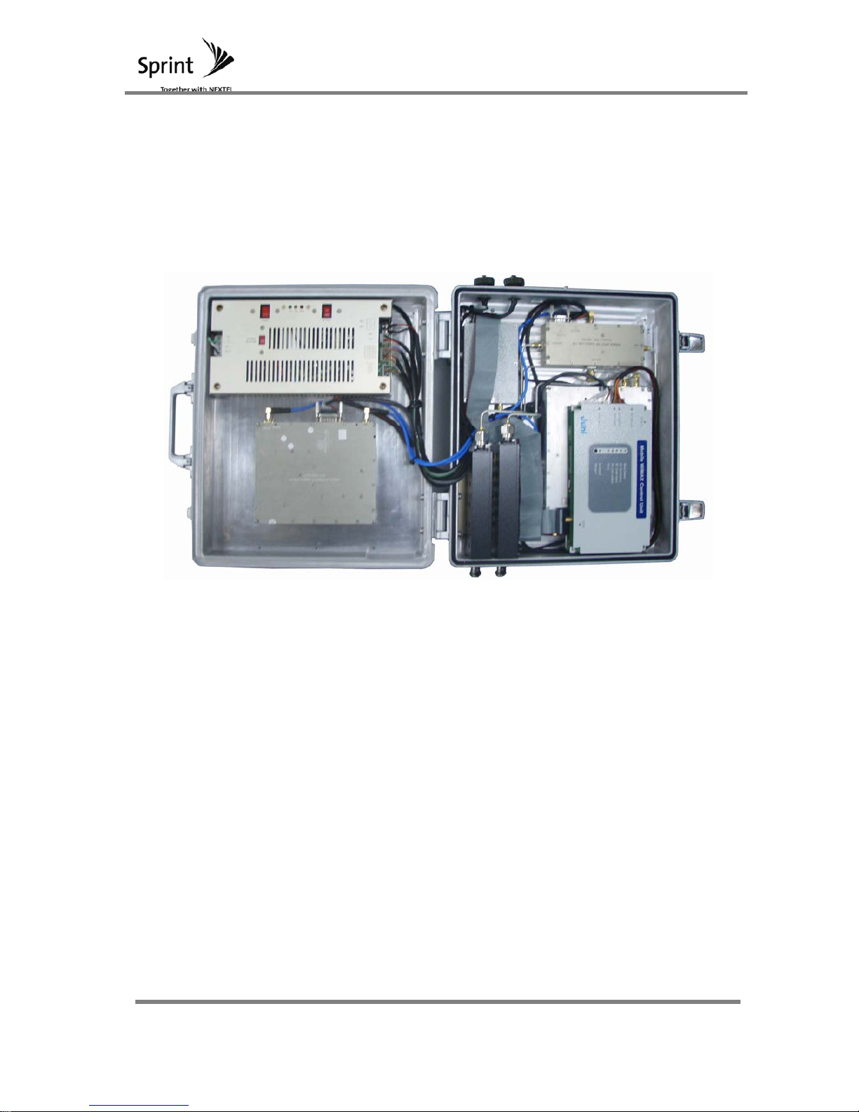
4.1.2 REPEATER INTERIOR
Structure of the unit is simplified so that maintenance will be easily handled; therefore
the number of modules is minimized. Inside the repeater enclosure, there are 6 modules
that are laid out. These modules are Switch, PSU, HPA, BPF, UDC and Controller.
[Figure 6] Mobile WiMAX Repeater’ s Interior
Page 29
Mobile WiMAX
Manual
29 / 102
4.2 Explanation of Internal Configuration
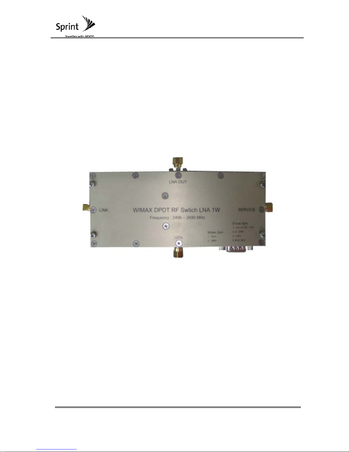
4.2.1 Switch Module
WIMAX DPDT (Double Pole Double Throw) RF Switch LNA is applied to the
WIMAX RF repeater.
High Isolation values are used for Down Link and Up Link segregation (More
than 120dB). With low insertion loss, Noise Figure value and HPA output loss
can be lowered. When TTL sync is high, downlink path is set and when TTL
sync is low, Up Link path is set.
[Figure 7] Switch Module Feature
4.2.1.1 HPA
HPA is the input signal port for RF signals which travel out the Link and Service port.
4.2.1.2 LNA
Signals make their way into Link and Service ports, whereby weak signals are amplifie
d and exit out of LNA OUT. Signals are then delivered to up/down converter’ s input
port.
4.2.1.3 Service
Service port connects directly to BPF. Based on a switching mechanism, high
Page 30

Mobile WiMAX
Manual
30 / 102
amplified signals enter into the HPA and exit its way out of the service port. The signal
then gets filtered by BPF and travels toward the service antenna. When the switch
module is in a different state, weak signals from the service antenna pass through the
BPF and into the service port. These signals exit the LNA out port to be amplified.
4.2.1.4 Link
The Link port connects directly to BPF. Based on a switching mechanism, high amplifi
ed signals enter into the HPA and exit its way out of the Link port. The signal then get
s filtered by BPF and travels toward the donor antenna. When the switch module is in
a different state, weak signals from the donor antenna pass through the BPF and into
the Link port. These signals exit the LNA out port to be amplified.
Page 31

Mobile WiMAX
Manual
31 / 102
4.2.2 UDC Module
4.2.2.1 RF Module
Mobile WiMAX signal is received at the LNA (Switch Module). The signal is down
converted and passed through a SAW filter. Once any unwanted signals have been
removed, it is up converted, amplified and then sent to the HPA (Switch module).
Digital variable attenuators are built into the repeater so full gain control can be performed
for forward and reverse direction (As it handles duplex transmission).
[Figure 8] UDC Module Feature
Page 32

Mobile WiMAX
Manual
32 / 102
4.2.3 BPF Module
These modules receive Mobile WiMAX signals from antennas outside. Only BRS-
Band’ s are passed and signals are delivered to the switch module. These
modules also receive output signals from the switch module of the HPA port and
forward them to the antennas.
[Figure 9] BPF Module Feature
Page 33

Mobile WiMAX
Manual
33 / 102
4.2.4 HPA MODULE
HPA module receives filtered and amplified mobile WiMAX signals from UDC module.
These signals are then amplified to serviceable capacity and sent to the switch module.
[Figure 10] HPA Module Feature
Page 34

Mobile WiMAX
Manual
34 / 102
4.2.5 SDM
TDD switching signal and repeater oscillation sensing functions are provided. In
order to allow for TDD switching signal, synchronization detection and rate
detection functions are set up. Also, oscillation sensing function is built in.
[Figure 11] SDM Feature
Characteristics of the functions that were implemented above are shown below.
Sync Detection
Cell search
Function: Searches for 114 Mobile WiMAX preambles and to detect Mobile WiMAX signals.
Preamble Detection
Function: For Cell search, tracking quality from detected preambles.
FA search
When cell search is unsuccessful in searching for a designated FA, FA is changed and
cell search is executed again.
TDD Switch
Page 35

Mobile WiMAX
Manual
35 / 102
Generation of 8 switching signal function
Rate Detection
FFT
Mobile WiMAX use, 1024 FFT function
Channel Estimation/Compensation
Reconstruction of Fading signal function
Frequency Offset Estimation/Compensation
AWR providing BB signals for RF frequency offset compensation function
Forward Error Correction
Convolution Code Decoder
Convolution Turbo Code Decoder
Minute Oscillation
Feedback Path detection
Additional Function
AGC
In order to improve AWR performance, AGC is provided for AWR’ s input signal.
RSSI
Providing Preamble’ s RSSI
Page 36

Mobile WiMAX
Manual
36 / 102
4.2.6 Controller Module
Main NMS board includes the Mobile WiMAX repeater’ s CPU. For each sector, monitoring
and control functions are performed.
4.2.6.1 Block Diagram
[Figure 12] Controller Block Diagram
4.2.6.2 CPU(Atmel ATmega128)
AVR mega series One-chip type CPU
Operating Frequency: 16 MHz
1Mbit Program Memory (Flash) built in
4kByte internal SRAM and 4kByte EEPROM built in for data back up use
2 Serial Port (UART) built in
4.2.6.3 PC and Communication Function
By utilizing PC’ s application programs, repeaters can monitor and control
activities at the controller. PC will require a connection of 38400bps on a RJ-45
cable for communication.
4.2.6.4 Digital Module and Communication Function
Digital Module’ s status of monitoring and control can be performed.
4.2.6.5 Data Back Up Function
At the PC and notebook’ s key, controlled values are saved in the controller.
Therefore when the repeater is powered off or reset, these set values will be
maintained.
Page 37

Mobile WiMAX
Manual
37 / 102
4.2.6.6 Attn Control Function
ATTN can be controlled.
All Attn setting ranges are 0~30 dB.
4.2.6.7 Power/Temperature Detect Function
For each module, analog inputs of power and temperature are converted to
digital output. It is displayed in the PC and set values are executed for
characteristic functions.
4.2.6.8 Alarm Check Function
For each module, output of all status information are collected and displayed in
the PC. Afterwards, relevant functions can be performed.
Page 38

Mobile WiMAX
Manual
38 / 102
4.2.7 PSU
In order to provide stable DC power from an AC power input, this power supply unit is
utilized. AC 110 ~ 125 / 208 ~ 240Vac input (Switch is used) power is received and
converted to SMPS (Switch Mode Power Supply) of +27V, +7V, +5.5V, -27V outputs.
[Figure 13] PSU Feature
Main power supply unit’ s cooling method is by conduction cooling. The unit has been
designed to meet all safety standards for dielectric structure; including dielectric potential
and dielectric resistance characteristics. The power supply unit has been designed with a
PWM switching for high efficiency and the switching frequency operates at 67 KHz ± 10
KHz. For all electrical characteristic testing, rated input, output conditions and
components should be connected.
Page 39

Mobile WiMAX
Manual
39 / 102
5 Signal Block Diagram and Signal Flow
5.1 System Block Diagram
In order to minimize the size of the device, we have implemented a design that is
single pass and bi-directional serviceability.
A single pass repeater is small, simple and reduces the cost of the system. It
also generates less heat and is light weight thus installation and maintenance
becomes easy to handle. Single pass, bi-directional repeater’ s block diagram is
shown below along with other components that have been implemented such BPF
, RF Switch (DPDT), LNA, Converter and HPA Module.
[Figure 14] MOBILE WIMAX Repeater Block
5.1.1 Forward Direction Block Explanation
Signals from BTS are received via the repeater’ s donor antenna. These signals are then
filtered through the BPF (Band Pass Filter) and enter into the DPDT RF switch as inputs.
Page 40

Mobile WiMAX
Manual
40 / 102
Within the DPDT switch, down link and up link paths are switched alternately. In a down
link switching state, signals are sent to LNA where low noise amplifications are applied
and sent to the Up/Down Converter. At the converter, only the relevant bands are passed t
hrough the SAW filter and forwarded to the HPA. HPA amplifies these signals to high outp
ut and passes it through to the DPDT switch and BPF. The signals finally radiate out the s
ervice antenna.
5.1.2 Reverse Direction Block Explanation
Signals from PSS (Portable Subscriber Station) are received via repeater’ s service antenn
a. These signals are then filtered through the BPF (Band Pass Filter) and enter into the DP
DT RF switch as inputs. Within the DPDT switch, down link and up link paths are switched
alternately. In an up link switching state, signals are sent to LNA where low noise amplifica
tions are applied and sent to the Up/Down Converter. At the converter, only the relevant b
ands are passed through the SAW filter and forwarded to HPA. HPA amplifies these signal
s to high output and passes it through to the DPDT switch and BPF. The signals finally rad
iate out the donor antenna.
5.2 UNIT MODULE BLOCK DIAGRAM
5.2.1 SWITCH MODULE BLOCK DIAGRAM
5.2.1.1 Like the figure below, switch module implements RF Switch (DPD
T) and LNA into one module.
5.2.1.2 For Mobile WiMAX and TDD based systems, at a set given time,
system will have to operate at one path and change moments later.
Due to this characteristic for up link and down link signals, this
module was developed specifically for this type of operation.
Page 41

Mobile WiMAX
Manual
41 / 102
[Figure 15] Switch Module Block
Page 42

Mobile WiMAX
Manual
42 / 102
5.2.2 UDC BLOCK DIAGRAM
5.2.2.1 RF MODULE
Like the figure below, the UDC (Up/Down Converter) module is configured to all
of the repeater’ s functions such as gain control from attenuators, up and down
conversion of frequency from PLL and mixer, filters that remove unwanted bands
and amplified signals from amplifiers. UDC manages the role of filtering and
amplifying received signals via LNA. Signals are sufficiently amplified by HPA so
that it can be emitted out towards the BTS or PSS.
RF-OUT
Power Det.
RF-IN
AT1
AMP
AMP
AT2
140M
AMP
AT3
AMP
PLL
ABCD
140M
AMP
AMP
AMP AMP
AMP
AMP
140M
AMPAMP
AMP
AMP
AMP
AMP
140M
PLL
EFGH
[Figure 16] UDC Block
Page 43

Mobile WiMAX
Manual
43 / 102
5.2.3 SDM & CTRL BLOCK DIAGRAM
From the BTS, SDM (Sync. Detector Module) & CTRL (Control) modules receives
signals and extracts TTG and RTG. Signals that control the DPDT switching is sent as
IHS and system determines the direction of operation. Repeater determines the
operation status and control features are performed in order for it to function smoothly.
Via the GUI, status of the repeater can be determined on the PC. The repeater’ s
status can also be sent via host’ s NMS.
Base Band
ConvertingBlock
(RB)
CB
I/F
ADC FPGA
Memory
CPU
RF IN
System
[Figure 17] SDM Block
Page 44

Mobile WiMAX
Manual
44 / 102
5.2.4 PSU BLOCK DIAGRAM
Repeaters running power for the power supply unit is AC 110 ~ 125 / 208 ~ 240Vac input
(Switch used). Power is converted to DC and supplied to each component.
[Figure 18] PSU Block
Page 45

Mobile WiMAX
Manual
45 / 102
6 Additional Function
6.1 ASD (AUTO SHUTDOWN) Function
6.1.1 Aim of ASD Functions
In order to protect the repeaters setup and networks stability, output must be
suppressed. This is done by activating the automatic shutdown function when
down link input is high, up link output is high or when oscillation occurs.
Shutdown function operates by following the algorithms shown in the figure below.
6.1.2 ASD Management Procedure
For Automatic Shutdown, when DL Input is high, value is shown as -14dBm/Total
and when UL Output is high, +36dBm/3FA is the value. ASD algorithm is
performed like the figure below.
Section Specification Remark
Detection
Level
Down Link Input -14dBm/Total
Up Link Output 36dBm/Total
[Table 17] ASD Function Operation Condition
[Figure 19] DL Over Input and UL Over Output Shutdown Algorithm
If the above oscillations recheck process confirms that there are no oscillations, then all
Page 46

Mobile WiMAX
Manual
46 / 102
records of previous steps are deleted and normal servicing is initiated. However, if
oscillation is detected, oscillation check step starts from the beginning and recommences
oscillation re-check process.
Page 47

Mobile WiMAX
Manual
47 / 102
6.2 ALC Function
6.2.1 AIM of ALC FUNCTION
6.2.1.1 In order to protect DL’ s over input, ALC (Automatic Level
Control) function is implemented. ALC’ s operational range input
signal and DL’ s normal input range is -47dBm/Total ~ -
17dBm/Total.
6.2.2 Management Procedure
6.2.2.1 ALC’ s maximum set point is -17dBm/Total and its minimum set
point is -47dBm/Total. When a signal coming into the system is
higher than ALC’ s set point, the repeater’ s ASD function is
initiated.
Section
Specification Remarks
ALC Set Level -47dBm/Total~ -17dBm/Total
ASD Operation Level ALC Set Level +3dBm
[Table 18] Function and Operation Level
Page 48

Mobile WiMAX
Manual
48 / 102
PC Application Program
Page 49

Mobile WiMAX
Manual
49 / 102
1 PC Application Program
The icons and folder names displayed in the manual can differ with that of the User’ s PC.
1.1 Program Installation
When accessing the installation program, the following files will be present.
<Figure 1-1>
Double click the Setup.exe file to begin installation.
A window screen similar to one shown below will appear. The user is able to cancel and
exit the installation process by clicking the [Cancel] button or continue with the
installation by clicking the [Next] button.
Page 50

Mobile WiMAX
Manual
50 / 102
<Figure 1-2> Install Start
The user must select the folder in which the program will be saved under.
The standard folder in which the software is saved under is C:₩Program Files₩Wi-Max.
However, if the user decides to customize the location of the program, it can be done by
clicking the [Browse] button.
<Figure 1-3> Installation Folder Selection
Click the [Next] button once the destination has been selected.
This will prompt a new window indicating installation process is ready.
Page 51

Mobile WiMAX
Manual
51 / 102
<Figure 1-4> Ready to Install Window
The [Back] button will allow the user to re-enter the section where he or she selects the
destination of the software. If the user decides to continue with the installation process,
this can be done by clicking the [Next] button. During the installation process, a window
screen like the one shown in Figure 1-5 will automatically appear indicating the status of
the installation.
Once the program has been completely installed, a window screen like the one shown in
Figure 1-6 will automatically appear indicating the installation has been successfully
completed.
The user can exit the Installation Wizard by clicking the [Finish] button.
Page 52

Mobile WiMAX
Manual
52 / 102
<Figure1-5> Installation Status Window
<Figure 1-6> Successful Installation Window
1.2
Program Start
Once the program has been successfully installed, the user may access the program by
Page 53

Mobile WiMAX
Manual
53 / 102
clicking the [Start] ->Program->WiMAX button at the bottom right corner of the main
window screen
<Figure 2-1> Program Start
1.3 Status Monitoring and Control
Connect the serial port to the PC and open the software. The baud rate should be set at
38400bps. If the user wants to change the com port, it can be done by first pressing the
[Port Close], then changing it to the desired port and then clicking the [Port Open]
button. The connection can be verified by checking the TXD / RXD LED on the left of the
screen. A blinking TXD / RXD LED indicate a successful connection.
1.3.1 Status Monitoring
The PC will automatically update the system values every 1 second.
Page 54

Mobile WiMAX
Manual
54 / 102
<Figure 3-1> Status Monitoring Window
The function of each button is explained below
Port Open / Close Opening and closing current set port
Debug Accessing the communication information Window
SDM Accessing SDM Window
Table Accessing the Table Window
Download Accessing the Download Window
Exit Exiting the Program
Reset System Reboot
Set Change settings
Page 55

Mobile WiMAX
Manual
55 / 102
1.3.2 .Status Control and Setting
When changing the setting of the system through the software, the text of the changed ite
ms will change to a blue color. By pressing the [Set] button, all values that correspond to
an item with blue text will be modified.
<Figure 3-2> Status Control and Setting Window
Page 56

Mobile WiMAX
Manual
56 / 102
1.3.3 Status Monitoring and Control Items
The following table lists the various items of the repeater system that can be monitored
and changed.
Item Monitoring/Control Notes
Repeater Info.
Maker Monitoring
Type Monitoring/Control
Version Monitoring
Temp Monitoring [‘ C]
DETECT
Current Monitoring [A]
Under Current Monitoring/Control [A]
Det 27V Monitoring [V]
Input Power Monitoring [dBm]
RSSI Monitoring/Control
Alarm: Red, Normal: Green
[dBm]
LPA
LPA Enable Monitoring/Control ON / OFF
LPA Power Monitoring [dBm]
LPA Power Limit Monitoring/Control [dBm]
LPA Temp Monitoring [‘ C]
PLL
Enable A Monitoring/Control ON / OFF
Enable B Monitoring/Control ON / OFF
Band Selection Monitoring/Control [MHz]
AGC
AGC ON/OFF Monitoring/Control ON / OFF
AGC Limit Monitoring/Control
ATT
Down Link Monitoring/Control [dB]
Up Link Monitoring/Control [dB]
ALARM
PSU Monitoring Alarm: Red, Normal: Green
Battery Monitoring Alarm: Red, Normal: Green
VSWR Monitoring Alarm: Red, Normal: Green
Page 57

Mobile WiMAX
Manual
57 / 102
Unlock Monitoring Alarm: Red, Normal: Green
Out of Sync Monitoring Alarm: Red, Normal: Green
Oscillation Monitoring Alarm: Red, Normal: Green
Door Monitoring Alarm: Red, Normal: Green
Ocer
Temperature
Monitoring Alarm: Red, Normal: Green
RF Power Monitoring Alarm: Red, Normal: Green
1.3.4 SDM Status Monitoring
By clicking the [SDM] button on the Status/Control window, the user can access the SDM
Data Monitoring window.
The PC will automatically update the system values every 1 second.
Page 58

Mobile WiMAX
Manual
58 / 102
<Figure 3-3> SDM Status Monitoring and Control Window
Page 59

Mobile WiMAX
Manual
59 / 102
1.3.5 SDM Control Settings
When changing the settings of the system through the software, the text of the changed it
ems will change to a blue color. By pressing the [Set] button, all values that correspond t
o an item with a blue text will be modified.
<Figure 3-4> SDM Status Control Window
Page 60

Mobile WiMAX
Manual
60 / 102
1.3.6 SDM Status Monitoring and Control Items
The following table lists the various SDM status items that can be monitored and changed.
Item Monitoring/Control Notes
Reset Monitoring/Control
Auto Ratio Enable Monitoring/Control Enable / Disable
DL Ratio Selection Monitoring/Control
Detect Ratio Monitoring
Detected Preamble Index Monitoring/Control Enable / Disable
Sync Status Monitoring
FA Index 1 Monitoring/Control [MHz]
FA Index 2 Monitoring/Control [MHz]
FA Index 3 Monitoring/Control [MHz]
FA Index 4 Monitoring/Control [MHz]
FA Index 5 Monitoring/Control [MHz]
FA Index 6 Monitoring/Control [MHz]
FA Search Monitoring/Control Number / Stage Limit
CINR Monitoring
Preamble Power Monitoring [dBm]
AGC Value Monitoring
FO Alarm Enable Monitoring/Control Enable / Disable
System Delay Monitoring/Control
Cell Search Enable Monitoring/Control Enable / Disable
Preamble Index Monitoring/Control
FO Threshold Monitoring/Control
FO Quantity Monitoring
S/W Ver. Monitoring/Control
H/W Ver. Monitoring/Control
Page 61

Mobile WiMAX
Manual
61 / 102
RSSI Monitoring
PLL Setting Monitoring/Control
Bandwidth Selection Monitoring/Control
Service Band Monitoring/Control
Start Offset
TDD Switch0 (TX) Monitoring/Control
TDD Switch1 (RX) Monitoring/Control
TDD Switch2 (SW) Monitoring/Control
TDD Switch3
(CTRL)
Monitoring/Control
TDD Switch4 Monitoring/Control
TDD Switch5 Monitoring/Control
TDD Switch6 Monitoring/Control
TDD Switch7 Monitoring/Control
End Offset
TDD Switch0 (TX) Monitoring/Control
TDD Switch1 (RX) Monitoring/Control
TDD Switch2 (SW) Monitoring/Control
TDD Switch3
(CTRL)
Monitoring/Control
TDD Switch4 Monitoring/Control
TDD Switch5 Monitoring/Control
TDD Switch6 Monitoring/Control
TDD Switch7 Monitoring/Control
TDD Switch
TDD Switch0 (TX) Monitoring/Control
TDD Switch1 (RX) Monitoring/Control
TDD Switch2 (SW) Monitoring/Control
TDD Switch3
(CTRL)
Monitoring/Control
TDD Switch4 Monitoring/Control
TDD Switch5 Monitoring/Control
TDD Switch6 Monitoring/Control
Page 62

Mobile WiMAX
Manual
62 / 102
TDD Switch7 Monitoring/Control
TDD Switch
Default
TDD Switch0 (TX) Monitoring/Control
TDD Switch1 (RX) Monitoring/Control
TDD Switch2 (SW) Monitoring/Control
TDD Switch3
(CTRL)
Monitoring/Control
TDD Switch4 Monitoring/Control
TDD Switch5 Monitoring/Control
TDD Switch6 Monitoring/Control
TDD Switch7 Monitoring/Control
TDD Switch
Polarity
TDD Switch0 (TX) Monitoring/Control
TDD Switch1 (RX) Monitoring/Control
TDD Switch2 (SW) Monitoring/Control
TDD Switch3
(CTRL)
Monitoring/Control
TDD Switch4 Monitoring/Control
TDD Switch5 Monitoring/Control
TDD Switch6 Monitoring/Control
TDD Switch7 Monitoring/Control
Mux TDD Switch
& Out-Of Sync
TDD Switch0 (TX) Monitoring/Control
TDD Switch1 (RX) Monitoring/Control
TDD Switch2 (SW) Monitoring/Control
TDD Switch3
(CTRL)
Monitoring/Control
TDD Switch4 Monitoring/Control
TDD Switch5 Monitoring/Control
TDD Switch6 Monitoring/Control
TDD Switch7 Monitoring/Control
Page 63

Mobile WiMAX
Manual
63 / 102
1.3.7 Hidden Status Control Settings
The user is able to access the Hidden Data Status Control and Settings section by
pressing the [F8] key when he/she enters the Status Control and Settings window.
Automatic polling will occur every 1 sec between the system and the PC as the status
values are displayed.
<Figure 3-5> Hidden Status Control Window
1.3.8 Hidden Status Setup
When changing the setting of the system through the software, the text of the changed ite
ms will change to a blue color. By pressing the [Set] button, all values that correspond to
an item with a blue text will be modified.
Page 64

Mobile WiMAX
Manual
64 / 102
<Figure 3-6> Hidden Status Control Window
1.3.9 Hidden Status Monitoring/Control Items
The following table lists the various Hidden status items that can be monitored and
changed.
Item Monitoring/Control Notes
Sync Shutdown Monitoring/Control ON / OFF
Temp Comp. Monitoring/Control ON / OFF
Det Mode Monitoring/Control Auto / Manual
Path Mode Monitoring/Control Down Link / Up Link
Down Link ATT Offset
Monitoring/Control [dB]
Monitoring/Control [dB]
Monitoring/Control [dB]
Up Link ATT Offset
Monitoring/Control [dB]
Monitoring/Control [dB]
Monitoring/Control [dB]
Page 65

Mobile WiMAX
Manual
65 / 102
1.4 Table
By clicking the [Table] button on the Status Monitoring/Control window, the user is able t
o access the System Detect Table as shown below. The user is able to monitor and contr
ol these values.
<Figure 4-1> LPA Power Table
3.1.4.1 Table Selection
The user is able to access the table for the following items:
LPA Power
LPA Temp
Input Detect
Current Monitor
Det 27V Monitor
Page 66

Mobile WiMAX
Manual
66 / 102
ATTN 0
ATTN 1
ATTN 2
DL Temp ATTN
UL Temp ATTN
The user is able to access the table of the different items by using the combination box
and selecting the desired item.
<Figure 4-2> Table Selection
1.4.1 Table Value Input
The user is able to change the data value by using the cursor provided or by registering a
new value.
<Figure 4-3> Table Value Input
When the voltage value is changed by the user as shown above, the AD value will
automatically change accordingly.
The user may change several values within a range simultaneously by using the
[Spreading] function. As shown in the figures below, first check the box with the
Page 67

Mobile WiMAX
Manual
67 / 102
beginning and end range values. Once this has been done, press the [Spreading] button.
This will automatically set values for all within that range as shown in figure 4-5
<Figure 4-4> First Phase of Spreading
Page 68

Mobile WiMAX
Manual
68 / 102
<Figure 4-5> Spreading Result
When entering the Detect Table, the current voltage reading is displayed on the left corner
. This value can be automatically applied to the value boxes by right clicking the box wher
e the user is able to change the values.
<Figure 4-6> Current Voltage Reading
The Offset value located at the bottom left corner can be adjusted by the user. NOTE*
The Offset Value will apply to all values in the table.
<Figure 4-7> Table Offset
Page 69

Mobile WiMAX
Manual
69 / 102
1.4.2 Table Attribute Setting
The Offset Value located at the bottom left corner can be adjusted by the user. NOTE*
The Offset Value will apply to all values in the table.
<Figure 4-8> Table Attribute
Explanations of other function buttons are listed below.
Save Saving the currently updated values into the PC.
Load Loading an already saved set range of values.
Set To apply the changes made by the user.
Exit Exiting the table
Page 70

Mobile WiMAX
Manual
70 / 102
1.5 DOWNLOAD
1.5.1 Download Preparation
By clicking the Download button on the Status/Monitoring screen, the user is able to F/W
Download files into the system. By clicking the Download button the user will be directed
to a download window as seen below.
<Figure 5-1> Download Ready Window
Here, [File Open] button is clicked.
If user wants to exit, click the [Exit] button.
Page 71

Mobile WiMAX
Manual
71 / 102
1.5.2 File Open
Click the [File Open] button to access the file search window shown below.
<Figure 5-2> File Open
The user has the option of typing the exact file name in the entry box or clicking and
selecting the “ .bin” file from the main screen. Once the user selects the file and clicks
the [OK] button, the window will indicate the file name; file size and total frame of the
selected file.
Page 72

Mobile WiMAX
Manual
72 / 102
<Figure 5-3> Preparation for Download
1.5.3 Download Start
Once the user presses the [Start] button as shown in the figure <Figure 5-3> above, the
download process will begin. This will be followed by a progress bar indicating the status
of download as shown below.
<Figure 5-4> Download Progress Window
If the user presses the [Cancel] button, the download will immediately terminate.
If the download process is not successfully completed, a window notifying a failure will
appear.
Page 73

Mobile WiMAX
Manual
73 / 102
<Figure 5-5> Window Notifying a Failed Download Attempt
1.5.4 Download Complete
Once download the is complete, a flashing screen will appear during the initialization perio
d. Completion is notified to the user by a window indicating that download has been com
pleted.
Page 74

Mobile WiMAX
Manual
74 / 102
[Figure 5-6] Flash Write
Once all downloading has been completed, a small confirmation will pop up as shown bel
ow.
[Figure 5-7] Download Complete
Page 75

Mobile WiMAX
Manual
75 / 102
2 WEB GUI
2.1 Program Start
2.1.1 Web Site Link
Open an Internet Explorer window or an available web browser. Enter an appropriate IP
and port address in the URL column.
If the correct link has been entered, a Login display like the one below will be shown.
<Figure 10-1> Initial Login Page
2.1.2 Login
After a specified User ID and relevant account password has been entered, click on the
[Login] button.
Page 76

Mobile WiMAX
Manual
76 / 102
<Figure 10-2> Login
Page 77

Mobile WiMAX
Manual
77 / 102
2.2 Basic Display Configuration
2.2.1 Initial Display
After Login has been successful, a display like the one below is shown. Initial display will
be a ‘ Control’ display.
<Figure 10-3> Initial Display
Page 78

Mobile WiMAX
Manual
78 / 102
2.2.2 Menu
Near the top of the web page, there are some menu items. When clicked, it will display
the relevant function web page.
<Figure 10-4> Menu
Below are the menu functions and explanations:
- Security : Account Password Change.
- Clock : System Clock change.
- Network : Network and miscellaneous information setting.
- Control : System status monitoring and control.
- Hidden : System hidden items status monitoring and control.
- SYNC : SYNC system status monitoring and control.
- Upload : Repeater firmware Update.
- Reboot : System Reboot.
- Alarm History : Monitoring occurrence of alarm at present conditions.
- Alarm Mask : Alarm mask status monitoring and control.
- Logout : Logout for current user and returning to login display page.
Page 79

Mobile WiMAX
Manual
79 / 102
2.2.3 Date/Time Information
On the top left section of the web page, below the main menu items, the system’ s set
clock is displayed.
<Figure 10-5> Date/Time Information
2.2.4 Network/System Information
Below the Date/Time Information section, System and Network Information are displayed.
<Figure 10-6> Network/System Information
Page 80

Mobile WiMAX
Manual
80 / 102
2.3 Security (Password Setup)
Security is used for changing a user’ s Password. All Passwords must be set with 4~8
characters.
When changing a user’ s Password, the user account must be selected. Also, once
Current Password, New Password and Retyping of the New Password has been inserted,
[APPLY] button is clicked.
<Figure 10-7> Security (Password Setup)
Page 81

Mobile WiMAX
Manual
81 / 102
2.4 Clock
Clock menu displays and sets system’ s time. The changed clock values can be viewed
on the ‘ RTC Time’ section located below ‘ Juni’ logo left of the page. When
changing Date/Time, the desired inputs are added and [Set Date/Time] button is clicked.
<Figure 10-8> Clock
Page 82

Mobile WiMAX
Manual
82 / 102
2.5 Network
Network menu monitors and controls network information. When there are items in the
network setup that needs to be changed, information is added and changed in the
‘ Network Setup’ section. After all relevant information has been added, [SETUP] button
which is located at the top and bottom of the page, is clicked.
<Figure 10-9> Network
Page 83

Mobile WiMAX
Manual
83 / 102
<Figure 10-10> Network Setup
Page 84

Mobile WiMAX
Manual
84 / 102
Following shows items that can be monitored or controlled in the Network Setup page:
Item Notes
Cascade Code
Location Information
Latitude
Longitude
Heartbeat Interval [minutes]
Part Number
Vendor Serial Number
Sprint Asset Tag
Sprint Serial Number
CLLI
MODEM TYPE
NMS IP Address
NCU W Network Information
IP Address
Net Mask
Gate Way
NCU E Network Information
IP Address
Net Mask
Gate Way
Page 85

Mobile WiMAX
Manual
85 / 102
2.6 Control
System status can be monitored or controlled in the ‘ Control’ menu. Roughly for every
15 seconds, data is sent, received and updated on this page.
When a user wants to control or change a setting, the moment a control item is clicked or
a value is changed, communication with the repeater is momentarily halted. The repeater
would then wait for a control command.
When values have been added or changed within the item’ s appropriate range, [Set]
button is clicked. This will forward a control command to the repeater. In situations where
[SET] button is not clicked, after 10 seconds, system recommences communication.
<Figure 10-11> Control
Page 86

Mobile WiMAX
Manual
86 / 102
Page 87

Mobile WiMAX
Manual
87 / 102
2.6.1 Detect
Monitoring and Control for Detect Status.
<Figure 10-12> Detect
Below are items that are included in the Detect section for monitoring and control.
Item Unit Notes
Current [ A ] Monitoring
Under Current
[ A ]
[Green: Normal, Red:
Alarm]
Monitoring/Control
Monitoring
Det 27V [ V ] Monitoring
Input Power [ dBm ] Monitoring
RSSI
[ dBm ]
[Green: Normal,
Red: Alarm]
Monitoring/Control
Monitoring
Page 88

Mobile WiMAX
Manual
88 / 102
2.6.2 LPA
Monitoring and Control for LPA Status.
<Figure 10-13> LPA
Below are items that are included in the LPA section for monitoring and control.
Item Unit Notes
LPA Enable [ ON / OFF ] Monitoring/Control
LPA Power [ dBm ] Monitoring/Control
LPA Power Limit
[ dBm ]
[Green: Normal,
Red: Alarm]
Monitoring/Control
Monitoring
2.6.3 AGC
Monitoring and control for AGC Status.
Page 89

Mobile WiMAX
Manual
89 / 102
<Figure 10-14> AGC
Below are items that are included in the AGC section for monitoring and control.
Item Unit Notes
AGC [ ON / OFF ] Monitoring/Control
AGC Limit Monitoring/Control
2.6.4 ATT
Monitoring and control for ATT status.
<Figure 10-15> ATT
Below are items that are included in the ATT section for monitoring and control.
Item Unite Notes
Down Link ATT [ dB ] Monitoring/Control
Up Link ATT [ dB ] Monitoring/Control
2.6.5 PLL
Monitoring for PLL status.
Page 90

Mobile WiMAX
Manual
90 / 102
<Figure 10-16> PLL
Below are items that are included in the PLL section for monitoring and control.
Item Unit Notes
Enable A [ ON / OFF ] Monitoring
Enable B [ ON / OFF ] Monitoring
2.6.6 Band Selection
Desired Band can be selected or frequencies can be typed in.
<Figure 10-17> Band Selection
2.6.7 ALARM
Display for ALARM status.
Page 91

Mobile WiMAX
Manual
91 / 102
<Figure 10-18> ALARM
Below are items that are included in the Alarm section for monitoring and control.
Item Unite Notes
PSU
[Green: Normal,
Red: Alarm]
Monitoring
Battery
[Green: Normal,
Red: Alarm]
Monitoring
VSWR
[Green: Normal,
Red: Alarm]
Monitoring
Unlock
[Green: Normal,
Red: Alarm]
Monitoring
Out of Sync
[Green: Normal,
Red: Alarm]
Monitoring
Oscillation
[Green: Normal,
Red: Alarm]
Monitoring
Over Temperature
[Green: Normal,
Red: Alarm]
Monitoring
RF Power
[Green: Normal,
Red: Alarm]
Monitoring
Page 92

Mobile WiMAX
Manual
92 / 102
2.7 Hidden
For the system’ s hidden items, status can be monitored or controlled in the ‘ Hidden’
menu. Roughly for every 15 seconds, data is sent, received and updated on this page.
When a user wants to control or change a setting, the moment a control item is clicked or
a value is changed, communication with the repeater is momentarily halted. The repeater
would then wait for a control command.
When the values have been added or changed within the item’ s appropriate range, [Set]
button is clicked. This will forward a control command to the repeater. In situations where
[SET] button is not clicked, after 10 seconds, system recommences communication.
<Figure 10-19> Hidden
Below are items that are included in the Hidden page for monitoring and control.
Item Unit Notes
Board Type Monitoring/Control
Page 93

Mobile WiMAX
Manual
93 / 102
Sync Shutdown [ ON / OFF ] Monitoring/Control
Temp Comp [ ON / OFF ] Monitoring/Control
Det Mode [ AUTO / MANUAL ] Monitoring/Control
Path Mode [ DOWNLINK / UPLIINK ] Monitoring/Control
Down Link ATT Offset [ dB ] Monitoring/Control
Up Link ATT Offset [ dB ] Monitoring/Control
PLL Freq. Offset Monitoring/Control
Page 94

Mobile WiMAX
Manual
94 / 102
2.8 SYNC
For the system’ s SYNC, status can be monitored or controlled in the ‘ SYNC’ menu.
When the page is first displayed, status data is shown.
When a user wants to control or change a setting, the moment a control item is clicked or
a value is changed, communication with the repeater is momentarily halted. The repeater
would then wait for a control command.
When values have been added or changed within the item’ s appropriate range, [Set]
button is clicked. This will forward a control command to the repeater.
<Figure 10-20> Hidden
Below are items that are included in the SYNC page for monitoring and control.
Item Unit Notes
FA Index 1 [ MHz ] Monitoring/Control
FA Index 2 [ MHz ] Monitoring/Control
FA Index 3 [ MHz ] Monitoring/Control
Page 95

Mobile WiMAX
Manual
95 / 102
FA Index 4 [ MHz ] Monitoring/Control
FA Index 5 [ MHz ] Monitoring/Control
FA Index 6 [ MHz ] Monitoring/Control
FA Search Number Monitoring/Control
FA Search Stage Limit Monitoring/Control
Band Width [ BW ] Monitoring/Control
CINR Monitoring
Service Band [ BAND ] Monitoring/Control
Page 96

Mobile WiMAX
Manual
96 / 102
2.9 Upload
If the [Upload] link is clicked, a page will open whereby system F/W update can be
executed.
<Figure 10-21> Upload
Definitions of each item are available below.
찾아보기 (Search) : a window will open so that a file can be selected for Upload.
Upload : Selected file will upload onto the system.
Upload File Name : Selected File path
Key value : Selected File’ s error check key value
Page 97

Mobile WiMAX
Manual
97 / 102
2.9.1 File Selection
When the [찾아보기] button in <Figure 10-21> is clicked, a window like the one below
appears. Here, desired system upload files can be selected. These uploadable file’ s
extension is ‘ .tgz’ .
<Figure 10-22> Upload File Selection
2.9.2 File Information
<Figure 10-23> Upload File Information
Page 98

Mobile WiMAX
Manual
98 / 102
Each supplied upload files are allocated with 4 distinguishing key values. These key values
and the upload files are checked. If they are not correct, upload action is denied.
When the [Upload] button is clicked, system upload is initiated. Once the upload is
complete, the system will reboot.
Page 99

Mobile WiMAX
Manual
99 / 102
2.10 Reboot
When [Reboot] link in the main menu is clicked, a page will be displayed whereby the
system can reboot. Within this page, if [Reboot System CPU] button is clicked, system
will reboot.
<Figure 10-24> Reboot
Page 100

Mobile WiMAX
Manual
100 / 102
2.11 Alarm Mask
In the main menu, when [Alarm Mask] link is clicked, ‘ Alarm Mask’ page is displayed.
<Figure 10-25> Alarm Mask
Once the desired alarms for masking are checked, click on the apply button.
<Figure 10-26> Alarm Mask Setup
 Loading...