


 Loading...
EP2510 Piston Pump
120V Standard
Owner’s Manual • Notice d’utilisation • Manual del Propietario
A
A
Model No. 0294012
SprayTECH
1770 Fernbrook Lane |
Minneapolis, MN 55447 |
Technical Assistance: 1-800-292-4637
Order Entry: 1-800-443-4500
Fax: 1-800-525-9501
www.spraytechinc.com
Printed in the U. S. A. |
0100 © 2000 SprayTECH Corporation. All rights reserved. Form No. 0508861A |
Español Français English

Table Of Contents |
|
|
Safety Precautions |
|||||
Specifications . . . . . . . . . . . . . . . . |
. . . . . . . . . . . . . . . . . . . 2 |
|
This manual contains information which must be read and |
|||||
20 Amp Mode . . . . . . . . . . . . . . |
. . . . . . . . . . . . . . . . . . . . 2 |
|
understood before using the equipment. When you come to an |
|||||
15 Amp Mode . . . . . . . . . . . . . . |
. . . . . . . . . . . . . . . . . . . . 2 |
|
area which has one of the following symbols, pay particular |
|||||
Safety Precautions . . . . . . . . . . . . |
. . . . . . . . . . . . . . . . . . . 2 |
|
attention and make certain to heed the safeguard. |
|||||
Grounding Instructions. . . . . . . . |
. . . . . . . . . . . . . . . . . . . . 3 |
|
|
|
|
|
|
|
|
|
|
WARNING |
|
|
|||
Extension Cord Selection . . . . . . |
. . . . . . . . . . . . . . . . . . . 4 |
|
|
|
|
|
||
Initial Setup . . . . . . . . . . . . . . . . . . |
. . . . . . . . . . . . . . . . . . . 4 |
|
|
|
|
|||
Purging the Sprayer . . . . . . . . . |
. . . . . . . . . . . . . . . . . . . . 4 |
|
|
|
|
|
|
|
|
|
|
|
|
|
|
||
Operating the Sprayer . . . . . . . . . |
. . . . . . . . . . . . . . . . . . . 5 |
|
This symbol indicates a potential hazard which may cause serious |
|||||
Setting the Pressure . . . . . . . . . |
. . . . . . . . . . . . . . . . . . . . 6 |
|
injury or loss of life. Important safety information will follow. |
|||||
Using the Spray Gun . . . . . . . . . |
. . . . . . . . . . . . . . . . . . . . 6 |
|
|
|
|
|
|
|
. . . . . .Pressure Relief Procedure |
. . . . . . . . . . . . . . . . . . . 6 |
|
|
|
CAUTION |
|
|
|
Priming the Sprayer. . . . . . . . . . |
. . . . . . . . . . . . . . . . . . . . 6 |
|
|
|
|
|||
Spraying . . . . . . . . . . . . . . . . . . . . |
. . . . . . . . . . . . . . . . . . . 6 |
|
|
|
|
|
|
|
|
|
|
|
|
|
|
||
Spraying Techniques . . . . . . . . . |
. . . . . . . . . . . . . . . . . . . . 6 |
|
This symbol indicates a potential hazard to you or to the |
|||||
Practice. . . . . . . . . . . . . . . . . . . |
. . . . . . . . . . . . . . . . . . . . 7 |
equipment. Important information that tells how to prevent |
||||||
Cleanup . . . . . . . . . . . . . . . . . . . . . |
. . . . . . . . . . . . . . . . . . . 7 |
|
damage to the equipment or how to avoid causes of minor |
|||||
Daily Maintenance. . . . . . . . . . . |
. . . . . . . . . . . . . . . . . . . . 7 |
|
injuries will follow. |
|||||
Maintenance . . . . . . . . . . . . . . . . . |
. . . . . . . . . . . . . . . . . . . 7 |
|
|
|
|
|
|
|
Additional Maintenance . . . . . . . . |
. . . . . . . . . . . . . . . . . . . 8 |
|
|
NOTE: Notes give important information which should |
|
|||
Troubleshooting . . . . . . . . . . . . . . |
. . . . . . . . . . . . . . . . . . 11 |
|
|
be given special attention. |
|
|||
. . . . . . . . . . . . . . . .Parts Listings |
. . . . . . . . . . . . . . . . . . 32 |
|
|
|
|
|
|
|
. . . . . . . . . . . . .Final Assembly |
. . . . . . . . . . . . . . . . . . . 32 |
|
|
WARNING |
|
|
||
Drive Assembly . . . . . . . . . . . . . |
. . . . . . . . . . . . . . . . . . . 34 |
|
|
|
|
|||
Pressure Control Assembly . . . . . |
. . . . . . . . . . . . . . . . . . 36 |
|
|
|
|
|
||
Motor Assembly. . . . . . . . . . . . . |
. . . . . . . . . . . . . . . . . . . 38 |
HAZARD: INJECTION INJURY - A high pressure stream |
||||||
Transducer Assembly . . . . . . . . |
. . . . . . . . . . . . . . . . . . . 39 |
|
|
of paint produced by this equipment can pierce |
||||
Fluid Section Assembly |
40 |
|
|
|||||
|
|
the skin and underlying tissues, leading to |
||||||
. . . . . . . . .Filter/Valve Assembly |
. . . . . . . . . . . . . . . . . . . 41 |
|
|
serious injury and possible amputation. |
||||
PRIME/SPRAY Valve Assembly |
42 |
|
|
|||||
|
|
|
|
|
|
|
||
Cart Assembly . . . . . . . . . . . . . . |
. . . . . . . . . . . . . . . . . . . 43 |
|
DO NOT TREAT AN INJECTION INJURY AS A |
|
||||
Accessories. . . . . . . . . . . . . . . . |
. . . . . . . . . . . . . . . . . . . 43 |
|
SIMPLE CUT! Injection can lead to |
|
||||
Gun Filters . . . . . . . . . . . . . . . . |
. . . . . . . . . . . . . . . . . . . 44 |
|
amputation. See a physician immediately. |
|
||||
Pressure Control WIring Diagram |
. . . . . . . . . . . . . . . . . . 45 |
|
|
|
|
|
|
|
|
PREVENTION: |
|||||||
Warranty . . . . . . . . . . . . . . . . . . . . |
. . . . . . . . . . . . . . . . . . 46 |
|
||||||
Specifications |
|
|
|
• The maximum operating range of the unit is 3000 PSI fluid |
||||
|
|
|
pressure. |
|||||
Model EP2510 120V |
|
|
|
• NEVER aim the gun at any part of the body. |
||||
|
|
|
• NEVER allow any part of the body to come in contact with |
|||||
|
|
|
|
|||||
20 Amp Mode |
|
|
|
the fluid stream. DO NOT come in contact with a fluid |
||||
Gallons per minute (GPM) |
1.25 |
|
|
stream created by a leak in the fluid hose. |
||||
|
|
• NEVER put your hand in front of the gun. Gloves will not |
||||||
Fluid section |
dual stroke static packing |
|
||||||
|
provide protection against an injection injury. |
|||||||
|
with reversible valve seats |
|
||||||
|
|
• ALWAYS lock the gun trigger, shut the fluid pump off and |
||||||
Maximum pressure |
3000 PSI |
|
||||||
|
release all pressure before servicing, cleaning the tip |
|||||||
Motor electric (universal) |
1.5 HP |
|
||||||
|
guard, changing tips, or leaving unattended. Pressure will |
|||||||
Amperage . . . . . . . . . . . . . . . . . . . |
17 amps |
|
not be released by turning off the motor. The |
|||||
Electrical protection . . . . . . . . . . . . |
22 amp circuit breaker |
|
PRIME/SPRAY knob must be turned to PRIME to relieve |
|||||
Maximum tip size |
1 gun: .035"; 2 guns: |
|
the pressure. Refer to the PRESSURE RELIEF |
|||||
|
PROCEDURE described in this manual. |
|||||||
|
.023" |
|
|
|||||
|
|
|
• ALWAYS have the tip guard in place while spraying. The |
|||||
Hose length |
300 feet |
|
||||||
|
tip guard provides some protection against injection |
|||||||
Maximum extension cord |
100 feet, 12 gauge |
|
||||||
|
injuries but is mainly a warning device. |
|||||||
Weight |
110 lbs. |
|
||||||
|
• ALWAYS remove the spray tip before flushing or cleaning |
|||||||
. . . . . . . . . . . . . . . . . .Dimensions |
33" L x 41" H x 26" W |
|
the system. |
|||||
15 Amp Mode |
|
|
|
• The paint hose can develop leaks from wear, kinking and |
||||
Gallons per minute (GPM) |
0.8 |
|
|
abuse. A leak is capable of injecting material into the skin. |
||||
|
|
Inspect the paint hose before each use. |
||||||
Fluid section |
dual stroke static packing |
|
||||||
|
• NEVER use a spray gun which does not have a trigger |
|||||||
|
with reversible valve seats |
|
lock or trigger guard in place and in working order. |
|||||
Maximum pressure |
3000 PSI |
|
||||||
|
• All accessories must be rated at or above 3000 PSI. This |
|||||||
. . . . . . . .Motor electric (universal) |
1.5 HP |
|
includes spray tips, guns, extensions, and hose. |
|||||
Amperage . . . . . . . . . . . . . . . . . . . |
15 amps |
|
• In case of a skin injection, see a physician immediately. |
|||||
Electrical protection . . . . . . . . . . . . |
20 amp circuit breaker |
|
|
|
|
|
|
|
|
NOTE TO PHYSICIAN: |
|
||||||
Maximum tip size. . . . . . . . . . . . . . |
1 gun: .027"; 2 guns: |
|
|
|||||
|
.019" |
|
|
Injection into the skin is a traumatic injury. It is important |
|
|||
Hose length . . . . . . . . . . . . . . . . . . |
200 feet |
|
to treat the injury surgically as soon as possible. DO NOT |
|
||||
Maximum extension cord |
100 feet, 12 gauge |
|
delay treatment to research toxicity. Toxicity is a concern |
|
||||
|
with some coatings injected directly into the blood |
|
||||||
Weight. . . . . . . . . . . . . . . . . . . . . |
. 110 lbs. |
|
stream. Consultation with a plastic surgeon or |
|
||||
Dimensions . . . . . . . . . . . . . . . . . . |
33" L x 41" H x 26" W |
|
reconstructive hand surgeon may be advisable. |
|
||||
|
|
|
|
|
|
|
|
|
English |
2 |
© SprayTECH Corporation. All rights reserved. |

HAZARD: EXPLOSION OR FIRE - Solvent and paint fumes can explode or ignite, causing property damage and/or severe injury.
PREVENTION:
•Exhaust and fresh air introduction must be provided to keep the air within the spray area free from accumulation of flammable vapors.
•Avoid all ignition sources such as static electricity sparks, open flames, pilot lights, hot objects, cigarettes, and sparks from connecting and disconnecting power cords or working light switches.
•Fire extinguishing equipment must be present and in good working order.
•Keep the unit in a well ventilated location away from the spray area to avoid solvent and paint fumes. The pump contains arcing parts which emit sparks.
•High velocity flow of material through equipment may develop static electricity. The equipment being used, as well as objects in and around the spray area, must be properly grounded to prevent static discharge and sparks.
•Use only conductive or grounded high pressure fluid hoses for airless applications. Be sure that the gun is grounded properly through hose connections.
•The power cord must be connected to a grounded circuit.
•Use extreme caution when using materials with a flashpoint below 70° F (21° C). A fluid’s flashpoint is the temperature at which vapors from the fluid could ignite if exposed to a flame or spark.
•Follow the material and solvent manufacturer's safety precautions and warnings.
•When flushing equipment use the lowest possible pressure.
HAZARD: EXPLOSION HAZARD DUE TO INCOMPATIBLE MATERIALSMay cause property damage or severe injury.
PREVENTION:
•Do not use bleach.
•Do not use halogenated hydrocarbon solvents such as methylene chloride and 1,1,1 - trichloroethane. They are not compatible with aluminum and may cause an explosion. If you are unsure of a material’s compatibility with aluminum, contact your coating's supplier.
HAZARD: HAZARDOUS VAPORS - Paints, solvents, insecticides, and other materials may be harmful if inhaled, causing severe nausea, fainting, or poisoning.
PREVENTION:
•Use a respirator or mask whenever there is a chance that vapors may be inhaled. Read all instructions with the mask to ensure that it will provide the necessary protection against the inhalation of harmful vapors.
HAZARD: GENERAL - May cause property damage or severe injury.
PREVENTION:
•Read all instructions and safety precautions before operating any equipment.
•Comply with all appropriate local, state, and national codes governing ventilation, fire prevention, and operation.
•The United States Government Safety Standards have been adopted under the Occupational Safety and Health Act (OSHA). These standards, particularly part 1910 of the General Standards and part 1926 of the Construction Standards should be consulted.
•This high pressure airless pump is designed to be used with manufacturer authorized parts only. When using this pump with parts that do not comply with the minimum specifications and safety devices of the pump manufacturer, the user assumes all risks and liabilities.
•Before each use, check all hoses for cuts, leaks, abrasion or bulging of cover, as well as damage or movement of couplings. If any of these conditions exist, replace the hose immediately. Never repair a paint hose. Replace it with another grounded hose.
•All hoses, swivels, guns, and accessories used with this unit must be pressure rated at or above 2750 PSI.
•Do not spray on windy days.
•Wear protective eyewear.
 CAUTION
Use only a 3-wire extension cord that has a 3-blade grounding plug and a 3-slot receptacle that will accept the plug on the product. Make sure your extension cord is in good condition. When using an extension cord, be sure to use one heavy enough to carry the current your product will draw. An undersized cord will cause a drop in line voltage resulting in loss of power and overheating. A 14 or 12 gauge cord is recommended.
Grounding Instructions
This product must be grounded. In the event of an electrical short circuit, grounding reduces the risk of electric shock by providing an escape wire for the electric current. This product is equipped with a cord having a grounding wire with an appropriate grounding plug. The plug must be plugged into an outlet that is properly installed and grounded in accordance with all local codes and ordinances.
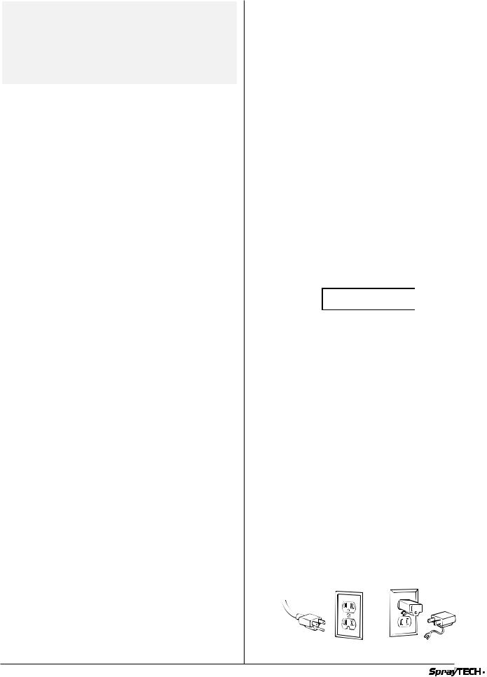
This product is for use on a nominal 120 volt circuit and has a grounding plug that looks like the plug illustrated in sketch A. If a properly grounded outlet is not available, a temporary adapter which looks like the adapter illustrated in sketch B and C may be used. The temporary adapter should be used only until a properly grounded outlet can be installed by a qualified electrician. The green colored rigid ear lug or the grounding wire extending from the adapter must be connected to a permanent ground such as a properly grounded outlet box cover. Whenever the adapter is used, it must be held in place by a metal screw.
(B)
(A) |
(C) |
|
 WARNING
Improper installation of the grounding plug can result in a risk of electric shock.
If repair or replacement of the cord or plug is necessary, do not connect the green grounding wire to either flat blade terminal. The wire with insulation having a green outer surface with or without yellow stripes is the grounding wire and must be connected to the grounding pin.
Check with a qualified electrician or serviceman if the grounding instructions are not completely understood, or if you are in doubt as to whether the product is properly grounded. Do not modify the plug provided. If the plug will not fit the outlet, have the proper outlet installed by a qualified electrician.
© SprayTECH Corporation. All rights reserved. |
3 |
English |
|
|
|

Extension Cord Selection
If an extension cord is used, make sure that it is of the 3- conductor type with NEMA connectors so a continuous grounding circuit is provided from the tool to the power circuit receptacle. Also, be sure that the conductor size is large enough to prevent excessive voltage drop which will cause loss of power and possible motor damage to the unit. A table of recommended extension cord sizes is shown below.
For nameplate ampere ratings which are between those given, use the extension cord recommended for the next higher ampere rating.
If an extension cord is to be used outdoors, it must be marked with the suffix W-A following the cord type designation. For example, SJTW-A to indicate that it is acceptable for outdoor use.
|
|
|
Extension Cord Length |
|
||||
|
|
25 ft. 50 ft. 75 ft. 100 ft. 125 ft. 150 ft. |
||||||
|
|
|
|
|
|
|
|
|
|
0 to 5 |
18 |
18 |
18 |
18 |
18 |
18 |
|
|
|
|
|
|
|
|
|
|
|
6 |
18 |
18 |
18 |
18 |
18 |
16 |
|
|
|
|
|
|
|
|
|
|
|
7 |
18 |
18 |
18 |
18 |
16 |
16 |
|
|
|
|
|
|
|
|
|
|
|
8 |
18 |
18 |
18 |
16 |
16 |
16 |
|
|
|
|
|
|
|
|
|
|
|
9 |
18 |
18 |
18 |
16 |
16 |
14 |
|
Rating |
|
|
|
|
|
|
|
|
10 |
18 |
18 |
18 |
16 |
14 |
14 |
||
|
||||||||
|
|
|
|
|
|
|
|
|
Ampere |
11 |
16 |
16 |
16 |
16 |
14 |
14 |
|
|
|
|
|
|
|
|
||
12 |
16 |
16 |
16 |
16 |
14 |
14 |
||
|
||||||||
Nameplate |
|
|
|
|
|
|
|
|
13 |
16 |
16 |
16 |
14 |
14 |
14 |
||
|
||||||||
|
|
|
|
|
|
|
|
|
|
14 |
14 |
14 |
14 |
14 |
14 |
12 |
|
|
|
|
|
|
|
|
|
|
|
15 |
14 |
14 |
14 |
14 |
14 |
12 |
|
|
|
|
|
|
|
|
|
|
|
16 |
14 |
14 |
14 |
14 |
12 |
12 |
|
|
|
|
|
|
|
|
|
|
|
17 |
14 |
14 |
14 |
14 |
12 |
12 |
|
|
|
|
|
|
|
|
|
|
|
18 |
14 |
14 |
14 |
14 |
12 |
12 |
|
|
|
|
|
|
|
|
|
|
|
19 |
12 |
12 |
12 |
12 |
12 |
12 |
|
|
|
|
|
|
|
|
|
|
|
20 |
12 |
12 |
12 |
12 |
12 |
12 |
|
Initial Setup
The Piston Pump unit is fully assembled upon delivery. Follow these simple steps for setup:
1. Pull up on the handle until the button locks snap into place.
Purging the Sprayer
This unit is shipped with test fluid in the fluid section to prevent corrosion during shipment and storage.
If you are going to spray with latex paint, the test fluid must be purged and then thoroughly cleaned out of the system.
If you are going to spray with solvent-based paint, all you need to do is purge the fluid. Thorough cleaning is not necessary.
 CAUTION
Keep the spray gun locked and in the OFF position during these steps.
Purging the System for Latex Paint
1.Place a container of soapy water under the paint suction tube. Have a waste container ready to catch the purged fluid.
2.Detach the return tube from the fluid section and place it in the waste container.
Return Tube
 WARNING
If a metal container is used, it is necessary to ground the spray gun and container. To do this, hold a metal portion of the gun against the edge of the metal container. Failure to do so may lead to static electric discharge, which may cause a fire.
3.Turn the pressure control knob counterclockwise to the lowest setting.
Pressure Control
Knob
4. Set the PRIME/SPRAY valve to the PRIME.
PRIME/SPRAY Valve
PRIME |
SPRAY |
5.Turn the ON/OFF switch to ON.
6.Turn the pressure control knob clockwise slowly until fluid starts coming through the return tube. Use the least amount of pressure necessary to keep the fluid flowing. When all of the test fluid has been cleaned out of the system, soapy water will flow through the return tube.
7.Turn the pressure control knob to its lowest setting and replace the container of soapy water with a container of clear water.
8.Turn the pressure control knob clockwise slowly until water running through the return tube is clear.
9.Turn the pressure control knob counterclockwise to the lowest setting. Replace the container of clean water with a container of latex paint.
10.Turn the pressure control knob clockwise slowly until paint comes through the return tube.
11.Place the return tube into the operating position above the paint container. Keep recirculating paint through the system until the paint coming through the return tube is free of air bubbles.
12.Turn the pressure control knob counterclockwise to the lowest setting. The unit is now ready to use.
 CAUTION
Keep the spray gun’s trigger lock in the locked position during these steps.
English |
4 |
© SprayTECH Corporation. All rights reserved. |
|
|
|

Purging the System for Solvent-Based Paint
1.Place a container of paint under the paint suction tube. Have a waste container ready to catch the purged fluid.
2.Detach the return tube from the fluid section and secure it in the waste container so that it will not come out.
Return Tube
 WARNING
If a metal container is used, it is necessary to ground the spray gun and container. To do this, hold a metal portion of the gun against the edge of the metal container. Failure to do so may lead to static electric discharge, which may cause a fire.
3.Turn the pressure control knob counterclockwise to the lowest setting.
Pressure Control
Knob
4. Set the PRIME/SPRAY valve to the PRIME.
PRIME/SPRAY Valve
PRIME |
SPRAY |
5.Turn the ON-OFF switch to ON.
6.Turn the pressure control knob clockwise slowly until fluid starts coming through the return tube. Use the least amount of pressure necessary to keep the fluid flowing. When all of the test fluid has been cleaned out of the system, paint will flow through the return tube.
7.Turn the pressure control knob to its lowest setting.
8.Place the return tube into the operating position above the paint container. Keep recirculating paint through the system until the paint coming through the return tube is free of air bubbles.
9.The unit is now ready to use.
Operating the Sprayer
Before starting spraying each day, squirt upper packing lubricant (Part No. 9992504) into the slots in the upper pump housing.
NOTE: Do not apply so much that it overflows and drips into the paint.
This lubricant keeps the piston seals pliant, minimizing paint bypass and piston wear. If the unit is operated several hours a day, lubricate approximately every 4 hours.
For a new unit, follow the purging steps above. For units already in service, purge water or solvent from the system as described above, depending on the type of paint being used.
After the pump is ready to spray, it may also be necessary to purge the hoses of water or solvent.
1.Make certain that the current limit switch is on the desired setting.
2.Turn the pressure control knob counterclockwise to the lowest setting.
3.Set the PRIME/SPRAY valve to SPRAY.
4.Be sure that the spray gun does not have a tip installed.
5.Move the gun’s trigger lock to the unlocked position.
6.Turn the pressure control knob clockwise to the halfway point to increase the pressure.
7.Trigger the gun into a waste container until solvent or water is purged from the hose.
 WARNING
If a metal container is used, it is necessary to ground the spray gun and container. To do this, hold a metal portion of the gun against the edge of the metal container. Failure to do so may lead to static electric discharge, which may cause a fire.
8.Turn the pressure control knob counterclockwise to its lowest setting.
9.Turn the PRIME/SPRAY knob to PRIME.
10.Trigger the gun to be sure no pressure is left in the hose.
11.Move the gun’s trigger lock to the locked position.
12.Install the spray tip appropriate for the material being sprayed. The thicker the paint, the larger the spray tip required.
13.Set the PRIME/SPRAY valve to SPRAY.
14.Turn the pressure control knob clockwise to its highest setting.
15.Move the gun’s trigger lock to the unlocked position.
16.Trigger the gun to test the spray pattern. Spray against a scrap piece of cardboard or other test surface.
17.Adjust the unit to the proper pressure setting.
© SprayTECH Corporation. All rights reserved. |
5 |
English |
|
|
|
Setting the Pressure
The best pressure setting will vary with the type of paint and the size and type of spray tip being used. The thicker the paint, the higher the pressure will need to be.
To find the optimum pressure setting:
1.Turn the pressure control knob clockwise to its highest setting.
2.Trigger the gun and slowly turn the pressure control knob counterclockwise. Stop when you reach the lowest pressure necessary to keep the desired spray pattern and atomization.
NOTE: Until you are satisfied with the spray pattern, spray on a test surface rather than on the surface to be painted.
Using the Spray Gun
Follow the instructions that came with your spray gun.
Pressure Relief Procedure
1.Move the gun’s trigger lock to the locked position.
2.Turn the motor ON/OFF switch to OFF.
3.Place the return line into a container and hold it securely in place.
4.Turn the PRIME/SPRAY valve to the PRIME. The pressure will be relieved and fluid will dump through the return tube.
5.Relieve any pressure remaining in the hose by moving the gun’s trigger lock to the unlocked position and triggering the gun into a container.
 WARNING
Always ground the container, including the handle. Failure to do so may result in a static electric discharge, which may cause an explosion or fire.
6. Move the gun’s trigger lock to the locked position.
NOTE: Leave the PRIME/SPRAY valve on PRIME until you are ready to operate the sprayer again.
Priming the Sprayer
1.Turn the PRIME/SPRAY valve to the PRIME.
2.Put the suction tube into the paint container.
3.Turn the pressure control knob counterclockwise to the lowest setting.
4.Turn the ON/OFF switch to ON.
5.Slowly turn the pressure control knob clockwise until the paint begins to flow through the return tube.
6.Turn the pressure control knob counterclockwise to the lowest setting.
7.Set the PRIME/SPRAY valve to SPRAY.
8.Move the gun’s trigger lock to the unlocked position.
 WARNING
If a metal container is used, it is necessary to ground the spray gun and container. To do this, hold a metal portion of the gun against the edge of the metal container. Failure to do so may lead to static electric discharge, which may cause a fire.
9.Trigger the gun into a waste container. Hold it open while slowly turning the pressure control knob clockwise until paint sprays from the gun tip. Keep the gun triggered until all the air is forced out of the system and paint is flowing freely.
10.Release the trigger and move the gun’s trigger lock to the locked position.
11.Check all fluid connections for leaks. If any are found, follow the pressure relief procedure before tightening the connection.
Spraying
Spraying Technique
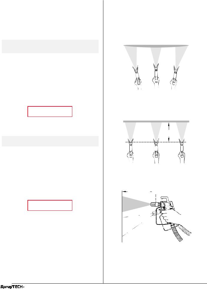
The key to a good paint job is an even coating over the entire surface. This is done by using even strokes. Keep your arm moving at a constant speed and keep the spray gun at a constant distance from the surface. The best spraying distance is 10 to 12 inches between the spray tip and the surface.
Light Coat |
Heavy Coat |
Light Coat |
Do not flex wrist while spraying.
Keep the spray gun at right angles to the surface. This means moving your entire arm back and forth rather than just flexing your wrist.
Even coat throughout
Approximately 10 to 12 inches
Keep stroke smooth and at an even speed.
Keep the spray gun perpendicular to the surface, otherwise one end of the pattern will be thicker than the other.
Approximately 10 to 12 inches
Right way
Wrong way 
The spray gun should be triggered by turning it on and off with each stroke. This will save paint and avoid paint buildup at the end of the stroke. Do not trigger the gun during the middle of a stroke. This will result in an uneven spray and splotchy coverage.
English |
6 |
© SprayTECH Corporation. All rights reserved. |
|
|
|

Proper way to trigger the spray gun
Keep stroke |
|
|
|
Approximately |
||||||||||||||||||
|
|
even |
|
|
|
10 to 12 inches |
||||||||||||||||
|
|
|
|
|
|
|
|
|
|
|
|
|
|
|
|
|
|
|
|
|
|
|
|
|
|
|
|
|
|
|
|
|
|
|
|
|
|
|
|
|
|
|
|
|
|
Start stroke |
Pull trigger |
Keep steady |
Release trigger End stroke |
Overlap each stroke by about 30%. This will ensure an even coating.
When you stop painting, lock the gun safety switch, turn the pressure control knob counterclockwise to its lowest setting and set the PRIME/SPRAY valve to PRIME. Turn the ON/OFF switch to OFF and unplug the sprayer.
Practice
1.Be sure that the paint hose is free of kinks and clear of objects with sharp cutting edges.
2.Turn the pressure control knob counterclockwise to its lowest setting.
3.Turn the PRIME/SPRAY valve to SPRAY.
4.Turn the pressure control knob clockwise to its highest setting. The paint hose should stiffen as paint begins to flow through it.
5.Move the gun’s trigger lock to the unlocked position.
6.Trigger the spray gun to bleed air out of the hose.
7.When paint reaches the spray tip, spray a test area to check the spray pattern.
8.Use the lowest pressure setting necessary to get a good spray pattern. If the pressure is set too high, the spray pattern will be too light. If the pressure is set too low, tailing will appear or the paint will spatter out in gobs rather than in a fine spray.
Most latex paints and stains will require very high pressure, which is why the sprayer is built to deliver up to 3000 PSI when needed.
Good spray pattern
Paint tailing pattern
NOTE: When spraying block filler, mastics or high solid coatings, leave out the gun filter and high pressure filter screens.
Cleanup
 WARNING
Special cleanup instructions for use with flammable solvents:
•Always flush spray gun at least one hose length from spray pump.
•If collecting flushed solvents in a one gallon metal container, place it into an empty five gallon metal container, then flush solvents.
•Area must be free of flammable vapors.
•Follow all cleanup instructions.
 CAUTION
The pump, hose, and gun should be cleaned thoroughly after daily use. Failure to do so permits material to cake, seriously affecting the performance of the unit.
After daily use, paint should be flushed from the unit with solvent compatible with the material applied, and then reflushed with mineral spirits.
 WARNING
When cleaning the pump, hose, and gun with mineral spirits or any other solvent, always spray at minimum pressure with the gun spray tip removed. Static electricity buildup may result in fire or explosion in the presence of flammable vapors.
 WARNING
Be sure to follow the pressure relief procedure when shutting the unit down for any purpose including servicing or adjusting any part of the spray system, changing or cleaning the spray tips, or preparing for cleanup.
1.Turn the ON/OFF switch to OFF.
2.Bleed off any remaining pressure in the pump by turning the PRIME/SPRAY knob to PRIME.
3.Remove the gun tip and clean it using an appropriate solvent.
4.Remove the paint container from below the suction tube.
5.Place a container of appropriate solvent below the suction tube.
6.Turn the pressure control knob counterclockwise to the lowest setting.
7.Turn the ON/OFF switch to ON.
8.Trigger the spray gun into a waste container to flush the pump, hose and gun clean.
9.Turn the ON/OFF switch to OFF.
10.Follow the pressure relief procedure detailed in this manual.
11.Unplug the unit and store it in a clean and dry area.
NOTE: For long-term storage, be sure to flush the unit with an appropriate oil before storing.
Maintenance
Daily Maintenance
Three daily procedures are required for routine operator maintenance on this unit:
1.Lubricating the upper packings.
2.Cleaning the high pressure filter screen.
3.Cleaning the intake screen.
© SprayTECH Corporation. All rights reserved. |
7 |
English |
|
|
|

Lubricating the Upper Packings
1.Clean out the paint that has seeped past the upper packings into the extension housing.
NOTE: You may need to loosen the screws on the front cover and remove the finger guard to thoroughly clean the extension housing.
Excess paint in the extension housing will adversely affect the performance of the unit.
 WARNING
Do not run the pump without the finger guard and the front cover in place. Moving parts are a tissue crushing hazard.
2.Squirt upper housing lubricant (Part No. 9992504) into the slots in the upper pump housing. If the unit is operated several hours a day, lubricate approximately every 4 hours.
NOTE: Do not apply so much lubricant that it overflows and drips into the paint.
Cleaning the High Pressure Filter Screen
The high pressure filter will clog and must be cleaned as needed.
1.Turn the filter housing counterclockwise to remove it from the filter head.
2.Take out the filter element and wash it thoroughly with the appropriate solvent. Scrub the filter with a fiber-bristled brush if necessary.
 CAUTION
Do not use a wire brush. Damage to the filter element could result.
NOTE: The filter should be cleaned at least once a day.
If you are using block fillers, mastics or other similar materials, leave the filter out.


 Filter Housing


 Filter Element
 Filter Support
O-Ring
Filter Head
Cleaning the Intake Screen
1.The intake screen will clog and must be cleaned at least once a day.
2. Turn the intake screen counterclockwise to remove it from the bottom of the suction tube.
3. Clean thoroughly with the appropriate solvent.
Suction Tube


 Intake Screen
Additional Maintenance
Repacking the Fluid Section
A small amount of paint bypassing the piston and coming out of the slots in the upper piston housing is normal. If it becomes excessive, or if paint pressure drops, the piston packings need to be replaced.
 WARNING
ALWAYS follow the PRESSURE RELIEF PROCEDURE found in your manual before starting any troubleshooting, servicing or cleaning.
 WARNING
ELECTRICAL SHOCK HAZARD. Make certain that the unit is turned off and unplugged before attempting any disassembly.
Removing the Fluid Section
1.Loosen and remove the suction tube assembly by turning it counterclockwise.
2.Remove the front cover.
3.Remove the finger guard.
4.Loosen the screw clamp and remove the return line.
5.Remove the cotter pin from the connecting pin.
6.Remove the connecting pin by pushing it through the slide block and piston rod.
7.Loosen and remove the fluid hose.
8.Loosen the large locknut on the upper end of the fluid section.
9.Unscrew the entire fluid section assembly by turning it counterclockwise.
|
Connecting Pin |
|
Cotter Pin |
Fluid Hose |
|
|
||
Screw Clamp |
Suction Tube Assembly |
|
Return Line |
||
|
||
|
Finger Guard |
 CAUTION
Do not run the motor with the fluid assembly removed.
English |
8 |
© SprayTECH Corporation. All rights reserved. |
|
|
|

Removing the Piston Rod Assembly
Refer to the parts listing for the fluid section assembly.
1.Position the inlet valve housing (26) in a vise so that the fluid section is vertical. Tighten the vise.
2.Position a large adjustable wrench on the wrench flats of the cylinder (8). Turn the cylinder counterclockwise until the cylinder is removed from the inlet valve housing.
3.Remove the inlet valve housing from the vise. Tap out the inlet ball cage (22) and ball stop pin (21).
NOTE: If any parts are difficult to disassemble, soak them in an appropriate solvent until the paint softens.
4.Remove the inlet valve carbide seat (24). Inspect the inlet valve ball and the inlet ball seat for damage. If the seat is worn or damaged, it can be flipped to the unused side. If you flip or replace the seat, the ball must be replaced.
NOTE: If the carbide valve seat requires replacement, use valve kit P/N 0294979.
5.Remove the inlet valve seat O-ring (25) from the inlet valve housing.
6.Position the wrench flats of the cylinder (8) in a vise and tighten the vise.
 CAUTION
Do not over tighten or you might damage the cylinder.
7. Remove the packing nut (1).
 CAUTION
Hold a hand under the piston rod (16). The piston rod may be damaged if it falls. The lower packings may also fall out.
8.Gently tap down the piston assembly with a rubber mallet until the piston assembly comes out.
Cleaning the Piston Rod
1.Remove the cylinder from the vise.
2.Position the piston rod assembly in the vise and tighten.
 CAUTION
The piston rod may be damaged if you are using a vise with steel jaws. Use a vise with aluminum jaws or take precautions to protect the piston rod.
3.Remove the retaining nut (20).
4.Remove the outlet valve seat (19), the outlet ball (18), the seal washer (27) and the outlet ball cage (17). Inspect the outlet valve ball and the outlet valve ball seat for damage. If the seat is worn or damaged, it can be flipped to the unused side. If you flip or replace the seat, the ball must be replaced.
5.Remove the lower packings (12, 13), the pressure ring (11), the wave washer (10), and the O-ring (9) from the cylinder (8).
6.Soak the new leather packings in linseed oil for 5 minutes. Do not over-soak.
7.Clean the disassembled parts in an appropriate solvent.
8.Install the outlet ball cage (17), the outlet ball (18), the seal washer (27), and the outlet valve seat (19) in that order into the piston rod.
9.Apply removable threadlocking compound to the retaining nut threads (20) and screw the retaining nut into the piston rod. Torque the retaining nut to 24 ft./lbs. Remove the piston assembly from the vise.
Replacing the Packings
1.Position the wrench flats of the cylinder (8) into the vise and tighten the vise.
2.Insert the wave spring (6), pressure ring (5), upper packings (3, 4) and adapter (2) into the cylinder (8).
NOTE: Make certain to alternate the UHMWPE and leather packings as shown in the illustration.
3.Loosely thread the packing nut (1) into the cylinder.
4.Remove the cylinder from the vise, rotate it, and replace it in the vise so that the bottom of the cylinder is facing up.
5.Insert the wave spring (10), the lower pressure ring (11), the lower packings (12, 13), the lower ring support (14), and the O-ring (15) into the cylinder.
Inserting the Piston Rod
1.Insert the piston rod assembly into the cylinder.
2.Insert the O-ring (25) into the inlet valve housing (26).
3.Insert the inlet ball seat (24) and the inlet ball (23) into the inlet valve housing.
4.Insert the stop pin (21) into the inlet ball cage (22) and place them into the inlet valve housing (26).
5.Place the O-ring (9) into the inlet valve housing.
6.Thread the inlet valve housing assembly onto the bottom of the cylinder assembly. Torque to 75 ft./lbs.
7.Install the large locknut (7) onto the cylinder and turn it until the nut bottoms out on the threaded section of the cylinder.
Attaching the Fluid Section
1.Remove the assembled fluid section from the vise. Apply anti-seize compound on the upper cylinder threads and thread it into the pump housing. The piston rod (16) will align itself with the slide block.
2.Rotate the fluid section so that the hole in the slide block is aligned with the hole in the piston assembly.
3.Slide the connecting pin through the holes in the slide block and the piston assembly.
4.Replace the cotter pin to hold the connecting pin securely. Refer to the illustration on the previous page.
5.Screw the fluid section into the pump housing as far as it will go. Then unscrew it slightly so that the outlet elbow will align with the fluid hose.
6.Firmly tighten the locknut (7) by turning it clockwise until it is secured tightly against the drive housing. Torque to 150 ft./lbs.
Replacing the Motor Brushes
Brushes should be inspected periodically for wear. If one of the brushes measures less than 1/2", is worn or is chipped, then replace both of the motor brushes. It is recommended that the brushes be replaced when the packings are replaced.
 WARNING
ALWAYS follow the PRESSURE RELIEF PROCEDURE found in your manual before starting any troubleshooting, servicing or cleaning.
© SprayTECH Corporation. All rights reserved. |
9 |
English |
|
|
|

Removing the Motor Cord
1.Disconnect the power cord from the electrical supply.
2.Loosen the 4 hex socket head allen screws along the sides of the motor cover and remove the cover.
3.Unscrew and remove the brush caps holding the brushes in place.
4.Pry the brushes out gently with a screwdriver.
5.Install the new brushes, P/N 07101.
6.Install the brush caps. If the old brush caps are damaged, replace them with P/N 07103.
7.Replace the motor cover and hex socket head allen screws.
Replacing the Armature
Removing the Motor Cord
1.Disconnect the unit from the power source and follow the pressure relief procedure found in this manual.
2.Remove the motor cover by unscrewing the 4 hex socket head screws that attach the shroud to the adapter plate.
3.Remove the pressure control box cover plate by unscrewing the 4 black phillips head screws.
4.Unplug the slip-on connector for the black motor lead from M1 located on the front edge of the circuit board. Then unplug the slip-on connector for the white motor lead from M2. See the wiring diagram in the parts listing section of this manual.
 Black Lead
M1
M2 |
White Lead |
|
M2 |
||
|
Cover Plate
NOTE: Pay attention to the length of the cord jacket extending into the box and the routing of both wires to the circuit board. You will need to know this when replacing the motor cord.
5.Remove the strain relief holding the motor cord in the cart mounting plate of the pressure control box. Carefully pull the motor cord out through the strain relief hole.
Installing the New Armature
Refer to the illustration below during the following steps.
7
6
4 5 
3
2  1
1
1.Unscrew the motor brush caps (1) and remove the motor brushes (2).
2.Put an alignment mark on the motor shell and gearbox so that when it is reassembled, the motor will be oriented correctly.
3.Remove the 4 long phillips head screws (3) running the length of the motor body.
4.Carefully remove the motor body (4) by pulling straight back towards the back of the cart. The armature (6) will normally remain mounted to the gearbox (7) as the motor body is being removed.
5.Remove the armature by grasping it around the middle section and pulling straight back. If there is any resistance, gently rock the armature up and down while pulling. If the armature came off with the motor body, simply pull the armature out by grasping the armature bearing.
6.Retrieve the 2 belleville washers (5) from the inside rear bearing bore in the motor end bell.
7.With the motor body sitting upright, install the belleville washers in the rear bearing bore of the motor and bell. Stack the washers so that the inside diameters touch each other.
8.Install the new armature into the motor body.
9.With the armature installed in the motor body, insert the front armature bearing in the gearbox bearing bore. The inside diameter of the motor shell should slip over the 4 centering bosses on the gearbox.
10.Align the marks on the motor shell and gearbox and attach the motor body to the gearbox with the 4 long phillips head screws.
Replacing the Motor Cord
1.Insert the motor cord through the strain relief hole on the pressure control mounting plate on the cart. Position the jacketed portion of the motor cord at the distance through the hole noted in step 4 of Removing the motor cord.
Reconnect the slip-on connector for the black motor lead to M1 and white motor lead to M2 on the front edge of the circuit board. Route the wires as noted in step 4.
2.Install the strain relief on the back side of the pressure control mounting plate.
3.Screw on the pressure control box cover plate.
4.Inspect the motor brushes for damage or wear. If less than 1/2" long, replace the brushes. Install the brushes and brush caps.
5.Replace the motor cover and mounting screws.
English |
10 |
© SprayTECH Corporation. All rights reserved. |
|
|
|
Problem
The unit will not run
The unit will not prime.
The unit will not build or maintain pressure.
Fluid leaks from the upper end of the fluid section.
The spray pattern is bad.
The pressure is low.
The fuse at the pump circuit breaker is blown.
Low performance/circuit breaker tripping.
Troubleshooting
Cause
1.A breaker is tripped on the unit or at the plug in.
2.The unit is not plugged in.
3.The pressure control knob is set too low.
4.There is faulty wiring or a faulty circuit.
5.The motor brushes are worn.
6.The ON/OFF switch is faulty.
1. The piston packings are dried out.
Solution
1.Check the breakers and reset if necessary.
2.Plug the unit in.
3.Increase the pressure.
4.Take the unit to an Authorized Service Center.
5.Check the brushes and replace if necessary
6.Take the unit to an Authorized Service Center.
1.Remove the suction tube and feel the lower check ball to be sure that it is free. Place a full cup of paint thinner over the end of the fluid section and turn on the pump.
2.The inlet valve is leaking.
3.The pump inlet screen is plugged.
4.There is air in the pump or the paint hose.
5.The piston packings are worn.
6.The paint is too thick.
7.The siphon tube is clogged.
8.The siphon tube has an air leak.
9.The tip is clogged.
1.The pressure adjustment knob is not properly set.
2.The pump inlet strainer is dirty.
3.The valve balls or valve seals are worn or dirty.
4.There is air in the pump or paint hose.
5.The piston packings are worn.
6.The spray tip is worn.
7.The unit is leaking internally.
8.The inlet or outlet valve is leaking.
9.The external fittings are leaking.
10.The paint is too thick.
11.The spray tip is too large.
12.Paint has built up on the slide block in the extension housing.
13.The PRIME/SPRAY valve is leaking.
1.The upper packing is worn.
2.The piston rod is worn.
1.The tip is too large.
2.The pressure is set incorrectly.
3.Not enough fluid is reaching the spray gun.
4.The fluid is too thick.
1.The pressure is set too low.
2.The power supply is the wrong voltage.
3.The extension cord is too long.
4.Current limit is set to 15 amp setting.
1.Pressure build up at the pump is too great.
2.There is a malfunction in the gear box or linkages.
1.Loose motor shunt wires or worn brushes.
2.Loose connections in pressure control box.
3.Safety shutoff pressure incorrect.
4.Missing circuit breaker switch boot/dirty switch.
5.The current limit switch position is incorrect.
6.The slide block or extension housing is clogged.
7.Filter is clogged.
2.Replace the inlet valve with the kit P/N 0294979.
3.Remove the inlet screen and clean.
4.Hold the gun trigger in the open position and run the unit for about 10 seconds until the air is purged. Check the suction tube for leaks.
5.Replace the packings with kit P/N 0294978.
6.Prime the pump with compatible solvent. Bring the pump up to pressure. Carefully remove the pump from the solvent container and immerse the inlet tube in the thick fluid to be sprayed. With the spray tip removed, trigger the gun until the thick fluid appears at the gun. Replace the spray tip.
7.Remove and clean the suction tube.
8.Check the suction tube and seal any leaks found.
9.Relieve the pressure; remove and clean the tip.
1.Increase the pressure.
2.Clean the pump inlet strainer.
3.Replace or clean the valve balls and seats.
4.Hold the gun trigger in the open position and run the unit for about 10 seconds until the air is purged.
5.Replace the packings with kit P/N 0294978.
6.Replace the spray tip by following the directions supplied with your spray gun.
7.With the gun trigger closed, allow the unit to come up to pressure and then shut it off when the pump momentarily starts. Look to see where the internal leak is occurring and rebuild the fluid section.
8.Replace the valves by using kit P/N 0294979.
9.Check all hose fittings and connections for external leaks.
10.Check the fluid manufacturer's recommendations listed on the fluid container label.
11.Change the spray tip.
12.Clean the slide block.
13.Check the PRIME/SPRAY valve and clean if necessary. Put in spray position firmly.
1.Relieve the pressure and replace the packings.
2.Replace the piston rod.
1.Change to a smaller spray tip.
2.Reset the pressure.
3.Clean all the strainers and filters.
4.Add solvent or water according to the fluid manufacturer's recommendations.
1.Increase the pressure.
2.Connect the unit to a 120 volt AC connection.
3.Use a 12 gauge extension cord that does not exceed 100 ft. (31 meters) in length.
4.Set switch to 20 amp setting.
1.Take the unit to a factory Authorized Service Center.
2.Repair or replace the malfunctioning parts.
1.Replace brushes and wires as necessary.
2.Tighten connections or scrape residue off of connectors.
3.Recalibrate the safety shutoff pressure to 2650 +100/-0 psi.
4.If the circuit breaker switch is clogged with contaminates, replace switch.
5.The unit should be placed in the 15 amp mode only when the wall circuit breaker is tripping. When the unit is in the 15 amp mode, it is normal for it to slow down.
6.Clean.
7.Clean the filter. If spraying heavier materials such as block filler or mastics, remove the filter.
© SprayTECH Corporation. All rights reserved. |
11 |
English |
|
|
|
|
|

Table des matières |
|
|
|
Mesures de sécurité |
|||||||
Spécifications . . . . . . . . . . . . . . . . |
. . . . . . . . . . . . . . . . . . |
12 |
|
Le présent manuel comprend des renseignements devant être |
|||||||
Mode 20 A. . . . . . . . . . . . . . . . . |
. . . . . . . . . . . . . . . . . . |
. 12 |
|
lus attentivement avant toute utilisation de l'appareil. Lorsque |
|||||||
Mode 15 A. . . . . . . . . . . . . . . . . |
. . . . . . . . . . . . . . . . . . |
. 12 |
|
l'un des symboles suivants apparaît, il est recommandé d'être |
|||||||
Mesures de sécurité . . . . . . . . . . . |
. . . . . . . . . . . . . . . . . . |
12 |
|
particulièrement attentif et de tenir compte des mesures de |
|||||||
Directives sur la mise à la terre . . |
. . . . . . . . . . . . . . . . . |
. 13 |
|
sécurité indiquées. |
|||||||
Choix d'une rallonge . . . . . . . . . |
. . . . . . . . . . . . . . . . . . |
. 14 |
|
|
|
|
|
|
|
|
|
|
|
|
|
AVERTISSEMENT |
|
|
|||||
Purge du pistolet . . . . . . . . . . . . |
. . . . . . . . . . . . . . . . . . |
. 14 |
|
|
|
|
|||||
Installation initiale. . . . . . . . . . . . . |
. . . . . . . . . . . . . . . . . . |
14 |
|
|
|
|
|
|
|
|
|
Fonctionnement du pistolet |
|
15 |
|
|
|
|
|
|
|
|
|
. . . . . . . . . . . . . . . . . . |
|
Ce symbole indique un danger potentiel pouvant causer des |
|||||||||
Réglage de la pression |
|
16 |
|
||||||||
. . . . . . . . . . . . . . . . . . |
|
blessures graves ou même mortelles. Des renseignements |
|||||||||
Utilisation du pistolet . . . . . . . . . |
. . . . . . . . . . . . . . . . . . |
. 16 |
|
importants sur la sécurité sont également présentés. |
|||||||
Procédure relative à l’élimination de la pression. . . . . . . . |
16 |
|
|
|
|
|
|
|
|
||
Amorçage du pistolet. . . . . . . . . |
. . . . . . . . . . . . . . . . . . |
. 16 |
|
|
|
|
ATTENTION |
|
|
|
|
Pulvérisation . . . . . . . . . . . . . . . . . |
. . . . . . . . . . . . . . . . . . |
16 |
|
|
|
|
|
||||
Technique de pulvérisation |
|
16 |
|
|
|
|
|
|
|
|
|
. . . . . . . . . . . . . . . . . |
|
Ce symbole indique un danger potentiel pouvant causer des |
|||||||||
Exercice . . . . . . . . . . . . . . . . . . |
. . . . . . . . . . . . . . . . . . |
. 17 |
|
||||||||
Nettoyage . . . . . . . . . . . . . . . . . . . |
. . . . . . . . . . . . . . . . . . |
17 |
|
blessures graves ou même mortelles. Des renseignements |
|||||||
Entretien . . . . . . . . . . . . . . . . . . . . |
. . . . . . . . . . . . . . . . . . |
18 |
|
importants sur la sécurité sont également présentés.. |
|||||||
Entretien quotidien |
|
18 |
|
|
|
|
|
||||
. . . . . . . . . . . . . . . . . . |
|
|
NOTA: Les remarques donnent des renseignements |
|
|||||||
Entretien additionnel . . . . . . . . . |
. . . . . . . . . . . . . . . . . . |
. 18 |
|
|
importants requérant une attention particulière. |
|
|||||
En cas de problème . . . . . . . . . . . |
. . . . . . . . . . . . . . . . . . |
21 |
|
|
|
|
|
|
|
|
|
Liste des pièces |
|
32 |
|
|
|
|
|
|
|
|
|
. . . . . . . . . . . . . . . . . . |
|
|
|
AVERTISSEMENT |
|
|
|||||
Assemblage final . . . . . . . . . . . . |
. . . . . . . . . . . . . . . . . . |
. 32 |
|
|
|
|
|
||||
Ensemble d’entraînement . . . . . . |
. . . . . . . . . . . . . . . . . |
. 34 |
|
|
|
|
|
|
|
|
|
. . . . . . . . . . . . . . .Ensemble de commande de pression |
36 |
|
DANGER: BLESSURES PAR PERFORATION - Le jet de |
||||||||
Ensemble moteur . . . . . . . . . . . |
. . . . . . . . . . . . . . . . . . |
. 38 |
|
||||||||
Ensemble de transducteur |
|
39 |
|
|
peinture à haute pression produit par cet |
||||||
. . . . . . . . . . . . . . . . . |
|
|
appareil peut perforer la peau et les tissus |
||||||||
Ensemble de la section du fluide |
|
40 |
|
|
|||||||
. . . . . . . . . . . . . . . . . |
|
|
sous-jacents et entraîner de sévères blessures |
||||||||
. . . . . .Assemblage filtre/soupape |
. . . . . . . . . . . . . . . . . |
. 41 |
|
|
pouvant nécessiter une amputation. |
||||||
Ensemble de la soupape AMORÇAGE-VAPORISATION . 42 |
|
|
|||||||||
|
|
|
|
|
|
|
|
||||
Ensemble du support |
|
42 |
|
|
|
|
|
|
|
|
|
. . . . . . . . . . . . . . . . . . |
|
|
NE PAS TRAITER UNE BLESSURE PAR PERFORATION |
|
|||||||
Accessoires. . . . . . . . . . . . . . . . |
. . . . . . . . . . . . . . . . . . |
. 43 |
|
|
COMME UNE SIMPLE COUPURE! Une perforation peut |
|
|||||
Filters du pistolet . . . . . . . . . . . . |
. . . . . . . . . . . . . . . . . . |
. 44 |
|
|
entraîner des risques d'amputation. Consultez |
|
|||||
Schéma de câblage de l’ensemble de commande de pression . 45 |
|
|
immédiatement un médecin. |
|
|||||||
Garantie limitée . . . . . . . . . . . . . . . |
. . . . . . . . . . . . . . . . . . |
47 |
|
|
|
|
|
|
|
|
|
|
|
MESURES PRéVENTIVES: |
|||||||||
Spécifications |
|
|
|
||||||||
|
|
|
|
• Pression de service maximale du fluide dans l’appareil : |
|||||||
Modèle EP2510 120V |
|
|
|
|
3000 lb/po2. |
||||||
|
|
|
|
• NE JAMAIS diriger le pistolet vers une quelconque partie |
|||||||
|
|
|
|
|
|
||||||
Mode 20 A |
|
|
|
|
du corps. |
||||||
Litres / minute . . . . . . . . . . . . . . . . |
5,68 |
|
|
|
• NE JAMAIS mettre une quelconque partie du corps en |
||||||
Réservoir de fluide |
Garniture statiqueà deux |
|
|
contact avec le jet de liquide. NE JAMAIS se mettre au |
|||||||
|
|
contact d'un jet de liquide provenant d'une fuite du flexible |
|||||||||
|
|
cycles et sièges de |
|
|
|
||||||
|
|
|
|
|
d'alimentation en liquide. |
||||||
|
|
soupape réversibles |
|
|
|
||||||
|
|
|
|
|
• NE JAMAIS placer votre main devant le pistolet. Des |
||||||
Pression maximale |
206 bar |
|
|
|
|||||||
|
|
|
gants ne vous protégeront pas contre les risques de |
||||||||
. . . . .Moteur électrique (universel) |
1,5 HP |
|
|
|
blessures par perforation. |
||||||
Intensité du courant . . . . . . . . . . . . |
17 A |
|
|
|
• TOUJOURS verrouiller la gâchette du pistolet, fermer la |
||||||
Protection électrique . . . . . . . . . . . |
Disjoncteur de 22 A |
|
|
|
pompe à liquide et décompresser l'appareil lorsque vous |
||||||
Dimension maximale de l’embout |
Un pistolet : 0,09 cm; |
|
|
|
travaillez sur celui-ci, nettoyez le protecteur de tête, |
||||||
|
|
|
remplacez la tête de pulvérisation ou vous éloignez de |
||||||||
|
|
Deux pistolets : 0,06 cm |
|
|
|
||||||
|
|
|
|
|
l'appareil. Couper le moteur ne décompresse pas l'appareil. |
||||||
Longueur du boyau |
91,44 m |
|
|
|
|||||||
|
|
|
Vous devez, pour le décompresser, placer le bouton |
||||||||
. . . . . . . . . . . .Rallonge maximale |
30,48 m; calibre 12 |
|
|
|
AMORÇAGE/PULVÉRISATION en position AMORÇAGE. |
||||||
Poids. . . . . . . . . . . . . . . . . . . . . . |
. 4,99 kg |
|
|
|
Reportez-vous, pour cela, à la PROCÉDURE DE |
||||||
Dimensions . . . . . . . . . . . . . . . . . . |
84 cm L x 104 cm H x |
|
|
|
DÉCOMPRESSION décrite dans de ce manuel. |
||||||
|
|
66 cm W |
|
|
|
• TOUJOURS s'assurer que le protecteur de tête est en place |
|||||
Mode 15 A |
|
|
|
|
lorsque vous pulvérisez. Le protecteur de tête offre une |
||||||
|
|
|
|
certaine protection contre les blessures par perforation mais |
|||||||
Litres / minute |
3,64 |
|
|
|
|||||||
|
|
|
sa principale fonction est d'ordre préventif. |
||||||||
Réservoir de fluide |
Garniture statiqueà deux |
|
|
||||||||
|
|
• TOUJOURS ôter la tête de pulvérisation avant de purger |
|||||||||
|
|
cycles et sièges de |
|
|
|
ou nettoyer l'appareil. |
|||||
|
|
soupape réversibles |
|
|
|
||||||
|
|
|
|
|
• Le flexible d'alimentation en peinture peut fuir à la suite |
||||||
Pression maximale |
206 bar |
|
|
|
|||||||
|
|
|
d'une usure, de chocs ou de mauvais traitements. Une |
||||||||
Moteur électrique (universel) . . . . . |
1,5 HP |
|
|
|
fuite peut entraîner une perforation de la peau. Inspecter |
||||||
Intensité du courant . . . . . . . . . . . . |
17 A |
|
|
|
le flexible avant chaque utilisation. |
||||||
Protection électrique . . . . . . . . . . . |
Disjoncteur de 20 A |
|
|
|
• NE JAMAIS utiliser un pistolet dont la gâchette n'est pas |
||||||
Dimension maximale de l’embout |
Un pistolet : 0,07 cm; |
|
|
|
munie d'un loquet ou un cran de sécurité qui soit enétat |
||||||
|
|
|
de fonctionner. |
||||||||
|
|
Deux pistolets : 0,05 cm |
|
|
|
||||||
|
|
|
|
|
• Tous les accessoires doivent être homologués pour une |
||||||
Longueur du boyau |
60,96 m |
|
|
|
|||||||
|
|
|
pression égale ou supérieure à 3000 lb/po2. Cela |
||||||||
. . . . . . . . . . . .Rallonge maximale |
30,48 m; calibre 12 |
|
|
|
s'applique, entre autres, aux têtes de pulvérisation, aux |
||||||
Poids. . . . . . . . . . . . . . . . . . . . . . |
. 4,99 kg |
|
|
|
accessoires du pistolet et aux flexibles. |
||||||
Dimensions . . . . . . . . . . . . . . . . . . |
84 cm L x 104 cm H x |
|
|
|
• En cas d’injection dans la peau, consulter un médecin |
||||||
|
|
66 cm W |
|
|
|
immédiatement. |
|||||
Français |
12 |
© SprayTECH Corporation. Tous droits réservés. |
AVERTISSEMENT AUX MÉDECINS :
Une perforation sous-cutanée constitue un traumatisme. Il est important de traiter la blessure de façon chirurgicale aussitôt que possible. NE RETARDEZ PAS ce traitement pour des recherches de toxicité. La toxicité n'est un risque que dans les cas où certains produits de revêtement pénètrent dans le flux sanguin. Il peut être nécessaire de faire appel à des soins de chirurgie plastique ou de reconstruction de la main.
DANGER: RISQUES D'EXPLOSION OU D'INCENDIE - Les vapeurs dégagées par le solvant ou la peinture sont explosives et inflammables et peuvent causer des dommages matériels ou corporels sérieux.
MESURES PRéVENTIVES:
•Veiller à éviter toute accumulation de vapeurs inflammables en vous assurant que la zone où la pulvérisation a lieu est suffisamment ventilée.
•Veiller à éviter la présence de toute source incandescente telle qu'étincelle électrostatique, flamme nue, flammepilote, objet brûlant, cigarette et étincelle provenant du branchement ou du débranchement d'un cordon d'alimentation électrique ou d'un commutateur.
•Toujours avoir un extincteur en état de fonctionner à portée de la main.
•Garder l’appareil dans un endroit bien aéré, à l’écart de la zone de pulvérisation, afin d’éloigner les vapeurs de solvant et de peinture. La pompe contient des pièces produisant des arcs et émettant des étincelles.
•La vitesse élevée du produit dans l'appareil peut causer l'accumulation d'électricité statique. Le matériel utilisé, ainsi que les objets se trouvant à proximité de la zone de pulvérisation, doivent être convenablement reliés à la terre afin d'éviter toute étincelle ou toute décharge électrostatique.
•N'utiliser que des flexibles d'alimentation en liquide à haute pression conducteurs ou reliés à la terre dans les cas d'utilisation sans air comprimé. S'assurer que le pistolet est convenablement relié à la terre par l'intermédiaire du flexible.
•Le cordon d’alimentation doit être raccordé à un circuit mis à la terre.
•S’entourer de toutes les précautions possibles lorsqu’on utilise des produits ayant un point d’éclair inférieurà 21 °C (70 °F). Le point d’éclair d’un fluide est la température à laquelle les vapeurs émanant du fluide peuvent s’enflammer au contact d’une flamme ou d’une étincelle.
•Se conformer aux consignes et recommandations de sécurité du fabricant du solvant ou du produit.
•Lorsque vous purgez l'appareil, veillez à utiliser à la pression minimale.
DANGER: RISQUES D'EXPLOSION PAR INCOMPATIBILITÉ DES MATÉRIAUX - Peuvent être à l'origine de dommages matériels ou corporels sérieux.
MESURES PRéVENTIVES:
•Ne pas utiliser d'eau de Javel.
•Ne pas se servir de solvants aux hydrocarbures halogénés comme le chlorure de méthylène et le trichloroéthane-1,1,1. Ces produits ne sont pas compatibles avec l’aluminium et peuvent causer une explosion. En cas de doute sur la compatibilité d’un produit avec l’aluminium, communiquer avec son fournisseur de revêtement.
DANGER: VAPEURS TOXIQUES - La peinture, les solvants, les insecticides et d'autres produits peuvent être toxiques s'ils sont inhalés et provoquer des nausées graves, des évanouissement ou des empoisonnements.
MESURES PRéVENTIVES:
•Utiliser un respirateur ou un masque chaque fois qu'il y a des risques d'inhalation de vapeurs. Lire attentivement toutes les instructions se rapportant au masque pour vérifier que celui-ci vous assure une protection suffisante contre les vapeurs toxiques.
DANGER: GÉNÉRALITÉS - Peut causer des dommages matériels ou corporels sérieux.
MESURES PRéVENTIVES:
•Avant d'utiliser tout équipement, lire attentivement toutes les instructions et les consignes de sécurité
•Se conformer à la législation locale, provinciale ou fédérale pour tout ce qui concerne la ventilation, la prévention des incendies et les conditions générales d'utilisation.
•Les normes de sécurité du Gouvernement américain sont régies par le Occupational Safety and Health Act (OSHA). Il est important de consulter ces normes, en particulier la section 1910 sur le normes générales et la section 1926 sur les des normes de la construction.
•Cette pompe à haute pression sans air comprimé est conçue pour être utilisée uniquement avec des pièces agrées par le fabricant. Toute utilisation de l'appareil avec des pièces non conformes aux exigences techniques de base et de sécurité du fabricant est aux risques et périls de l'utilisateur.
•Vérifier, avant toute utilisation, que les flexibles ne présentent pas d'entaille ou de fuite, que le couvercle ne soit pas gonflé et que les raccords ne soient pas endommagés. Si le flexible a subi l'un des dommages précités, remplacez-le immédiatement. Ne jamais réparer un flexible d'alimentation en peinture. Le remplacer par un autre flexible mis à la terre.
•Tout flexible, raccord orientable, pistolet et accessoire utilisé avec cet appareil doit pouvoir fonctionner à une pression égale ou supérieure à 2750 lb/po2.
•Ne jamais pulvériser lorsqu'il vente.
•Porter des lunettes de protection.
 ATTENTION
Utiliser uniquement une rallonge trifilère dotée d'une fiche de mise à la terre à trois broches et d'une prise à trois fentes pouvant accepter la fiche sur le produit. S'assurer que la rallonge est en bon état. S'assurer également que cette dernière convient au courant consommé par l'appareil. Une rallonge de section inférieure produira une perte de tension, entraînant une perte de puissance et la surchauffe. Une rallonge de calibre de 12 ou 14 est recommandée.
Directives sur la mise à la terre
Ce dispositif doit être mise à la terre. En cas de court-circuit, ce procédé permet de réduire le risque d'un chocélectrique en fournissant un fil d'évacuation pour le courant. Ce produit est équipé d'un cordon comportant un fil de miseà la terre muni d'une fiche appropriée. Cette fiche doit être branchée sur une prise adéquatement installée et mise à la terre selon les codes et règlements locaux en vigueur.
Ce produit peut être utilisé sur un circuit minimal de 120 volts. Il comporte une fiche mise à la terre semblable à celle illustrée dans le schéma A. En l'absence d'une prise adéquatement mise à la terre, un adapteur temporaire ressemblant à celui présenté dans les schémas B et C peutêtre utilisé. L'adapteur temporaire ne doit être utilisé qu'en attendant l'installation d'une prise appropriée par un électricien qualifié. La languette rigide verte, ou le fil de mise à la terre provenant de l'adapteur, doit être connecté à un base permanente correctement mise à la terre, tel le couvercle de la boîte de sortie. Lors de son utilisation, l'adapteur doit être maintenu en place au moyen d'une vis métallique.
(B)
(A) |
(C) |
|
© SprayTECH Corporation. Tous droits réservés. |
13 |
Français |
|
|
|

 AVERTISSEMENT
Une installation inadéquate de la fiche de mise à la terre risque de provoquer un choc électrique.
S'il est nécessaire de réparer ou de remplacer le cordon ou la fiche, ne pas connecter le fil de miseà la terre vert à aucune des bornes à broches plates. Le fil comportant un isolant de couleur verte, avec ou sans lignes jaunes, est le fil de miseà la terre devant être connecté à la broche de mise à la terre.
Il est recommandé de consulter un électricien qualifié ou un technicien, lorsque les directives portant sur la miseà la terre ne sont pas entièrement comprises, ou lorsque l'on n'est pas sûr que le produit soit correctement mis à la terre. Ne pas modifier la fiche fournie. Si la fiche ne peutêtre insérée dans la prise, demander à un électricien qualifié d'installer la prise appropriée.
Choix d'une rallonge
Si une rallonge est utilisée, s'assurer qu'il s'agit d'une rallonge trifilère dotée de connecteurs NEMA, de façon qu'un circuit de mise à la terre soit constamment fourni entre l'appareil et la prise du circuit d'alimentation. S'assurer également que le fil conducteur est suffisamment long, afin de prévenir toute perte excessive de tension; un fil de section inférieure entraînerait une perte de puissance et pourrait éventuellement causer des dommages au moteur de l'appareil. Les longueurs recommandées sont présentées dans le tableau ci-dessous.
Pour une intensité nominale (plaque signalétique) comprise entre celles indiquées, utiliser la rallonge recommandée pour la prochaine intensité nominale supérieure.
Une rallonge ne peut être utilisée à l'extérieur, que si le terme désignant son type est précédé des lettres W-A. Par exemple, SJTW-A indique que la rallonge en question peut être utilisée à l'extérieur.
|
|
Longueur de la rallonge |
|
|||||
|
|
7,6 m |
15,2 m |
22,9 m |
30,5 m |
38,1 m |
45,7 m |
|
|
|
(25 pi) |
(50 pi) |
(75 pi) |
(100 pi) (125 pi) (150 pi) |
|||
|
0 à 5 |
18 |
18 |
18 |
18 |
18 |
18 |
|
|
|
|
|
|
|
|
|
|
|
6 |
18 |
18 |
18 |
18 |
18 |
16 |
|
|
|
|
|
|
|
|
|
|
|
7 |
18 |
18 |
18 |
18 |
16 |
16 |
|
|
|
|
|
|
|
|
|
|
tique |
8 |
18 |
18 |
18 |
16 |
16 |
16 |
|
|
|
|
|
|
|
|
||
9 |
18 |
18 |
18 |
16 |
16 |
14 |
||
signalé |
||||||||
|
|
|
|
|
|
|
||
10 |
18 |
18 |
18 |
16 |
14 |
14 |
||
|
||||||||
plaque- |
|
|
|
|
|
|
|
|
12 |
16 |
16 |
16 |
16 |
14 |
14 |
||
|
11 |
16 |
16 |
16 |
16 |
14 |
14 |
|
nominale |
|
|
|
|
|
|
|
|
14 |
14 |
14 |
14 |
14 |
14 |
12 |
||
|
13 |
16 |
16 |
16 |
14 |
14 |
14 |
|
é |
|
|
|
|
|
|
|
|
Intensit |
15 |
14 |
14 |
14 |
14 |
14 |
12 |
|
|
||||||||
|
|
|
|
|
|
|
|
|
|
16 |
14 |
14 |
14 |
14 |
12 |
12 |
|
|
|
|
|
|
|
|
|
|
|
17 |
14 |
14 |
14 |
14 |
12 |
12 |
|
|
|
|
|
|
|
|
|
|
|
18 |
14 |
14 |
14 |
14 |
12 |
12 |
|
|
|
|
|
|
|
|
|
|
|
19 |
12 |
12 |
12 |
12 |
12 |
12 |
|
|
|
|
|
|
|
|
|
|
|
20 |
12 |
12 |
12 |
12 |
12 |
12 |
|
Installation intiale
La pompe à piston est livrée entièrement assemblée. Il suffit donc, pour l'installer, d'effectuer les opérations indiquées cidessous.
1.Tirer sur le manche jusqu'à ce que les dispositifs de verrouillage du bouton s'enclenchent en place.
Purge du pistolet
Lors de sa livraison, la section pour fluide de l'appareil contient un fluide d'essais, empêchant qu'une corrosion ne se produise durant le transport et l'entreposage.
Si l'appareil est utilisé pour vaporiser une peinture au latex, ce fluide doit être évacué du système et ce dernier entièrement nettoyé.
Si par contre le système est utilisé pour vaporiser une peinture à base de solvant, il suffit d'évacuer le fluide d'essais. Un nettoyage à fond n'est pas requis.
 ATTENTION
S'assurer que le pistolet est verrouillé et réglé à la position ARRÊT lors de l'exécution des opérations suivantes.
Purge du système pour les peintures au latex
1.Placer un contenant d'eau savonneuse sous le tube de succion pour peinture. Se munir d'un contenant à déchets destiné à recevoir le fluide de décharge.
2.Détacher le tube de renvoi de la section pour fluide et le placer dans le contenant à déchets.
Tube de renvoi
 AVERTISSEMENT
Si un contenant en métal est utilisé, il est nécessaire de mettre à la terre le pistolet et le contenant. Pour ce faire, mettre en contact une partie métallique du pistolet avec le bord du contenant. Le défaut d'effectuer cette opération peut entraîner une décharge d'électricité statique et provoquer un incendie.
3.Tourner le bouton de réglage de la pression dans le sens anti-horaire, jusqu'au minimum.
Bouton de réglage de la pression
4.Régler la soupape AMORÇAGE-VAPORISATION à AMORÇAGE.
La soupape
AMORÇAGE-
VAPORISATION
AMORÇAGE VAPORISATION
5.Régler l'interrupteur MARCHE-ARRÊT à ARRÊT.
6.Tourner lentement le bouton de réglage de la pression dans le sens horaire jusqu'à ce que le fluideémerge du tube de renvoi. Utiliser une quantité de pression suffisante pour que le fluide continue de s'écouler. Une fois que tout le fluide d'essais a été évacué du système, l'eau savonneuse commencera à s'écouler du tube de renvoi.
Français |
14 |
© SprayTECH Corporation. Tous droits réservés. |
|
|
|

7.Régler le bouton de réglage de la pression au niveau le plus bas et remplacer le contenant d'eau savonneuse par un contenant d'eau claire.
8.Tourner lentement le bouton de réglage de la pression dans le sens horaire jusqu'à ce que l'eau s'écoulant du tube de renvoi soit claire.
9.Tourner le bouton de réglage de la pression dans le sens anti-horaire, jusqu'au minimum. Remplacer le contenant d'eau par un contenant de peinture au latex.
10.Tourner lentement le bouton de réglage de la pression dans le sens horaire jusqu'à ce que la peinture s'écoule du tube de renvoi.
11.Placer le tube de renvoi en position de fonctionnement audessus du contenant de peinture. Continuer à faire circuler la peinture à travers le système jusqu'à ce que la peinture s'écoulant du tube de renvoi ne comporte aucune bulle d'air.
12.Tourner le bouton de réglage de la pression dans le sens anti-horaire, jusqu'au minimum. L'appareil est maintenant prêt à être utilisé.
 ATTENTION
S'assurer que le pistolet est verrouillé et réglé à la position ARRÊT lors de l'exécution des opérations suivantes.
Purge du système pour une peinture à base de solvant
1.Placez un contenant de peinture sous le tube de succion de peinture. Se munir d'un contenant à déchets destiné à recevoir le fluide de décharge.
2.Détacher le tube de renvoi de la section pour fluide et le placer dans le contenant à déchets de façon à ce qu'il se maintienne bien en place.
 AVERTISSEMENT
Si un contenant en métal est utilisé, il est nécessaire de mettre à la terre le pistolet et le contenant. Pour ce faire, mettre en contact une partie métallique du pistolet avec le bord du contenant. Le défaut d'effectuer cette opération peut entraîner une décharge d'électricité statique et provoquer un incendie.
3.Tourner le bouton de réglage de la pression dans le sens anti-horaire, jusqu'au minimum.
Bouton de réglage de la pression
4.Régler la soupape AMORÇAGE-VAPORISATION à AMORÇAGE.
La soupape
AMORÇAGE-
VAPORISATION
AMORÇAGE VAPORISATION
5. Régler l'interrupteur MARCHE-ARRÊT à ARRÊT.
6.Tourner lentement le bouton de réglage de la pression dans le sens horaire jusqu'à ce que le fluideémerge du tube de renvoi. Utiliser une quantité de pression suffisante pour que le fluide continue de s'écouler. Une fois que tout le fluide d'essais a été évacué du système, la peinture commencera à s'écouler du tube de renvoi.
7.Régler le bouton de réglage de la pression au niveau le plus bas.
8.Placer le tube de renvoi en position de fonctionnement audessus du contenant de peinture. Continuer à faire circuler la peinture à travers le système jusqu'à ce que la peinture s'écoulant du tube de renvoi ne comporte aucune bulle d'air.
9.L'appareil est maintenant prêt à être utilisé.
Fonctionnement du pistolet
Avant de commencer toute opération de pulvérisation, injecter le lubrifiant de la garniture supérieure (no de pièce 9992504) dans les fentes du corps de la pompe supérieur.
NOTA: S'assurer de ne pas appliquer une trop grande quantité de lubrifiant, afin d'éviter que ce dernier ne s'écoule dans la peinture.
Ce lubrifiant permet aux joints du piston de conserver toute leur souplesse,
minimisant ainsi un débordement de peinture et une usure du piston. Si l'appareil est utilisé quotidiennement pendant plusieurs heures, lubrifier celui-ci approximativement toutes les 4 heures.
S'il s'agit d'un nouvel appareil, suivre les 


 étapes relatives à la purge du système
  indiquées ci-dessus. Si, par contre, l'appareil a déjà été utilisé, faire évacuer l'eau ou le solvant comme il est indiqué ci-dessus, en fonction du type de peinture utilisé.
Une fois la pompe prête à être utilisée, il peut aussi être nécessaire d'évacuer l'eau ou le solvant des flexibles.
1.S'assurer que l'interrupteur de limite du courant est réglé correctement.
2.Tourner le bouton de réglage de la pression dans le sens anti-horaire, jusqu'au minimum.
3.Régler la soupape AMORÇAGE-VAPORISATION à VAPORISATION.
4.S'assurer que le pistolet n'est pas muni d'un embout.
5.Tourner l'interrupteur de sûreté du pistolet afin de déverrouiller ce dernier.
6.Tourner le bouton de réglage de la pression dans le sens horaire jusqu'à mi-chemin, afin d'augmenter la pression.
7.Appuyez sur la détente et pulvériser dans un contenantà déchets jusqu'à ce que l'eau ou le solvant soitévacué des flexibles.
 AVERTISSEMENT
Si un contenant en métal est utilisé, il est nécessaire de mettre à la terre le pistolet et le contenant. Pour ce faire, mettre en contact une partie métallique du pistolet avec le bord du contenant. Le défaut d'effectuer cette opération peut entraîner une décharge d'électricité statique et provoquer un incendie.
8.Tourner le bouton de réglage de la pression dans le sens anti-horaire, jusqu'au minimum.
9.Régler le bouton AMORÇAGE-VAPORISATION à AMORÇAGE.
10.Appuyer sur la détente du pistolet, afin de s'assurer qu'aucune pression n'existe dans le flexible.
11.Tourner l'interrupteur de sûreté du pistolet pour le verrouiller.
12.Installer l'embout approprié au produit utilisé. Plus la peinture est épaisse, plus l'embout doit être large.
13.Régler la soupape AMORÇAGE-VAPORISATION à VAPORISATION.
© SprayTECH Corporation. Tous droits réservés. |
15 |
Français |
|
|
|
Loading...