

Splendide AW 122, AW 125, AWD 129, AWD 120, AWD 121 Training Manual
...
6SOHQGLGH¥
5&$)/*$"-&%6$"5*0/
(306113&4&/54
53"*/*/((6*%&
PRODUCT: WASHER / WASHER-DRYER COMBO
MODEL: AW 120 / AW 122 / AW 125
AWD 120 / AWD 121 / AWD 129
The information included in this Splendide Repair Manual may change without notice. Please see our web site
www.splendide.com/service/docs.html for updates, corrections or additions.
Pages:
1 - 18

AW 120 / AW 122 / AW 125
REPAIR MANUAL
AWD 120 / AWD 121 / AWD 129
SAFE SERVICE PRACTICES
This Repair Manual is intended for persons having electrical and mechanical training and a level of knowledge
of these subjects generally considered acceptable in the Appliance Service Industry. Splendide cannot be
responsible, nor assumes any liability for injury or damages of any kind arising from the use or misuse of
the information contained in this Repair Manual.
If you have any questions regarding the proper diagnosis, repair or operation of any Splendide Appliance, please
contact Splendide Division Westland Sales at 1-800-356-0766.
SERVICING SAFEGAURDS:
To avoid personal injury and/or property damage, it is important that safe servicing practices be observed at all times. Examples of
safe service practices are listed below but are not limited to the following:
1) Never attempt a product repair if you have any doubts as to your ability to complete the repair in a safe and
satisfactory manner.
2) Before servicing or removing an appliance:
- Disconnect power to the appliance.
- Turn off the gas / LP supply.
- Turn off the water supply.
3) Never interfere with the proper operation of any safety device.
4) Use only genuine factory replacement parts as substitutions may interfere with compliances to home safety codes or standards.
5) It is extremely important that all safety ground connections be reestablished prior to the completion of the service call. Failure to
do so will result in a hazardous condition being created.
6) Prior to returning the appliance back into active service, ensure the following:
- All electrical connections are correct and secure.
- Electrical leads are properly dressed and secured away from sharp edges, high temperature components and moving parts.
- All non-insulated electrical terminals, connectors, heaters, etc. are adequately spaced away from metal parts or panels.
- All safety grounds (both internal and external) are correctly and securely connected.
- All access panels are properly and securely reassembled.
Page: i

AW 120 / AW 122 / AW 125
REPAIR MANUAL
AWD 120 / AWD 121 / AWD 129
TABLE OF CONTENTS
Page
1. Model & Serial Number Locations..................................................................................................1
2. Top Panel.......................................................................................................................................2
3. Control Panel.................................................................................................................................. 3
4. Control Panel Components............................................................................................................. 4
5. Toe Kick & Drain Motor ..................................................................................................................6
6. Drum Boot...................................................................................................................................... 7
7. Door Switch....................................................................................................................................8
8. Water Valves..................................................................................................................................8
9. Heater Assembly (AWD 120 Only).......................................................................................................... 9
10. Pressure Switch............................................................................................................................ 10
11. Rear Access Panel.......................................................................................................................10
12. Control Board............................................................................................................................... 11
13. Main Motor.................................................................................................................................... 12
14. Fault Codes..................................................................................................................................13
15. Schematics................................................................................................................................... 14
Page: ii

REPAIR MANUAL
1. MODEL & SERIAL NUMBER LOCATION
AW 120 / AW 122 / AW 125
AWD 120 / AWD 121 / AWD 129
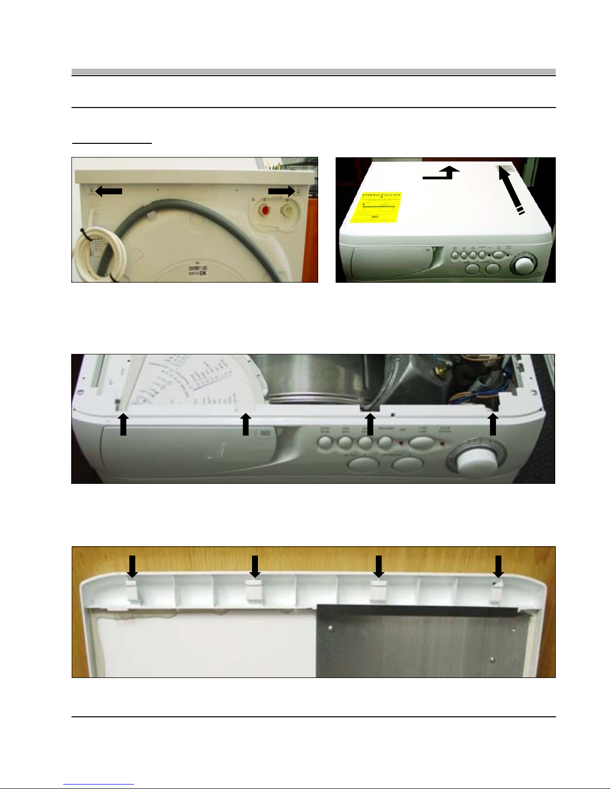
Fig. 1-1
• The Model and Serial Number Tag is located on the front of the Appliance behind the door (Fig. 1-1). The Model shown is an
AWD120 with a Serial Number of 403043152 (Fig. 1-2).
Note: Numbers located to the right of the nine (9) digit Serial Number are not required on the Warranty Claim Form.
Fig. 1-3
Fig. 1-2
• Model and Serial Number Tag located on the rear of the Appliance (Fig. 1-3).
Page: 1
2. TOP PANEL
REPAIR MANUAL
AW 120 / AW 122 / AW 125
AWD 120 / AWD 121 / AWD 129
1
2
Fig. 2-1
• To remove the Top Panel, first remove the two (2) Phillips screws located at the rear corners of the panel (Fig. 2-1). With the two
screws removed lift the rear of the panel up approximately three (3) inches and then slide the panel back, moving it away from the
Control Panel (Fig. 2-2)
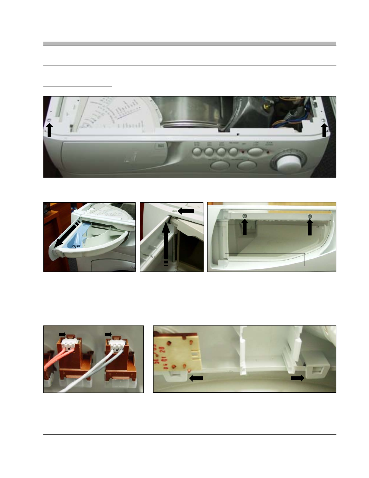
• With the Top Panel removed you can see the four (4) alignment slots on top of the Control Panel (Fig. 2-3) that correspond to the
four (4) alignment tabs on the bottom of the Top Panel (Fig. 2-4). When re-installing the panel make sure to align the tabs and
slots and then slide the panel back into place.
Fig. 2-2
Fig. 2-3
Fig. 2-4
Page: 2
AW 120 / AW 122 / AW 125
REPAIR MANUAL
AWD 120 / AWD 121 / AWD 129
3. CONTROL PANEL
• To remove the Control Panel, first remove the two Phillips screws located on the top corners of the Control Panel (Fig 3-1).
Fig. 3-1
Fig. 3-2
Fig. 3-3
Fig. 3-4
• Next, remove the Soap Dispenser by grasping it firmly and sliding it out from its housing (Fig. 3-2). Now, remove the Dispenser
Door and Program Guide by lifting out the Hinge Pin (Fig. 3-3) the pin will easily slide up and out. With the Soap Dispenser and
Door completely removed you can remove the two (2) remaining Phillips Screws.
TECH NOTE: When re-installing the Control Panel make sure the bottom edge of the Soap Dispenser Housing rests on top of the
Control Panel opening as shown in the box of Fig. 3-4.
Fig. 3-5
Fig. 3-6
• Next, remove the wiring from each Switch and the Program Selector. To remove the Switch wiring simply press the Locking Tab
forward and slide the Wiring Connector up and out (Fig. 3-5). Now release the two (2) remaining Control Panel Locking Tabs
located on the bottom rear of the Control Panel (Fig. 3-6) and the complete Control Panel Assembly can be removed.
Page: 3
 Loading...