

Page 1

Spicer® Drive Axles
Driver Instructions
AXDR0130
January 2009
Page 2

Table of Contents
Warnings & Cautions
Operation ...............................................................................................3
Disengaged Position ........................................................................3
Engaged Position..............................................................................4
Control Systems for Wheel Differential Lock .........................................5
Direct Interlock System ...................................................................5
Transmission Low-Range Interlock System .....................................6
Operating Instructions ...........................................................................7
Engage (Lock) .................................................................................7
Disengage (Unlock) ..........................................................................7
Important To Remember .......................................................................8
Page 3
Warnings & Cautions
Warnings
WARNING
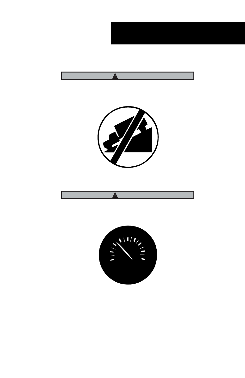
Do NOT use the wheel differential lock when traveling downhill.
WARNING
Do NOT use the wheel differential lock at speeds over 25 MPH.
40
30
20
10
0
50
60
70
80
MPH
1
Page 4
Warnings & Cautions
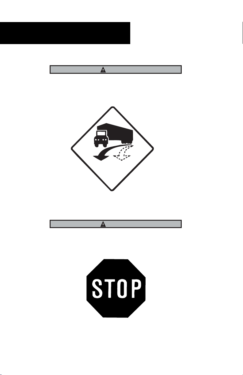
WARNING
When the wheel differential lock is engaged, be sure to allow for a larger turning radius and greater steering effort.
ACTUAL
PATH
DESIRED
PATH
WARNING
Engage the wheel differential lock ONLY when the vehicle is stationary or
moving without wheel differentiation (spinout).
2
Page 5

Overview
Operation Overview
Dana's wheel differential lock is driver-controlled and operated by the carrier
mounted air-actuated shift unit. In operation, it positively locks the wheel differential to provide improved traction under adverse road conditions. The differential lock is controlled through an electric switch or air valve mounted in
the cab. The locking mechanism is air operated to engage a mechanical clutch
that locks the wheel differential. It is spring operated to disengage the lock and
permit the wheel differential to operate normally.
Air pressure applied to the shift cylinder moves the piston, push rod, shift fork
and sliding clutch engages the fixed clutch mounted or machined into the
wheel differential case half. The sliding clutch is splined to the axle shaft.
Engaging the two clutches locks the axle shaft to the differential case half,
which, in turn locks the wheel differential.
Disengaged Position
Note: Zero air pressure to shift system, the spring is keeping shift assembly in
disengaged position. Sliding clutch is splined to the axle shaft.
3
Page 6

Overview
Engaged Position
Note: Vehicle system air pressure is now applied to the shift system. Sliding
clutch now connects the axle shaft to the differential case. Wheel differential can not rotate. Both wheels will turn at the same speed.
4
Page 7

Overview
Control Systems for Wheel Differential Lock
Two systems may be used to control the wheel differential lock operation.
Direct Interlock System
The driver manually locks and unlocks the wheel differential using a cabmounted control valve or switch. When the control switch is placed in the lock
position, the air supply solenoid valve opens and air pressure activates the
shift unit. When the control switch is placed in the unlock position, air pressure supply is shut off and air pressure is released from the shift unit.
Note: Vehicles with this system should not be operated with the wheel differ-
ential engaged above 25 MPH.
In-Cab Switch
or Valve
Vehicle System Pressure 80 - 120 PSI
5
Page 8

Overview
Transmission Low-Range Interlock System
The wheel differential is locked manually with the transmission in Low-Range.
It is unlocked by the driver or unlocked when the transmission is shifted out of
Low-Range. It is designed to ensure the differential lock is not left engaged at
speeds above 25 mph.
When the driver places the cab mounted control valve in the lock position and
with the assist pressure from the transmission control circuit, tank air pressure is supplied to the differential lock shift unit through the cab mounted
control valve.
Note: If the transmission is shifted out of low range (with cab mounted con-
trol valve in the lock position), the air pressure to the differential shift
units is shut off automatically. The transmission Low-Range valve
closes, shutting off air assist supply to the cab mounted control valve
which, in turn, releases the tank air pressure from the air shift unit. If the
driver subsequently shifts back into Low-Range, the differential lock will
not re-engage automatically.
In-Cab Switch
or Valve
Transmission Low-Range
6
Page 9

Operation
Operating Instructions
Engage (Lock)
1. Flip the control valve lever to the " Lock" position, either while the
vehicle is stationary, or while moving at steady speed under 25 MPH
without the wheel differentiation (spinout).
2. Let up momentarily on the accelerator pedal to relieve torque on the
gearing and fully engage the sliding clutch.
3. When the differential lock is engaged, the indicator light will be on, or
an audible signal will sound.
Note: When the differential lock is engaged, the vehicle will under-steer,
requiring a longer turning radius for a given turn.
Disengage (Unlock)
1. To disengage the wheel differential lock, flip the control lever to the
"Unlock" position.
2. Let up on the accelerator pedal momentarily to relieve torque and
allow the sliding clutch to disengage.
3. When the differential lock is disengaged, the indicator light and/or
audible sign will go out.
Note: Occasionally the differential lock may not disengage immediately due to
torque “wrap up,” when this occurs, drive normally for a short distance
with the control level still in the "Unlock" position until normal road
forces release the torque wrap up condition.
7
Page 10

Operation
Important To Remember
When engaged, the wheel differential lock will cause the vehicle to understeer, meaning that the vehicle will not turn as quickly, and more steering
effort will be required.
Do not use the wheel differential lock when traveling downhill. This will ensure
maximum control of the vehicle.
Use the wheel differential lock only at speeds less than 25 MPH. At higher
speeds the under-steer handling characteristics could be dangerous.
The differential lock should only be engaged when the vehicle is stationary
(recommended), or moving less than 25 MPH without wheel differentiation
(spinout). Engagement of the wheel differential lock while wheels are rotating
at different speeds (differentiation) may cause shift fork scoring and bending,
clutch teeth to fail and/or axle shaft shock failures.
This system should only be used when poor traction is encountered; it must
be disengaged when traveling on solid road surfaces.
Operating the wheel differential lock in the engaged "lock" position of sold surfaces while turning corners (differentiating), may cause clutch jump out damaging shift system components.
The wheel differential lock may not disengage immediately due to torque
"wrap up". This wrap up can occur when the system is disengaged while the
vehicle is operating on surfaces such as sand, mud or even snow.
8
Page 11

Page 12

Copyright Dana Limited, 2009. Dana
hereby grants their customers, vendors, or
distributors permission to freely copy,
reproduce and/or distribute this document
in printed format. It may be copied only in its
entirety without any changes or modifications.
THIS INFORMATION IS NOT INTENDED
FOR SALE OR RESALE, AND THIS NOTICE
MUST REMAIN ON ALL COPIES.
©2009 Dana Limited
All rights reserved. Printed in USA
For spec’ing or service assistance, call 1-800-ÈÓ£-nän{ or visit our web site
at www.ëViÀ«>ÀÌÃ.com.
Spicer: Dana and other trusted partners providing the best
products and services in the industry, ensuring more time on the road.
 Loading...