

Page 1

Conductivity, TDS,
Salinity Meter
850038
Instruction Manual
SPER
SCIENTIFIC
Page 2

INDEX
Introduction..............................................1
MaterialSupplied....................................1
Ports&Probe ............................................1
Specifications .........................................2
LCDDisplay ..................................................2
KeypadOperation ........................................4
Auto Shut Off .................................. 6
RecallMode ..............................................7
ReviewMode.................................................7
Peparation For Calibration.............. 8
ConductivityCalibration .........................11
TDS Calibration.......................................14
SaltCalibration .......................................16
ConductivityMeasurement....................18
TDS Measurement ................................20
SalinityMeasurement.............................21
ParametersSetting.................................23
Maintenance& Storage..........................35
Trouble Shooting..................................... 36
Warranty ......................................................... 37
IrDATransmission..................................38
RS232Output ........................................39
AppendixA..............................................40
AppendixB .............................................41
AppendixC..............................................41
AppendixD..............................................42
Page 3
INTRODUCTION
This meter measures conductivity value
in uS and mS, as well as total dissolved
solids (TDS) and Salinity. Simultaneously
displays readings, time, date, and temperature in °C or °F.
Features a detachable probe, ATC, 99
memory points, min-max-average, hold,
RS232 port, large LCD, auto shut off, and
indicators for low battery and over range.
MATERIAL SUPPLIED
This package contains:
Meter
Probe
Batteries AAA x 4pcs
Instruction manual
Hard carrying case
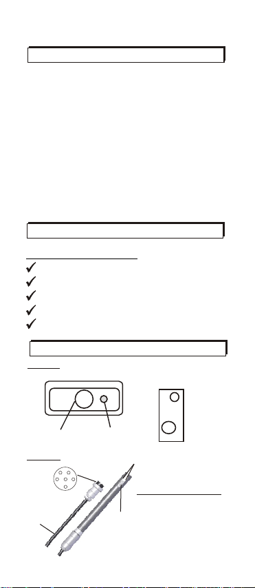
Meter
PORTS & PROBE
Top view
Conductivity probe
connector port
Probe
Connector
to meter
~ 87 cm
Right side view
IrDA port
3x10mm sensing
area on each side
Standard probe
*ABS body, graphite cell.
*Highest durability with
Temp.
reliable measurements.
sensor
*Integral temperature.
inside
*Temperature steady
time <10 seconds.
1
DC 9V
RS232
Page 4
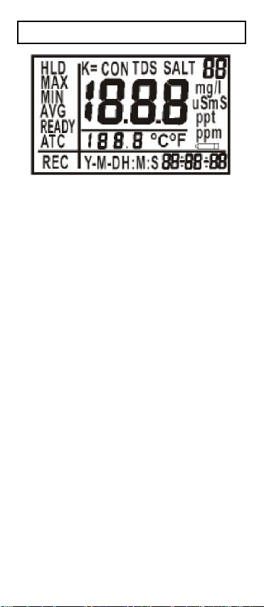
DISPLAY
Themeterwill briefly displayall
LCDsegmentswhen it is first
turnedon.
The primary display shows:
Themeasuredconductivityvalue
(CON) in uS or mS per cm.
TDS in ppm or ppt
Salinity in ppt
The secondary display below
the primary display shows:
The temperature of the reading.
Year/Month/Date and
Hour/Min/Sec (displayed
at the bottom of the screen).
HLD(Hold),Max,Min,Avg,
ReadyandATC are shownon
theleftside of the screen.
REC (Recall)isshownatthe left
bottom left.
The top right number ("88")
indicates the records in
memory.
3
Page 5
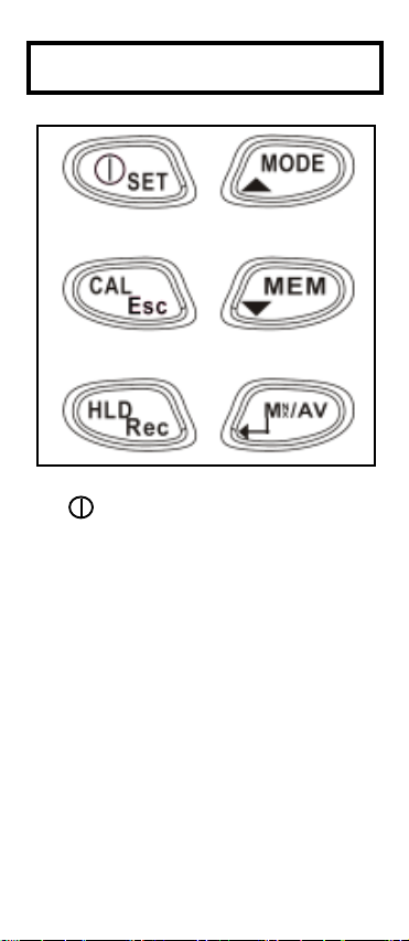
KEYPAD OPERATION
1. SET (Power) key:
Turn on the meter by pressing
the SET key. The entire display
flashes. Once the m,eter is on,
press this key for more than 2
seconds to enter the
settings m,ode.
Manually turn the meter off by
pressing and releasing this key.
2. ▲ MODE key:
Press the Mode key to switch
between the displayed
measurements for conductivity
(CON), TDS, or Salinity (SALT).
4
Page 6

3. CAL/Esc key:
ATC
CON
H:M:SouS
ATC
Y.M.D
CON
o
uS
In normal mode, press this key > 2
seconds to enter calibration mode.
While the meter is in calibration, setting
or recall mode, press this key (Esc) to
return to previous mode.
4. MEM :
In normal mode, press this key to store
the current reading with RTC (real time
clock), the primary display will flash 3
times. The occupied memory number
(88 on the top right corner) changes
from xx to yy, eg: 00 to 01 .(Fig. A& B)
In setting mode, press this key to
change the setting content. Under
recall mode, press this key to read
memories.
C
Fig.A Fig.B
5-1.HLD/REC :
In normal mode, press the key < 1 sec.
To hold the current reading, then
quickly press the key again to unlock
it. In normal mode, press the key
more than 2 seconds to enter recall
mode. (Fig. C, page 6)
5
Page 7

Press HLD+ENTER for the backlight.
The backlight will turn off automatically
after 10 seconds.
CON
uS
Fig. C
REC
Y-M-D
o
C
6-1.
MI/MX/AV key:
In normal and recall mode, press this
key to view Max./Min./Avg. readings.
In normal mode, press key > 2 sec. to
clear the value. The entire LCD will
flash for 2 seconds.
In setting mode, press this key to
enter content setting.
7. SET + :
When the meter is off, pressing these
two keys simultaneously for more than
one second disables auto-off mode.
AUTO POWER OFF
The meter will auto-powered off in
20 minutes after last key press.
This function saves battery power.
To override this function, press POWER
and UP keys at the same time until "n"
is displayed. Release the keys and
meter will enter
normal mode.
6
Page 8

RECALL MODE
In the normal mode, press more
HLDHLD
RecRec
than 2 seconds to enter RECALL (REC)
mode. Press MIN/MAX/AV to view
Maximum, Minimum and Average of the
memorized data ( Fig. D). You
could also press or to review
MODEMODE
MEMMEM
the memories one by one.
"REC" is flashing in recall mode. To exit
recall mode, press more than 2 sec.
Quickly press to return to normal
mode. LCD will show the last memory
CALCAL
Es cEs c
HLDHLD
RecRec
count saved before you entered recall
mode.
CON
MIN
REC
uS
o
C
Fig. D
Press MX/MN/AV key w
hen REC is
flashing, so that the MAX value of the
all memories will diaplay. Press
MX/MN/AV key again to view MIN.
Press again to view Average. The top
right corner record number will not be
displayed while viewing MX/MN/AV.
REVIEW MODE
NN
/AV/AV
XX
In normal mode, press key < 1sec.
MM
to view MAX, MIN, AVG. These values
are cleared when the meter is turned off.
You can press the key > 2 second
NN
/AV/AV
XX
MM
to clear these values (LCD will flash for
2 seconds). Note: Clear the values when
the measurement is stable.
7
Page 9

PREPARATION FOR CALIBRATION
Two issues should be considered
before operation:
What is the right calibration standard?
When should you calibrate?
Selecting a calibration standard
For best results, select a conductivity,
TDS or NaCl standard near the
sample value you are measuring.
Alternatively, use a calibration solution
value which is approximately 2/3 of the
full scale of the measurement range you
plan to use.
For example, in the 0 to 1999 uS range,
use 1413 uS solution for calibration.
DO NOT reuse the calibration solution.
Contaminants in the solution will affect
the calibration and the accuracy. Be
sure to use fresh solution each time.
Refer to below table.
Use the recommended solution for
different conductivity and TDS ranges
for best results.
Conductivity
measuring range
0~19.99uS
1
0~199.9uS
2
0~1999uS
3
4
0~19.99mS
0~199.9mS
5
Recommended cal.
solution range
6.00~17.00uS
60.0~170.0uS
600~1700uS
6.00~17.00mS
60.0~170.0mS
TDS measuring
range (factor=0.5)
0.00~9.99ppm
1
0.0~99.9ppm
2
0~999ppm
3
0.00~9.99ppt
4
0.0~199.9ppt
5
Recommended cal.
solution range
3.00~8.50ppm
30.0~85.0ppm
300~850ppm
3.00~8.50ppt
30.0~85.0ppt
8
Page 10
This meter has a built-in algorithm
to linearize the measurement of
Sodium Chloride concentration.
For SALT calibration, you only need
to perform one-point calibration.
The previous calibration data will be
replaced after re-calibrating. For
example, if you previously calibrated the
conductivity meter at 1413 uS in the 0
to 1999 uS range, when you re-calibrate
it at 1500 uS again (also in the 0 to
1999uS range), the previous 1413uS
will be replaced in this range (0~1999uS).
However, the meter will retain the
calibration data for other ranges which
are not yet re-calibrated.
If you use solution to calibrate one range
and then manually input the cell constant
(P5.2), the cell constant of range 1
to 5 will be changed simultaneously.
.
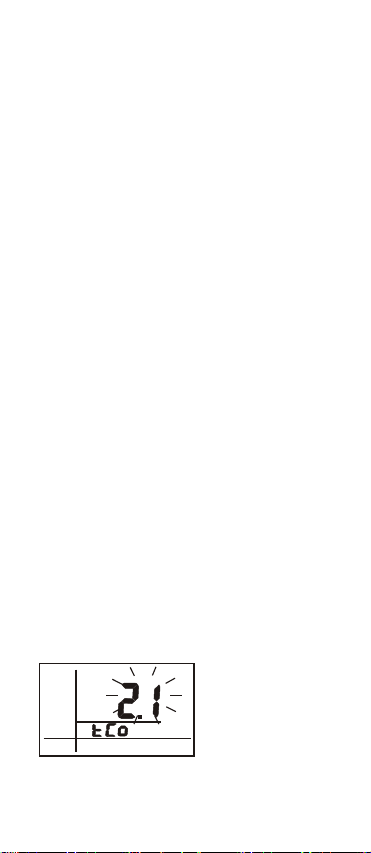
NOTE:
The temperature coefficient of the meter
defaults to 2.1% per C (Fig. E) and
o
provides good results for most
applications. See Program P4.1
on page 27 to reset the coefficient.
Alternatively, refer to Appendix D to
calculate the temperature coefficient
and determine the appropriate
temperature coefficient for solution.
o
C
Fig. E
NOTE:
The default normalization temperature
value is 25°C.
9
Page 11
To normalize to another value, see
K=0.966
P4.2 on page 28 (Fig. F). Before
resetting this value,
the calibration
standard value of the normalized temp.
must be known. (Refer to the datasheet
enclosed with
your solution.)
o
C
Fig .F
When should you do the calibration?
For first useand for best results,
use solution to calibrate or
manually input the cell constant
if
solution is not readily available.
(refer to the label on the probe).
NOTE: The cell constant has
been programmed into meter.
To completely calibrate the meter,
clear all previous calibration data,
(to erase all calibration data,
see P7.1 on page 32 (Fig. G)).
K=
0.966
Fig .G (8306)
Cell Constant
If the conductivity of measured solutions
are < 100 S, or TDS are < 50 ppm,
calibrate the meter at least once
a week for accuracy.
If the meter is used in the mid ranges,
it is needed to do calibration at least
once a month.
If the measurement is performed at
extreme temperatures, calibrate at
least once a week.
10
Page 12
CONDUCTIVITY CALIBRATION
Follow the below steps for
conductivity calibration:
Insert the probe into demineralized
1.
water or distilled water for about 30
minutes to rinse the probe.
Select the conductivity standard for
2.
calibration. ( See page 8)
Pour 4 cm (deep) of the solution into
3.
two separate clean containers(A&B).
Turn on the meter, the entire display
4.
flashes three times and then returns
to the normal measurement mode.
5.Rinse the probe in one of the
containers. Gently stir the probe.
6.Dip the rinsed probe into the other
container. Tap the probe on the bottom
of container to remove air bubbles.
Let the probe stabilize to the solution
temperature.
66
K=0.966
K=0.9
4cm
A(Step 5)
4cm
B( Step 6)
7.Press CAL key more than2 seconds to
enter calibration mode. The probe
auomatically detects the conductivity
value of solution and blinks the value
on the LCD (Fig. H)
CON
uS
READY
H:M:S
o
C
Fig .H
11
Page 13

8. Press the UP/DOWN keys to change
the value on the primary display to
match the value to the standard
( normalization temp. is 25°C).
Adjust the conductivity reading
up to +20% from the detected
value. However, if the detected value
and standard value differ by more
than +20%, clean or replace the
probe.
Example:
Standard: 10uS; Detected value:19uS
Adjustable range: +3.8us (19*20%)
However, under above situation, the
values already differed over 20%.
NOTE:
* When the calibration is stable,
"Ready" will display. If not,
check that the calibration solutions
aand the input value (step 8) are
correct.
* Cell constant may degrade with time
and usage. Use this feature
as a reminder for changing to a new
probe.
* The meter will automatically detect
the solution, If the standard value is
over the measuring limit or less than
10% of measuring
value will equal the range limit or
10% of range limit. Under this situation,
go to parameter settings first to
manually select a suitable
range. (P1.0, see page 23).
Example 1:
Standard: 22uS; Detected value:19uS
Adjustable range: +3.8us (19*20%)
Although the values differ less than
limit, the displayed
12
Page 14

20% but the 22uS is already over
range limit so the maximum value
could be input is 19.99uS only.
To exactly adjust the value to 22uS,
please manual select the range as
0~199.9 in P1.3
Example 2:
Standard: 1.6uS; Detected value:2.1uS
Adjustable range: +0.42us (2.1*20%)
Although the values differ less than
20% but the 1.6uS is already less than
10% range limit (1.99) so the max.
value that could be input is 1.99uS.
9.After "Ready" is displayed, press
"ENTER" to confirm the calibration.
The LCD will stop flashing and the
meter will switch back to normal
measurement mode.
10.Repeat 1~9 for other ranges.
NOTE:
* When switching the meter from
measurment to calibration mode, the
meter will auto defect the solution
value based on the previously selected
cell constant (0.1,1.0 or 10), so,
sometimes the primary display
may seem to jump to the auto defected
value after entering calibration. This
means that even in the same solution,
it is normal for the displayed values
in measurment and calibration mode s
to be different.
* To exit conductivity calibration mode
without confirming calibration, DO
NOT press the ENTER key in step 9.
Press Esc to retain the meter's
previous calibration data for the
current range.
13
Page 15

TDS CALIBRATION
There are 2 options for TDS calibration
Option1: Using TDS standards
Follow these calibration steps:
1.
Insert the probe into demineralized
or distilled water for about 30 minutes
in order to rinse the probe.
Select the TDS standard for calibration.
2.
The factory default setting of the TDS
conversion factor is 0.50. If your
solution has a different TDS factor,
you can improve the calibration
accuracy by setting the TDS factor
before starting the calibration.
To change the TDS factors to the
correct value, see Appendix B
or refer to the value provided by
standard solution manufacturer.
3.
Pour 4 cm (deep) of the solution into
two separate & clean containers.(A&B)
4. Turn
on the meter. The full LCD will
flash three times. Press the
MODE key to select TDS mode.
5. Rinse the probe in one of the
containers. Gently stir the probe.
6. Dip the rinsed probe into the other
container. Tap the probe on the bottom
of container to remove air bubbles.
Let the probe stabilize to the solution
temperature.
66
66
0.9
K=
K=0.9
A(Step 5)
4cm
4cm
B( Step 6)
14
Page 16

7. Press CAL key for more than 2 sec.
To begin the calibration. The TDS
value blink on the display. (Fig. I)
8. Press the UP/DOWN keys to match
the value on the primary display to
the value of the standard
solution. Refer to the solution
normalization temperature.
The meter is defaults to 25°C.
TDS
READY
H:M:S
NOTE: Refer to the notes on pages
12 & 13
9. After " Ready" displays, press
Ppm
o
C
Fig .I
"ENTER" to confirm the calibration.
The LCD will stop flashing and the
meter will switch back to TDS
measurement mode.
10. Repeat 1~9 for other ranges asneeded.
Option2: Using Conversion Factors
TDS values are related to conductivity.
You can calibrate the meter by using
conductivity standards as described
above and then program the meter with
a given conversion factor. Refer
to below steps:
1. Perform the conductivity calibration
procedure on page 11~13.
2. Select the correct Conductivity-to TDS conversion factor. Refer
to Appendix B or calculate the TDS
conversion factor for other solutions
using the formula show in Appendix C
3. Refer to P2.1 (in page 25) to check
the settings procedures.
15
Page 17

SALT CALIBRATION
Follow the below steps for salinity
calibration:
1. Insert the probe into demineralized
or distilled water for about 30 minutes
to rinse the probe.
2. Select the Sodium Chloride standard
for calibration. 10~40ppt is suggested.
3. Pour 4 cm (deep) of the standard into
two separate & clean containers.(A&B)
4. Turn on the meter. The full LCD will
flash three times. Press the MODE
key to switch to SALT mode.
5.Rinse the probe in one of the contai ners. Gently stir the probe. Rinsing
removes contaminants that affect
the calibration.
6. Dip the rinsed probe into the other
container. Tap the probe at bottom of
container to remove air bubbles. Let
the probe stabilize to the solution
temperature.
0.966
66
0.9
K=
K=
4cm
A(Step 5)
4cm
B( Step 6)
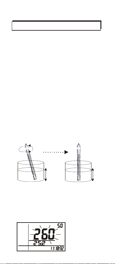
7. Press CAL >2 sec. to begin the
calibration. The SALT value will blink
on the LCD.( Fig. J)
SALT
READY
ATC
H:M:S
ppt
o
C
Fig .J
16
Page 18

8.Press the UP/DOWN keys to match
the value on the primary display to
the value of the calibration standard.
Adjust the SALT reading up
to +20% from the detected value. If
the detected value and standard
values differs by more than +20%,
clean or replace probe
The maximum input value is 50 ppt
and the minimum input value is 1ppt.
9. When "Ready displays, press
"ENTER" to confirm the calibration.
The meter switches to SALT
measurement mode. Note:For high
accuracy in Conductivity &TDS
modes, perform the calibration
again before measuring Conductivity
or TDS if ou have performed a
salt calibration.
17
Page 19

CONDUCTIVITY MEASUREMENT
Range Selection ( For COND. & TDS)
The meter defaults to "auto-ranging"
mode. Auto-ranging selects the
range that gives you the greatest
resolution and accuracy.
Alternatively, you can manually select
one of the five ranges in setup mode
P1.0 (see page 23).
Example: If you prefer the meter to
display a reading as 0.50 mS rather than
500 uS, you could select the "0 to 19.99
mS" range by the manual ranging function.
The meter will reset to auto-ranging
mode once it is turned off.
NOTE:
Accuracy is a percent of full-scale, so
using your meter in the lowest range
will provide the greatest accuracy.
Automatic Temperature Compensation
(For COND. & TDS)
To measure with automatic temperature
compensation, follow the below
steps:
1. Turn on the meter. "ATC" should
be displayed on the left -bottom
corner of the LCD. If the ATC indicator
doesn't appear, the manual
temperature compensation is
selected.
See P2.4 on page 26 for instructions
on selecting Automatic Temperature
Compensation.
2. Set the temperature coefficient to
the correct value.
18
Page 20

The meter defaults to 2.1%
per C ( temperature coefficient).
This provides good results for most
applications. You may see P4.1 on
page 27 to set the temperature
coefficient to a different value.
3.Select the normalization temperature.
The meter defaults to 25°C
(normalization temperature).
To reset the value, see
P4.2 on page 28.
4.Press Esc to switch back to normal
mode. Rinse the probe with deionized
or distilled water before using to
remove any impurities adhering to
the electrode body.
If the electrode isn't used for a long
time, soak the probe for at least
30 mins.
5. Dip the probe into the sample. Make
sure there are no air bubbles trapped
on the slot of the probe. To remove
air bubbles, stir and
make sure the electrode tip is
submerged.
6.Stir the probe gently in the sample to
create a homogenous sample. Allow
a few seconds for the temperature
reading to reach the solution
temperature.
the probe mildly
7. Take readings. When the reading is
stable, "READY" will be displayed on
the left-middle LCD.
19
Page 21

Manual Temperature Compensation
(For COND. & TDS)
To measure with manual temperature
compensation, follow the below
steps:
1. Turn on the meter. Press the set key
more than one second to enter setting
mode.
Refer to P2.4 (page 26)
to disable the ATC function.
2. To set a manual temperature
compensation value. See
P4.3 on page 29.
3. To switch the meter back to normal
mode. The middle region of LCD will
display a fixed temperature that you
input, "ATC" is not displayed.
To start the measurement
follow steps 4-6 on page 19.
NOTE:
Manual Temperature Compensation
only available when the ATC
is off. For non-compensated
measurements, change the temp.
coefficient to 0.0%.( Fig. K)
o
C
Fig. K
TDS MEASUREMENT
Follow the below steps for TDS
measurement.
1. Turn on the meter.
2. Set the TDS conversion factor to a
correct value. The factory default
value is 0.50. Refer to P2.1 on page
25.
20
Page 22

To chang the TDS factor to another
value, see Appendix B &C on page 41.
3. Select Range, automatic temperature
compensation or manual temperature
compensation per your application
by following steps on page18~20.
4.Start to take readings. Press "MODE"
to switch the meter to TDS mode.
(Fig. L)
TDS
READY
ATC
H:M:S
ppm
o
C
Fig. L
SALINITY MEASUREMENT
In SALT mode, the following fixed
conditions apply:
*Built-in NaCL conductivity to TDS
conversion factor.
*Temp. Coefficient.
*Normalization Temp. (fixed at 25 C)
o
1. Taking measurements with READY
indicator activated:
If the READY indicator is activated,
"READY" is displayed when the
reading is stable. (Fig. M) .
To turn the READY indicator on or off
See P 2.2, page 25.
SALT
READY
ATC
H:M:S
ppt
o
C
Fig.M
21
Page 23

2.Taking measurements with the auto
endpoint feature activated:
2.
When a reading is stable for more
than 5 seconds, this feature will
automatically hold the reading in the
display. "HLD" appears on the top-left
of the LCD. Press the HOLD key to
unfreeze the reading (Fig. N)
HLD
READY
ATC
H:M:S
SALT
o
C
ppt
Fig.N
To turn the Auto endpoint feature on
or off see P 2.3 on page 26.
22
Page 24

PARAMETER SETTING
1. When the meter is in the normal mode,
press for more than two seconds
to enter to setup mode.
2. Press to switch the setting
parameter one by one.
3. Press ESC key to return to the previous
status.
4. Press ENTER to enter each parameter
setting as follows:
a) P0.0: Print (Prn)
At P0.0, press ENTER to reach P0.1.
"Prn" will flash to indicate that the meter
is transmitting the memories through
its IrDA port to another device. ( Fig. O)
b) P1.0: manual range setting (rAn)
Normally, the meter will automatically
select a range when readings appear.
The manual ranging function allows
you to select a specific range and
and corresponding resolution.
This function is for COND and TDS
measurement. The Salinity range is
fixed. There are 5 ranges.
SET
or
IrDA port to port should be at
less than 30 degree angle.
Fig. O
Press the UP or KEYS to select
the ranging function, rAn. (Fig.P ).
When you see P1.0, press ENTER.
23
Page 25

The digits flash on the display.
CON
uS
Press the UP or DOWN key to select
Fig. P
from P1.1 to P1.5 and then press
ENTER to save.
NOTE: Press ENTER to select
P1.1or other ranges, LCD will flash
the limit value (Fig. P). Press the
ENTER key to confirm. The meter will
return to normal measure mode.
The LCD will display E03 if the
measured conductivity/TDS values
are beyond the limit value.
Select a range within limits.
The meter will reset to the Autoranging function when it is turned off.
The manual ranging function must be
set each time the meter is turned on.
Range
P1.1
P1.2
P1.3
P1.4
P1.5
Type
Ist Range
2nd Range
3rd Range
4th Range
5th Range
Cell Constant
=0.1
0~1.99uS/ppm
0~19.99uS/ppm
0~199.9uS/ppm
0~1999uS/ppm
0~19.99mS/ppt
Cell Constant
=1.0
0~19.99uS/ppm
0~199.9uS/ppm
0~1999uS/ppm
0~19.99mS/ppt
0~199.9mS/ppt
Cell Constant
=10
0~199.9uS/ppm
0~1999uS/ppm
0~19.99mS/ppt
0~199.9mS/ppt
0~1999mS/ppt
24
Page 26

c)P2.0: Meter configuration: (CoF)
P2.1: TDS factor: (tdS)
The concentration of dissolved salts
in solution increases the conductivity.
This effect varies from salt to salt and
is roughly linear in a given range for
a given salt. The TDS conversion
factor is a value used by the meter
to convert from conductivity to TDS.
After selecting P2.0, press ENTER
to select P2.1. Press again to enter
P2.1. TDS factor flashes on the LCD
(Fig. Q). You can press UP/DOWN
to change the value from 0.40 to 1.00.
The default value is 0.50.Press
ENTER to confirm
the TDS factor and
select P2.2
automatically.
Fig. Q
P2.2: READY indicator:(rdy)
Turn the READY indicator
"on" to alert you that the measurement
is stable.
Select "off" for faster response.
Press UP/DOWN to switch the
ready function to "on" or "off". (Fig. R)
Press ENTER to confirm the last state
and select P2.3 automatically.
Fig. R
25
Page 27

P2.3: Auto endpoint function:(AEP)
P2.3 lets you switch on or off the
"Auto endpoint function". Select auto
endpoint "on" to HOLD your
measurement when it is stable for
more than 5 seconds. The display
value will freeze and the HLD indicator
will appear on the LCD. Press the
HLD key again to release the display.
Select the auto endpoint "off" to
deactivate this feature.
UP/DOWN to switch
function on or off (Fig. S). Press
ENTER to confirm the last state and
select P2.4 automatically.
Fig. S
P2.4: ATC or non-ATC: (Atc)
P2.4 allows you to select Automatic
or Manual Temperature Compensation.
The default is ATC.
Press UP/DOWN to switch a
temperature compensation on or off
(Fig. T).
Press ENTER to confirm the last state
and return to P2.0.
NOTE:
The default is "Ready Indicator on",
"auto endpoint function off" &
"ATC on"
Press
auto endpoint
utomatic
Fig. T
26
Page 28

d) P3.0:Unit :(Unt)
P3.1 selecting C or F:(t)
Select P3.0 and press ENTER to
advance to P3.1.
Press UP or DOWN key to switch C
o
or F. Press ENTER again to confirm
the last unit and advance to P3.2
automatically. (Fig. U)
o
F
C
Fig U
P3.2 selecting ppm or mg/L: (tdS)
After entering P3.2 from P3.1, the TDS
unit(mg/l or ppm) will flash on the LCD.
The default unit is ppm.
Press UP or DOWN key to switch ppm
or mg/l, Press ENTER again to confirm
the last unit and return to P3.0.(Fig. V)
ppm
o
mg/l
e)P4.0: temperature parameters: (t)
Fig V
P4.1: Temperature coefficient:(tCo)
The temp. coefficient (
percent per C)
conductivity
of per degree of temp.
o
expressed as
is the changed ratio
By using a suitable temp. coefficient
the meter will accurately compensate
the temperature for most solutions.
The adjustable range is 0.0 to
10.0 % per . The default is 2.1%
o
per . Note: 0.0% has no effect on
o
C
C
o
per C
temperature and the displayed value
is the same as actual temperature.
27
Page 29

Select P4.0 and press ENTER to
advance to P4.1. Press ENTER again
and the Temperature Coefficient will
flash. Press UP/DOWN to change
the value from 0.0 to 10.0, the unit is
o
%/ C (Fig. W). Press ENTER to
confirm the last value and advance to
P4.2 automatically.
o
C
Fig W
P4.2: Normalization temperature:(nor)
The meter will normalize its cond.
measurement to a standard temp.
which you preset.
Adjust the normalization temperature
from 15 to 30 C (59 to 86 F).
The meter default is 25 C (77 F).
oo
oo
After pressing ENTER, the normali-
zation temperature will flash on the
LCD. Press UP/DOWN to change the
value from 15.0 to 30.0 C (59.0~
o
86.0 F). (Fig. X)
o
Press ENTER to confirm the last
value and advance to P4.3.
o
C
Fig X
NOTE: To know more about the
temperature effect on on measurement,
refer to Appendix D on page 43
28
Page 30

P4.3: Manual temp. Compensation:(Int)
When you disable the ATC and select
manual temperature compensation,
you need to manually enter the temp.
value of solution into the meter. You
can select any temperature between
0 and 50 C (32 to 212 F). The default
is 25 C (77 F).
Press ENTER to move to P4.3 from P4.2,
the default manual input temperature
will flash on the LCD.
Press UP to select the flashing value
from 0~9.( Fig. Y)
Press DOWN to select the digit.
Adjustable range is from 0.0~50.0 C
(32.0~122.0 F). The default is 25.0 C
(77.0 F).
Press ENTER to confirm the last
input and return to P4.0.
o
C
f)P5.0: CELL setting: (CEL)
Fig Y
P5.1: Cell Constant:(SEL)
.
The cell constant, K, 1.0, 10,
or 0.1.
Use Cell Constant 1.0 for
midrange measurements.
Use Cell Constant 10 for high
range measurements (above 20 mS
or 10 ppt)
Use Cell Constant 0.1 for low
range measurements (below 20 S
or 10 ppm)
Using the correct cell constant is
important to obtain the optimal reading
in various ranges of measurement.
Refer to following table ranges.
29
Page 31

Ranges available
COND./TDS (Factor=0.5)
0.00~19.99uS/0~9.99ppm
0.0~199.9uS/0~99.9ppm
0~1999uS/0~999ppm
0.00~19.99mS/0~9.99ppt
0.0~199.9mS/0.0~99.9ppt
K=0.1 K=1.0 K=10
*
*
*
*
*
*
*
*
*
NOTE: The cell constant of the probe
sold with this meter is near K=1.0.
K=
Fig Z
Select P5.0 and press ENTER to
advance to P5.1. Press ENTER again
and the cell constant value will flash.
Press UP/DOWN to switch the
value from 0.1,1.0,10.0, one by one.
The default value is 1.0. (Fig. Z)
Press ENTER to confirm the last
input and select P5.2 automatically.
NOTE:
When using a cell constant K = 0.1,
the measured range will be only 1/10
of the range measured by K=1.
So, the lowest range will be 0~1.99us
(0~0.99ppm). Since only 5 ranges
are available, the highest range will
only be 0~19.99mS (0~9.99ppt).
When using a cell constant K = 10,
.
the measured range will be 10 times
the range measured by K=1.
So, the highest range will be: 0 to
1999 mS (0.0 to 999 ppt). Since
only 5 ranges are available, the lowest
range will be 0 to 199.9uS (10.0 to
99.9 ppm)
30
Page 32

P5.2: Input the cell constant:(InPt)
If constant K=0.1/1/10 does not
completely meet your needs,
input the cell constant after selecting
the K=0.1, 1 or 10.
For example: K=0.992
After saving P5.1, P5.2 will be
selected. Press ENTER again to
advance to P5.2.The cell constant r
(0.1, 1 or 10) will flash on the LCD.
Press UP to select the flashing value
from 0~9. ( Fig. AA)
Press DOWN to change the flashing
digit.
The selectable range is ell
20%of c
constant which is selected in P5.1.
Press ENTER to confirm the last
value and return to P5.0.
After inputting cell constant,
NOTE:
all calibration information in P8.0 will
be cleared. Manual input of the Cell
Constant will change all the constants
in ranges 1~5 at the same time.
K=
Fig. AA
g).P6.0: Memory Clear: (Clr)
P6.1: Memory clear(CLr)
Use this function to clear all stored
memory when you need to store a
new series of values. This function
lets you avoid confusing the old
values with the new ones.
In P6.0, press ENTER to enter P6.1.
Press UP/DOWN to select "n"-NO or
"y"-YES, then press ENTER to
confirm and the meter will return to
P6.0. (Fig. AB)
31
Page 33

If the memory is full, you must clear
all values to continue recording. If
not, when you record the 100th value,
"FuL" will flash 3 times.
.
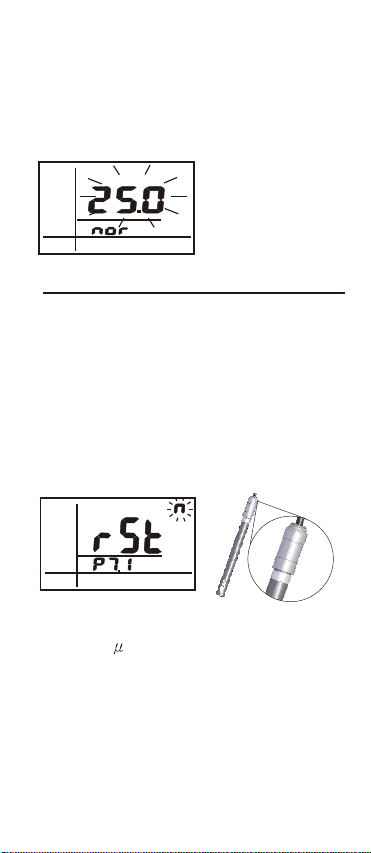
h)P7.0:Reset to factory default setting(rSt)
P7.1: Reset (rSt) restores the factory
default settings. This function clears
all calibration data and other user
defined parameters except the clock
settings and memory.
In P7.0, press ENTER to advance to
P7.1. Press UP/DOWN to select "n"-NOr
or "y"-YES. (Fig. AC)
Press ENTER to confirm and then
return to P7.0.
NOTE: Refer to
he default parameters or recalibrate.
t
When replacing a probe, clear all
calibration data in memory.
Appendix A to review
Fig. AC
i)P8.0:View calibration data (CAL)
Fig. AB
This function lets you recall previous
calibration data and may help you
know when its time to re-calibrate
the meter. This function is for
"Review" purpose only.
32
Page 34

In P8.0, press ENTER to advance to
P8.11. Press the UP/DOWN key to
change to P8.X. Ex:UP key to enter
P8.2 or DOWN key to return P8.0.
P8.1 is calibration data for range 1
P8.2 is for range 2, ...... P8.5 is for
range 5. (Fig. AD)
Calibration data and date
(Y-M-D HH:MM:SS) are displayed.
If there is no prior calibration data
at a particular range, the primary
display will show "---"
CON
mS
Y-M-D
Y-M-D
-
Fig. AD
J)P9.0:Electrode data:(ELE)
This mode has 5 parameters, P9.1
to P9.5 which display the probe cell
constantvalue for diagnostic purposes. Without calibration solution,
the cell constant value will be equal
to the value in P5.2 for 5 ranges.
Otherwise, the cell constant value
will be equal to the value set during
your calibration procedure.
.
In P9.0, press ENTER to advance to
P9.1. Press UP/DOWN key to change
to P9.X (P9.1~P9.5).Ex: UP key to
enter P9.2 or DOWN key to enter P9.0
(Fig. AE).P9.1 is the cell constant
value for range 1. P9.2 is for range 2,
etc.
33
-
Page 35

K=
k)PA.0:RTC Setting:(rtc)
Fig. AE
Press to PA.1,press
or
to set Year.
Press to PA.2,press
or
to set Month.
Press to PA.3,press
or
to set Day.
Press to PA.4,press
or
to set Hour.
Press to PA.5, press
or
to set Minute.
Press to PA.6,press
or
to set Second.
This procedure lets you set Y-M-D
first after every selection, press
to confirm the values. Next, digits will
be flashing until you press to
save. After setting Y-M-D, set the
H:M:S. The first digits will
flash until you press to confirm
(Fig.AF).
Y-M-D
Fig. AF
H:M:S
34
Page 36

±1% of full scale,
±1 digit
±0.05%
full scale
ppm: 0.01,
0.1, 1
ppt: 1.01, 0.1
0~1999
mS/cm: 0~19.99, 0~199.9
0~1999
ppt: 0.00~19.99, 0.0~199.9
Specs Range Resolution Accuracy
Conductivity µS/cm: 0~19.9, 0~199.9,
TDS ppm: 0.00~19.99, 0.0~199.9,
2
Salt ppt: 2~42 (KCL)
1°C >50°C
Temperature 0~80.0°C 0.1°C / 0.1°F 0.6°C <50°C,
Page 37

MAINTENANCE & STORAGE
a)Make sure the electrode is clean
Between measurements, rinse the
electrode with de-ionised water. If
the electrode has been exposed to a
solvent that is immiscible with water,
clean it with a solvent miscible with
water, e.g. Ethanol or acetone and
rinse carefully with water.
b)Store the conductivity cell carefully
Before storing the electrode, rinse it
carefully in de-ionised water.
Short-term storage: In de-ionised water.
Long-term storage: In de-ionised water
or store dry.
After long-term storage, leave the
electrode in de-ionised water for 8
hours before use.
c) Handle platinised cells carefully
Do not touch the black platinum layer
of the platinized cells.
To rinse the platinized cells,
dip the cell several times in a beaker
with demineralised water.
Be careful when rinsing platinized
cells with deionised water from a
water bottle. The force of the water can
remove some of the platinum layer
and consequently change the cell
constant.
35
Page 38

TROUBLESHOOTING
a) Power on but no display:
1) Make sure to press the power key
long enough to turn the meter on.
2) Check that the batteries are in place
and make sure ther is good contact and
matching polarity.
3) Replace all batteries.
4) Remove the batteries for one minute
and then reinstall them.
b) Display disappears:
Check whether the low battery
indicator is being displayed before the
LCD disappears, if so, replace the
batteries.
c) E01:
The probe is disconnected or damaged.
d) E02:
The measured value is below the
range limit.
e) E03:
The measured value is over the
range limit.
f) E04:
The value displayed in the primary LCD
is not correct. See E01~E03.
g)E32:
IC memory error.
h)E41:
Meter configuration error. For
example: the temperature coefficient
is over the setting limit.
36
ATC
H:M:S
CON
uS
o
C
Page 39

WARRANTY
Sper Scientific warrants this product
against defects in materials and
workmanship for a period of five (5)
years from the date of purchase, and
agrees to repair or replace any
defective unit without charge. If your
model has since been discontinued,
an equivalent Sper Scientific product
will be substituted if available. This
warranty does not cover probes,
batteries, or damage resulting from
accident, misuse, or abuse of the
product. To obtain warranty service,
ship the unit postage prepaid to:
SPER
SCIENTIFIC
7720 E. Redfield, Suite 7
Scottsdale, AZ 85260 USA
Th e def e c t iv e uni t m u s t be
accompanied by a description of the
problem and your return address.
Return your warranty registration card
within ten (10) days of purchase or
register online at:
www.sperscientific.com.
37
Page 40

IrDA TRANSMISSION
A maximum of 99 memories may
be transmitted via IrDA to an IrDA
receiver.
1. IR Protocol: Compatible with
SIR, 19200 bps, 8 data bits,
no parity.
2. The data format transmits every
second.
C***. **uS(mS):t***.*C(F):D***.
**ppm(ppt): S***. * ppt
@****-**-** **:**:**LRCCRLF
The error message format is:
ExxNul - "xx" is the error code
3. The format of the description
transmits every 15 records.
$CON:TEMP:TDS:SALTLRCCRLF
38
Page 41

RS232 OUTPUT: (9600 bps )
The meter can link with a PC to
capture on-line data and display
COND/TDS/SALT readings with
real-time output. You can
retrieve files, save the data for
data analysis, record statistics
and more.
Connection procedures:
Plug the optional RS232 cable
into the RS232 jack port (on
the right side of the meter)
Insert the D-sub 9P type
connector into computer's
Com. Port - OR-
Set up RS232 software by
inserting the CD-ROM.
When installing the RS232
software follow the procedures
in the operation manual.
T h e RS232 protocol is:
9600 bps, 8data bits, noparity.
The data format is:
Tx.ASCII code sent each
second while meter is on:
C***.**uS(mS):t***.*C(F):
D***.**ppm(ppt): S***.*ppt
@****-**-** **:**:**LRCCRLF
The error message format is:
ExxNul (xx is the error code).
Memory data is not available
via RS232.
39
Page 42

Appendix A: Meter Factory Default Setting
Type
P0.1
P1.1
P1.2
P1.3
P1.4
P1.5
P3.1
P3.2
P4.1
P4.2
P4.3
P5.1
P5.2
P6.1
P7.1
P8.1
P8.2
P8.3
P8.4
P8.5
P9.1
P9.2
P9.3
P9.4
P9.5
PA.1
PA.2
PA.3
PA.4
PA.5
PA.6
Parameters
IRDA
Output
Manual
range
setting
Select C/ F
Select ppm
or mg/L
Temp. coefficient
Nor. Temp
Manual compensation temp.
Cell const. Select
Cell const. Input
Clear Memory
Factory default
Viewing
previous
calibration
data
Viewing
probe data
Real time
clock. Only
8303, 8306
Default
OFF
OFF
OFF
OFF
OFF
C
ppm
2.1%/ C
25 C
25 C
1.0
1.0
NO Retain Memory
NO Retain your current
---
---
---
---
---
---
---
---
---
---
NO
Remark
The meter resets to
the Auto-ranging
function once it's
turned off
Temp unit
TDS unit (only 8302,
8305,8306)
Adjustable from 0.0 to 10%
Adjustable from 15 to 30 C
Adjustable from 0~50.0 C
Select K=1.0, 0.1 or 10
The input cell constant
offset is +20% of select
cell constant in
settings
No calibration data for 1st range
No calibration data for 2nd range
No calibration data for 3rd range
No calibration data for 4th range
No calibration data for 5th range
No offset for effective cell constant (1st range)
No offset for effective cell constant (2nd range)
No offset for effective cell constant (3rd range)
No offset for effective cell constant (4th range)
No offset for effective cell constant (5th range)
Retain year of current RTC.
Retain month of current RTC.
Retain day of current RTC.
Retain hour of current RTC.
Retain minute of current RTC.
Retain second of current RTC.
P5.1
40
Page 43

Appendix B: Conductivity to TDS
Conversion Factors
Conductivity
at 25 C
23 S 11.6 0.5043 10.7 0.4652 14.74 0.6409
84 S 40.38 0.4807 38.04 0.4529 50.5 0.6012
447 S 225.6 0.5047 215.5 0.4822 300 0.6712
1413 S 744.7 0.527 702.1 0.4969 1000 0.7078
1500 S 757.1 0.5047 737.1 0.4914 1050 0.7
2070 S 1045 0.5048 1041 0.5029 1500 0.7246
2764 S 1382 0.5 1414.8 0.5119 2062.7 0.7463
8974 S 5101 0.5685 4487 0.5 7608 0.8478
12,880 S 7447 0.5782 7230 0.5613 11,367 0.8825
15,000 S 8759 0.5839 8532 0.5688 13,455 0.897
80mS 52,168 0.6521 48,384 0.6048 79,688 0.9961
ppm value
TDS KCl
Factor
ppm value
TDS NaCl
Factor
TDS 442
ppm value
Factor
442: 40% sodium sulfate, 40% sodium
bicarbonate and 20% sodium chloride.
Appendix C: Calculating TDS
conversion factors
The meter can be calibrated by using TDS calibration
standard solutions. The calibration standard requires
the TDS value at a standard temperature such as
25 C. To determine the Conductivity-to-TDS
conversion factor, please use the following formula:
Factor = Actual TDS : Actual Conductivity @ 25C
Definitions:
Actual TDS: Value from the solution bottle label or
from a standard buffer which made by using high
purity water and precisely weighed salts.
Actual Conductivity: Value measured using a properly
calibrated Conductivity/TDS/Temperature meter.
Both the actual TDS and the actual conductivity
values must be in the same magnitude of units. For
example, if the TDS value is ppm, the conductivity
value must be in uS; if the TDS value is in ppt, the
conductivity value must be in mS.
Check this number by multiplying the conductivity
reading by the factor in the above formula and the
result is the TDS in ppm.
41
Page 44

Appendix D: Temperature Effect
Conductivity measurements are temperature
dependent, if the temperature increases, conductivity
increases. eg: the conductivity measured in a 0.01
M KCl solution at 20 C is 1.273 mS/cm, whereas, at
0
25 C, it is 1.409 mS/cm.
The concept of reference temperature (Normalization
temperature) was introduced to allow the comparison
of conductivity results obtained at different temperature.
The reference temperature is usually 20 C or 25 C.
The conductivity meter measures the actual COND.
and temperature and then converts it to the reference
temperature using a temperature correction function
and displays the conductivity at the reference temp..
It is mandatory to always associate the temperature
together with a conductivity result. If no temperature
correction is applied, the conductivity is the value
taken at measurement temperature. The 830x meter
used linear temperature correction.
Linear temperature correction:
In moderately and highly conductive solutions,
temperature correction can be based on a linear
equation involving a temperature coefficient ( ). The
coefficient is usually expressed as a conductivity
variation in %/ C.
Linear temperature correction is used, e.g. for saline,
acids and leaching solutions.
where:
K = Conductivity at Tref
Tref
K = Conductivity at T
T
T = Reference temperature
ref
T = Sample temperature
= Temperature coefficient
Note: the correction is accurate only within a limited
temperature range around T1 and T2. The greater the
difference between T and Tref, the higher the risk of
error.
Calculating Temperature Coefficients ( )
By measuring the conductivity of a sample at
temperature T1 close to Tref and another temperature T2, you can calculate the temperature
coefficient by using the following equation:
0
KTref=
=
0
100+
(
KT2-KT1)
(
T2-T1)
100
( )
T-
100
KT1
00
KT
Tref
42
Page 45

T2 should be selected as a typical sample temperature
and should be approximately 10 C different from T1.
The temperature coefficients of the following
electrolytes generally fall into the ranges shown below:
Acids: 1.0 - 1.6%/ C
Bases: 1.8 - 2.2%/ C
Salts: 2.2 - 3.0%/ C
Drinking water: 2.0%/ C
Ultrapure water: 5.2%/ C
Average temperature coefficients of standard
electrolyte solutions expressed as %/ C of the
conductivity value at 25 C
Temp. Range
C
15 - 25 1.725 1.863 1.882 1.981
15 - 25 - 35 1.730
(15 - 27 C)
25 - 35 1.762
(25 - 27 C)
KCl 1 M KCl 0.1 M KCl 0.01 M Saturated
NaCl
1.906 1.937
(15 - 34 C)
1.978 1.997
(25 - 34 C)
2.041
2.101
43
 Loading...