

Page 1

Large Display
Salinity &
Conductivity Pens
850036 & 850037
Page 2

Large Display
Salinity & Conductivity Pens
850036 & 850037
Copyright ©2013 by
Sper Scientic
ALL RIGHTS RESERVED
Printed in the USA
The contents of this manual may not be
reproduced or transmitted in any form or
by any means electronic, mechanical, or
other means that do not yet exist or may
be developed, including photocopying,
recording, or any information storage
and retrieval system without the express
permission from Sper Scientic.
Sper Scientic
8281 E. Evans Rd., Suite #103
Scottsdale, AZ 85260
(480) 948-4448
2
Page 3

TABLE OF CONTENTS
INTRODUCTION. . . . . . . . . . . . . . 4
FEATURES. . . . . . . . . . . . . . . . . 5
MATERIALS SUPPLIED . . . . . . . . . . 5
POWER SUPPLY . . . . . . . . . . . . .6
LCD DISPLAY . . . . . . . . . . . . . . . 6
APPENDICES . . . . . . . . . . . . . . 45
BATTERY REPLACEMENT . . . . . . . 52
MAINTENANCE . . . . . . . . . . . . . 53
TROUBLESHOOTING . . . . . . . . . . 54
WARRANTY . . . . . . . . . . . . . . . 56
850036 SALINITY PEN . . . . . . . . . .7
SET UP . . . . . . . . . . . . . . . . . . 8
CALIBRATION . . . . . . . . . . . . . 12
MEASUREMENT PROCEDURES . . . 16
SPECIFICATIONS . . . . . . . . . . . 19
ERROR CODES . . . . . . . . . . . . 20
850037 CONDUCTIVITY PEN . . . . . . 23
SET UP . . . . . . . . . . . . . . . . . 24
CALIBRATION . . . . . . . . . . . . . 32
MEASUREMENT PROCEDURES . . . 38
SPECIFICATIONS . . . . . . . . . . . 42
ERROR CODES . . . . . . . . . . . . 43
3
Page 4

INTRODUCTION
The Sper Scientic Large Display Salinity
(Model 850036) and Conductivity (Model
850037) Pens provide highly stable and
accurate readings with a large LCD that
simultaneously displays the parameter
being measured and temperature in
°C or °F. The pens are designed for simple
one-hand operation. The case is IP65
waterproof, and will oat if accidentally
dropped into the water.
Salinity is displayed not as a percentage
but as parts per thousand (ppt), which
is approximately grams of salt per liter
of solution.
Conductivity is displayed as mhos
per centimeter (M/cm) or siemens
per centimeter (S/cm). Because a mho
(or siemen) is a large unit, microsiemen
or millisiemen typically is used (µS/cm,
mS/cm).
4
Page 5

FEATURES
• IP65 waterproof housing
• Dual display with ATC
• Data hold
• Pen size for portability
• Built-in probe with protective cap
• One touch, multi-point calibration
• Auto-power-off
• Low battery indicator
MATERIALS SUPPLIED
• 4 LR44 button cell batteries
• Instruction Manual
5
Page 6
POWER SUPPLY
LCD DISPLAY
The pen is powered by 4 LR44 batteries.
Check the batteries when:
• Using the unit for the rst time
• The low battery indicator appears
on the LCD
• The pen will not turn on
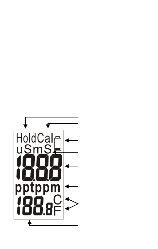
LCD DISPLAY
Hold data on the LCD
Calibration Mode
Low battery indicator
Unit of conductivity
Measured value
Unit of TDS and
Salinity
Unit of liquid
temperature °C or °F
Temperature reading
6
Page 7

Large Display
Salinity Pen
850036
7
Page 8

SETUP MODE
The advanced Setup Mode allows you
to customize the pen’s preferences and
defaults:
1. Press SET to turn the pen on.
2. From Measurement Mode, press SET
for more than 2 seconds to enter Setup
Mode and change parameters.
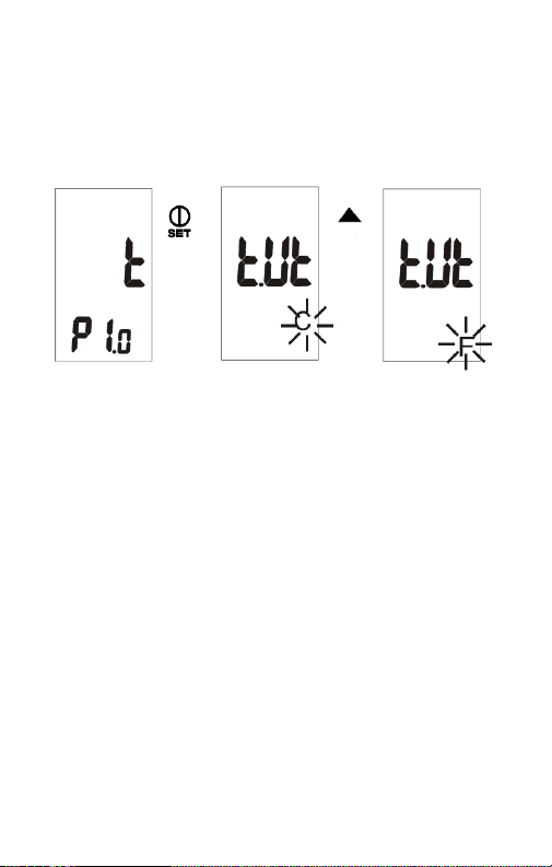
Temperature Units (tUt)
To select the Celsius or Fahrenheit
temperature scale:
1. Press SET for 2 seconds to enter setup.
2. “t” will appear on the primary display of
the LCD and “P1.0” will appear on the
secondary display.
3. Press SET again for less than one
second to enter the unit setting.
4. Press ▲ or ▼ to select C (Celsius) or
F (Fahrenheit). Press SET for less than
one second to conrm the unit selection.
Press SET for more than 2 seconds to
return to P1.0 without saving.
8
Page 9
5. When in P1.0, press ▲ to advance to
SETUP MODE
the next setup function or press SET
for more than 2 seconds to return to
Measurement Mode.
Resetting the Pen (rSt)
When the pen is reset, all parameters
will be reset to factory default values.
1. Press SET for 2 seconds to enter setup.
2. Press ▲ to select the reset pen setting.
“rst” will appear on the main display of
the LCD and “P3.0” will appear on the
secondary display.
3. Press SET again for less than one
second to enter the reset setting.
4. Press ▲ to select Y (yes) or N (no).
9
Page 10

5. Press SET for less than one second to
conrm the selection or press SET for
more than 2 seconds to return to P3.0
without saving.
6. When in P3.0, press ▲ to advance to
the next setup function or press SET
for more than 2 seconds to return to
Measurement Mode.
Calibration Review (CAL)
1. Press SET for 2 seconds to enter setup.
2. Press ▲ to select the calibration review
setting. “CAL” will appear on the primary
display of the LCD and “P4.0” will
appear on the secondary display.
Range 1 Calibration Information:
3. When in P4.0, press SET for less than
one second to enter P4.1 to review the
last calibration concentration. If the pen
is not yet calibrated, “---” will appear on
the LCD.
10
Page 11

Range 2 Calibration Information:
4. When in P4.1, press ▲ to enter P4.2 to
review the last calibration concentration.
If range 2 is not yet calibrated, “---” will
appear on the LCD.
5. When in P4.1 or P4.2, press SET for
less than one second to conrm and
return to P4.0.
6. When in P4.0, press ▲ to advance to
the next setup function or press SET
for more than 2 seconds to return to
Measurement Mode.
Note…
P4.1 and P4.2 Modes allow review of the
calibration information but are not used
during the calibration procedure.
Selecting the Measurement Range (rAn)
There are two measurement ranges.
The pen defaults to auto-ranging:
Salinity
Range 1 0 ~ 10.00 ppt
Range 2 10.1 ~ 70.0 ppt
11
Page 12

To manually select the measurement range:
1. Press SET to turn the pen on.
2. Press ▲ for more than 2 seconds to
select range 1. Press ▲ for more than
2 seconds to select range 2.
CALIBRATION
Selecting the Calibration
Standard Solution
For best results, select a NaCl standard
near the sample value that you are
measuring. Alternatively, use a calibration
solution value that is approximately ⅔ of
the full scale of the measurement range
that you plan to utilize.
Do NOT reuse the calibration solution.
Contaminants in the solution will affect the
calibration and the accuracy. Use fresh
solution each time.
The previous calibration data will be
replaced after re-calibrating. However,
12
Page 13
the pen will retain the calibration data for
other ranges that have not yet been re-
calibrated.
Selecting the Calibration Schedule
Calibration is necessary and should be
performed regularly. Soak the probe for 15
minutes before calibration or measurement
to minimize drift. If the pen is used in the
mid ranges, calibrate the unit monthly.
If the measurement is performed at
extreme temperatures or within the
concentration listed below, calibrate
the unit weekly.
Model Concentration
Salinity Pen < 0.10 ppt > 5.0 ppt
13
Page 14

Salinity Calibration
1. Place the probe into deionized or
distilled water for about 30 minutes to
rinse the probe.
2. Select the NaCl standard for calibration.
3. Pour 3 cm (deep) of solution into two
separate containers (A & B).
4. Press SET to turn the pen on.
5. Rinse the probe in one of the
containers. Gently stir the probe.
6. Dip the rinsed probe into the other
container. Tap the probe on the bottom
of the container to remove air bubbles.
Let the probe stabilize to the solution
temperature (allow 15 minutes).
7. Press CAL for more than 2 seconds to
begin calibration. “CAL” and the salinity
value of the solution will ash on the LCD.
8. Press ▲ or ▼ to adjust the value on the
primary display to match the value of
the standard buffer. You can adjust the
salinity reading ± 30% from the detected
value. If the detected value and the
standard value differ by more than ±
30%, clean or replace the pen.
14
Page 15

9. When “CAL” stops ashing on the
LCD, press SET for less than 1 second
to conrm the value. The pen will
return to Measurement Mode for salt
measurement. To exit Calibration Mode
without saving, press SET for more than
2 seconds. This allows you to retain the
pen’s previous calibration data for the
current range as you proceed. If “CAL”
ashes on the LCD continually, check
that the calibration solution is stable and
that the input value (Step 8) is correct.
10. Repeat Steps 1-9 for other ranges as
needed.
Note…
If the standard value is over the measuring
range or 10% less, the displayed value will
be equal to the range limit or 10% of the
range limit.
15
Page 16

MEASUREMENT PROCEDURES
1. Remove the probe cover from the pen.
2.
Press SET to turn the pen on.
3. The pen defaults to auto-ranging mode.
The auto-ranging function determines
and selects a range that will provide the
greatest resolution and accuracy.
4. To manually select the measurement
range: Press SET to turn the pen on.
Press ▲ for more than 2 seconds to
select range 1. Press ▲ for more than
2 seconds to select range 2.
Note...
Accuracy is a percent of full-scale; use
your pen in the lowest range to achieve
the greatest accuracy. Error codes
E02/E03 will appear on the LCD if the
measured value is below or above the
limit value. Please re-select the range.
16
Page 17

5. Rinse the probe tip with de-ionized or
distilled water before use to remove
any impurities adhering to the probe. If
the probe tip is dehydrated, soak it for
30 minutes to prevent contaminants
from slowing down the measurement
and accuracy.
6. Immerse the probe tip completely into
the sample. Ensure that there are no
air bubbles trapped in the probe slot.
Gently stir the probe to remove air
bubbles, ensuring that the probe tip
is submerged while stirring.
7. Stir the probe gently to create a uniform
sample. Wait about 15 minutes for the
reading to stabilize.
8. The unit of measure will ash on the
LCD to indicate that the pen is in
Measurement Mode. When the
reading is stable, the unit of measure
will stop ashing.
Hold Function
1. Press HLD to freeze the current
readings on the display. “Hold” will
appear on the LCD.
17
Page 18

2. Press HLD again to release the
hold function.
Turning the Pen Off
1. Press SET to turn the pen off from
Measurement Mode.
2. To turn the pen off from Setup Mode,
press SET for more than 2 seconds
to return to Measurement Mode, then
press SET again.
Auto Power Off
1. To save battery life, the pen will
automatically turn off after 20 minutes
of inactivity. To disable this function:
2. Press SET to turn the pen off.
3. Press SET and ▼ simultaneously until
“n” appears on the LCD. Release the
keys to return to Measurement Mode.
Auto-power-off is now disabled.
Note…
The auto-power-off function will be
enabled each time the pen is turned off.
18
Page 19

SPECIFICATIONS
±1% Full Scale
Accuracy
Range
Resolution 0.01 ppt or 0.1 ppt
Calibration One point per range
TDS Factor
Temperature
Coefcient
Reference
Temperature
Operating
Temperature
Battery Life >80 hours continuous use
Weight 2.5 oz (68 g)
Dimensions
± 1 digit (0.0~10.0 ppt)
or ±2% Full Scale
±1 digit (10.1~70.0 ppt)
0.00~10.00 ppt (NaCl)
or 10.1~70.0 ppt (NaCl)
Built-in NaCl conductivity
to TDS factor
Built-in NaCl temperature
coefcient
Fixed at 25°C
0~50°C (32~122°F)
6½" x 1½" x 1½"
(165 x 38 x 38 mm)
19
Page 20

ERROR CODES
Salinity
- - - The pen is in manual ranging 1 but
the salinity measurement is higher
than 10.0 ppt; Press ▲ for more
than 2 seconds to change to manual
ranging 2 or auto-ranging mode.
E03 The salt value is over the range limit
(70.0 ppt) or the pen is damaged;
Put the pen in standard buffer
solution (the buffer concentration
must be lower than the range limit).
If E03 still appears, send the pen to
Sper Scientic for repair.
E04 Error in measuring original data
(damaged temperature sensor,
temperature out of specications
or salinity error). E04 will disappear
when the original error is resolved.
20
Page 21

Temperature
E01 The temperature circuit is
damaged; Send the pen to
Sper Scientic for repair.
E02 The temperature value is below the
range limit (0°C) or the temperature
circuit is damaged; Place the pen
in room temperature for 5 minutes,
if E02 still appears, send the pen
to Sper Scientic for repair.
E03 The temperature value is above
the range limit (50°C) or the
temperature circuit is damaged;
Place the pen in room temperature
for 5 minutes, if E03 still appears,
send the pen to Sper Scientic
for repair.
21
Page 22

22
Page 23

Large Display
Conductivity Pen
850037
23
Page 24

SETUP MODE
The advanced Setup Mode allows you
to customize the pen’s preferences
and defaults:
1. Press SET to turn the pen on.
2. From Measurement Mode, press SET
for more than 2 seconds to enter Setup
Mode and change parameters.
24
Page 25

Temperature Units (tUt)
To select the Celsius or Fahrenheit
temperature scale:
1. Press SET for 2 seconds to enter setup.
2. “t” will appear on the primary display of
the LCD and “P1.0” will appear on the
secondary display.
3. Press SET again for less than one
second to enter the unit setting.
4. Press ▲ or ▼ to select C (Celsius) or
F (Fahrenheit). Press SET for less than
one second to conrm the unit selection.
Press SET for more than 2 seconds to
return to P1.0 without saving.
5. After conrming the temperature unit
selection, you may continue to set other
temperature related parameters by
pressing SET for more than 2 seconds
to return to P1.0.
6. When in P1.0, press SET for more
than 2 seconds to return to
Measurement Mode.
25
Page 26

press " " more than 2 sec to enter
setup mode. Press " "or " " or
" " to select
momentarily again to enter unit setting.
Press " " or " " to select C /F.
Press " " momentarily to confirm the
unit or press " " more than 2 sec to
return to P1.0 without saving.
After confirming the unit, you can
continuously set another temp. related
parameters (except 8371) or press
" " more than 2 seconds to return
to P1.0.
While in P1.0, press " " for more
than 2 seconds to return to measure-
ment mode.
P1.0, then press " "
Reference (Normalization)
Temperature (tnr)
After saving the temperature unit setting,
the pen will automatically enter the
reference temperature setup.
1. Press ▲ to select 20°C or 25°C.
2. Press SET for less than one second
to conrm the value or press SET for
more than 2 seconds to return to P1.0
without saving.
or
Long
pres s
Long
pres s
26
Shor t
pres s
or
Page 27

Temperature Coefcient (tCo)
Press " "or " "
o
o
lue.
P1.1 P 1. 2 P1 .3
1. Press ▲ or ▼ to change the
temperature coefcient from 0.0 to 4.0.
2. Press SET for less than one second
to conrm the value or press SET for
more than 2 seconds to return to P1.0
without conrming the temperature
coefcient value.
27
Page 28

Resetting the Pen (rSt)
NOTE:
Pay attentio n
to the dif
fe-
rence betwee n
short or long
press " "
after setting
the tds value.
When the pen is reset, all parameters
(including calibration information) will be
reset to factory default values.
1. Press SET for 2 seconds to enter setup.
2. Press ▲ to select the reset pen setting.
“rst” will appear on the main display of
the LCD and “P3.0” will appear on the
secondary display.
3. Press SET again for less than one
second to enter the reset setting.
4. Press ▲ to select Y (yes) or N (no).
5. Press SET for less than one second to
conrm the selection or press SET for
more than 2 seconds to return to P3.0
without saving.
28
Page 29

Calibration Review (CAL)
1. Press SET for 2 seconds to enter setup.
2. Press ▲ to select the calibration review
setting. “CAL” will appear on the primary
display of the LCD and “P4.0” will
appear on the secondary display.
Range 1 Calibration Information:
3. When in P4.0, press SET for less than
one second to enter P4.1 to review
the last calibration concentration. If
the pen is not yet calibrated, “---”
will appear on the LCD.
Range 2 Calibration Information:
4. When in P4.1, press ▲ to enter P4.2
to review the last calibration concentration.
If range 2 is not yet calibrated, “---” will
appear on the LCD.
Note…
When in P4.1 or P4.2, press SET for
less than one second to conrm and
return to P4.0.
29
Page 30

P4.1 and P4.2 Modes allow review of the
calibration information but are not used
during the calibration procedure.
When in Temperature Parameter (P1.0),
Resetting the Pen (P3.0) or Calibration
Review (P4.0) Setup Modes, press SET
for more than 2 seconds to return to
Measurement Mode.
30
Page 31

Selecting the Measurement Range (rAn)
2.Pr ess " " or " " mo re than 2
seco nds to se lect th e ran ge .
To manua l selec t the m ea sur ement
rang e:
1. Turn o n the met er and st ay at nor mal
meas ureme nt mode .
Pres s" "
> 2 seco nd
Pres s" "
> 2 seco nd
There are two measurement ranges.
The pen defaults to auto-ranging
Conductivity
Range 1
Range 2
0 ~ 1999 uS
0 ~ 19.99 mS
To manually select the measurement range:
1. Press SET to turn the pen on.
2. Press ▲ for more than 2 seconds to
select range 1. Press ▲for more than
2 seconds to select range 2.
(Def ault)
31
Page 32

CALIBRATION
Selecting the Calibration
Standard Solution
For best results, select a conductivity
standard near the sample value that
you are measuring. Alternatively, use
a calibration solution value that is
approximately 2/3 of the full scale of
the measurement range that you plan
to utilize.
For example, in the 0 to 1999 uS range,
use 1413 uS solution for calibration.
Do NOT reuse the calibration solution.
Contaminants in the solution will affect the
calibration and the accuracy. Use fresh
solution each time.
Refer to the following table. For best
results, use the recommended solution
for various conductivity ranges
32
Page 33

Conductivity
Measuring Range
1 0 ~ 1999 uS 600 ~ 1700 uS
2 0 ~ 19.99 mS 6.0 ~ 17.00 ms
Recommended Cal.
Solution Range
The previous calibration data will be
replaced after re-calibrating. For example,
if you previously calibrated the conductivity
pen at 1413 uS in the 0 ~ 1999 uS range,
when you re-calibrate at 1500 uS again
(also in the 0 ~ 1999 range), the previous
1413 uS calibration point will be replaced
in this range (0 ~ 1999 uS). However,
the pen will retain the calibration data for
other ranges that have not yet been re-
calibrated.
Note…
The temperature coefcient of the pen
defaults to 2.1% per °C and provides good
results for most applications. To reset
the coefcient, see page 27. You may
also refer to Appendix B on page 47 to
calculate the temperature coefcient.
33
Page 34

The default value of the reference
temperature is set at 25°C. To normalize to
a different value, see page 33. Determine
the calibration standard value for your
reference temperature before resetting
the reference temperature. Contact the
solution distributor for the calibration
standard value of the solution.
Selecting the Calibration Schedule
Calibration is necessary and should be
performed regularly. Soak the probe
for 15 minutes before calibration or
measurement to minimize drift. If the pen
is used in the mid ranges, calibrate the
unit monthly.
If the measurement is performed at
extreme temperatures or within the
concentration listed below, calibrate
the unit weekly.
Model Concentration
Conductivity Pen < 100 uS > 2 mS
34
Page 35

Conductivity Calibration
CALIBRATION
3. Pour 3 cm (deep) of buffer solution
into two separate containers (A & B).
4. Press SET to turn the meter on.
Press CAL for more than 2 seconds
to enter Calibration Mode.
5. Rinse the probe in one of the
containers. Gently stir the probe.
6. Dip the rinsed probe into the other
container. Tap the probe on the
bottom of the container to remove air
bubbles. Let the probe stabilize to
the solution temperature (allow 15
minutes).
1. Place the probe into deionized or
2. Select the conductivity standard for
3. Pour 3 cm (deep) of calibration solution
4. Press SET to turn the pen on. Press
5. Rinse the probe in one of the
6. Dip the rinsed probe into the other
distilled water for about 30 minutes to
rinse the probe.
calibration. (Refer to page 26)
into two separate containers (A & B).
CAL for more than 2 seconds to enter
Calibration Mode.
containers. Gently stir the probe.
container. Tap the probe on the bottom
of the container to remove air bubbles.
Let the probe stabilize to the solution
temperature (allow 15 minutes).
A (Step 5) B (Step 6)
35
Page 36

7. Press CAL for more than 2 seconds to
begin calibration. The conductivity value
of the solution will ash on the LCD.
8. Press ▲ or ▼ to adjust the value on
the primary display to match the value
of the standard buffer. You can adjust
the conductivity reading ± 30% from the
detected value. If the detected value
and the standard value differ by more
than ± 30%, clean or replace the pen.
Example:
Standard: 10 uS; Detected value: 19 uS
Adjustable range: ± 5.7 uS (19*30%)
Under the above situation, the values
differ by over 30%.
Note…
If the standard value is over the measuring
range or 10% less, the displayed value will
be equal to the range limit or 10% of the
range limit.
Example 1:
Standard: 22 uS; Detected value: 19 uS
Adjustable range: ± 5.7 uS (19*30%)
36
Page 37

Although the values differ less than 30%,
the 22 uS is still over the range limit. The
maximum input value is 19.99 uS.
Example 2:
Standard: 1.6 mS; Detected value: 2.1 mS
Adjustable range: ± 0.63 mS (2.1*30%)
Although the measured value differs less
than 30%, the 1.6 mS is still less than the
10% range limit (1.99). The maximum
input value is 1.99 mS.
9. When “CAL” stops ashing on the LCD,
press SET for less than 1 second to
conrm the value. The pen will return to
Measurement Mode. To exit Calibration
Mode without saving, press SET for
more than 2 seconds. This allows you
to retain the pen’s previous calibration
data for the current range as you
proceed. If “CAL” ashes on the LCD
continually, check that the calibration
solution is stable and that the input
value (Step 8) is correct.
10. Repeat Steps 1-9 for other ranges
as needed.
37
Page 38

Note…
Remove the cover
from the bottom
of meter to expose
the electrode.
Elect rode
Remove the cover
from the bottom
of meter to expose
the electrode.
Electrode
3.
The meter is default in aut o-ranging
status once powered on.
Auto-ranging determi nes and selects
a range which gives you the gr eatest
resolution and accuracy. Altern atively,
you can manually select th e ranges.
For example, if you prefer the meter
to display a reading as 0.50 mS
instead of 500 µS, you just need to
press “ “ m
select 19.99 mS range when you
are in normal measurement mode.
ore than 2 seconds
to
See page 12
for the detail
When the pen is switched from
Measurement Mode to Calibration Mode,
it will display the factory default value.
Therefore, if the pen was previously
calibrated, the display may appear to jump
to the factory default value when entering
Calibration Mode
MEASUREMENT PROCEDURES
1. Remove the probe cover from the pen.
Remove the cover from
the bottom of pen to
expose the electrode.
38
Page 39

Remove the cover
from the bottom
of meter to expose
the electrode.
Electrode
3.
The meter is default in aut o-ranging
status once powered on.
Auto-ranging determi nes and selects
a range which gives you the gr eatest
resolution and accuracy. Altern atively,
you can manually select th e ranges.
For example, if you prefer the meter
to display a reading as 0.50 mS
instead of 500 µS, you just need to
press “ “ m
select 19.99 mS range when you
are in normal measurement mode.
ore than 2 seconds
to
2. Press SET to turn the pen on.
3. The pen defaults to auto-ranging mode.
The auto-ranging function determines
and selects a range that
will provide the greatest resolution
and accuracy.
4. The pen also provides a manual range
option. For example, to view a reading
of 0.50 mS rather than 500 uS: From
Measurement Mode, press ▲ for more
than 2 seconds to select the 19.99 mS
range. See page 31 for instructions on
manually selecting the range.
See page 12
for the detail
Note...
Accuracy is a percent of full-scale; use
your pen in the lowest range to achieve
the greatest accuracy. Error codes
E02/E03 will appear on the LCD if the
measured value is below or above the
limit value. Please re-select the range.
39
Page 40

5. Set the temperature coefcient to the
correct value. The pen defaults to 2.1%
per °C, which will typically provide
good results. See page 27 to reset the
temperature coefcient.
6. Select the reference temperature. The
pen defaults to 25°C. To more than
2 seconds to select the 19.99 mS
range. See page 26 for instructions on
manually selecting the range. normalize
to 20°C instead, see page 26.
7. Rinse the probe tip with de-ionized or
distilled water before use to remove
any impurities adhering to the probe.
If the probe tip is dehydrated, soak it
for 30 minutes to prevent contaminants
from slowing down the measurement
and accuracy.
8. Immerse the probe tip completely into
the sample. Ensure that there are no
air bubbles trapped in the probe slot.
Gently stir the probe to remove air
bubbles, ensuring that the probe tip is
submerged while stirring.
40
Page 41

9. Stir the probe gently to create a uniform
8351
8351
sample. Wait about 15 minutes for the
reading to stabilize.
10. The unit of measure
will ash on the LCD to
indicate that the pen is in
Measurement Mode. When
the reading is stable, the
unit of measure will stop
ashing.
Hold Function
1. Press HLD to freeze the
current readings on the
display. “Hold” will appear
on the LCD.
2. Press HLD again to release
the hold function.
41
Page 42

SPECIFICATIONS
Accuracy
Range
Resolution 1 uS or 0.01 mS
Temperature
Accuracy
Temperature
Resolution
Calibration One point per range
Temperature
Coefcient
Reference
Temperature
Operating
Temperature
Battery Life >80 hours continuous use
Weight 2.5 oz (68 g)
Dimensions
± 1% Full Scale
± 1 digit
0 ~ 1999 uS or
0 ~ 19.99 mS
± 2°F
± 1°C
0.1°C/°F
0 ~ 4.0%/°C
20°C or 25°C
0~50°C (32~122°F)
6½" x 1½" x 1½"
(165 x 38 x 38 mm)
42
Page 43

ERROR CODES
Conductivity
- - - The pen is in manual ranging 1 but
the conductivity measurement is
higher than 1999 uS; Press ▲ for
more than 2 seconds to change to
manual ranging 2 or auto-ranging
mode.
E03 The conductivity value is over
the range limit (19.99 mS) or the
pen is damaged; Put the pen in
standard buffer solution (the buffer
concentration must be lower than
the range limit). If E03 still appears,
send the pen to Sper Scientic for
repair.
E04 Error in measuring original data
(damaged temperature sensor or
temperature out of specications)
results in this conductivity value
error; Refer to the temperature
error codes (page 44). E04 will
disappear when the temperature
error is resolved.
43
Page 44

Temperature
E01 The temperature circuit is
damaged; Send the pen to Sper
Scientic for repair.
E02 The temperature value is below the
range limit (0°C) or the temperature
circuit is damaged; Place the pen
in room temperature for 5 minutes,
if E02 still appears, send the pen to
Sper Scientic for repair.
E03 The temperature value is above
the range limit (50°C) or the
temperature circuit is damaged;
Place the pen in room temperature
for 5 minutes, if E03 still appears,
send the pen to Sper Scientic
for repair.
44
Page 45

Appendices
45
Page 46

APPENDIX A:
Program Function Default Note
P1.1 Select °C/°F °C Temp unit
P1.2 Reference
Temperature
P1.3 Temperature
Coefcient
P3.1 Factory
Default
P4.1 Viewing
previous
calibration
data
P4.2 Viewing
previous
calibration
data
25°C Selectable
25°C or
20°C
2.1%
/°C
NO Retain
---- No cal
---- No cal
Adjustable
0.4 ~ 10%
your
current
settings
data for
1st range
data for
2nd range
46
Page 47

APPENDIX B:
Temperature Effect
Conductivity measurements are
temperature dependent; if the temperature
increases, conductivity increases. For
example, the conductivity measured in a
0.01 M KCl solution at 20°C is 1.273 mS/
cm, whereas at 25°C, it is 1.409 mS/cm.
The concept of reference temperature
(normalization temperature) was
introduced to allow the comparison
of conductivity results obtained at
different temperatures. The reference
temperature is usually 20°C or 25°C. The
pen measures the actual conductivity
and temperature, then converts it
to the reference temperature using
a temperature correction function
and displays the conductivity at the
reference temperature. It is mandatory to
associate the temperature together with
a conductivity result. If no temperature
correction is applied, the conductivity
47
Page 48

exam ple, if t he T DS valu e is ppm, t he cond uctiv ity
valu e must be i n uS; if th e TD S value i s in ppt, t he
cond uctiv ity val ue must b e in mS.
Chec k this nu mber by m ultip lying t he cond uctiv ity
read ing by th e facto r in the ab
ove fo rmula a nd the
resu lt is the TDS i n ppm.
Appendix D: Temperature Effect
Cond uctiv ity mea surem ents ar e tempe ratur e
depe ndent , if the te mpera ture in creas es, con ducti vity
incr eases . eg: the c onduc tivit y measu red in a 0. 01
0
M KCl so lutio n at 20 C is 1 .273 mS /cm, wh ereas , at
0
25 C, it is 1 .409 mS /cm.
The co ncept o f refer ence te mpera ture (N ormal izati on
temp eratu re) was i ntrod uced to a llow th e compa rison
of con ducti vity re sults o btain ed at diffe rent te mpera ture.
0 0
The re feren ce temp eratu re is usu ally 20 C or 25 C.
The co nduct ivity m eter me asure s the act ual CON D.
and te mpera ture an
d then c onver ts it to th e refer ence
temp eratu re usin g a tempe ratur e corre ction f uncti on
and di splay s the con ducti vity at t he refe rence t emp..
It is ma ndato ry to alw ays ass ociat e the tem perat ure
toge ther wi th a cond uctiv ity res ult. If n o tempe ratur e
corr ectio n is appl ied, th e condu ctivi ty is the v alue
take n at meas ureme nt temp eratu re. The 8 30x met er
used l inear t emper ature c orrec tion.
Line ar temp eratu re corr ectio n:
In mod erate ly and hi ghly co nduct ive sol ution s,
temp eratu re corr ectio n can be ba sed on a li near
equa tion in volvi ng a temp era
ture c oeffici ent ( ). The
coeffi cient i s usual ly expr essed a s a condu ctivi ty
0
vari ation i n %/ C.
Line ar temp eratu re corr ectio n is used , e.g. fo r salin e
, acid s and lea ching s oluti ons.
is the value taken at the measurement
temperature. The Large Display Salinity
(Model 850036) and Conductivity (Model
850037) Pens automatically use linear
temperature correction.
Linear Temperature Correction
In moderately and highly conductive
solutions, temperature correction can be
based on a linear equation involving a
temperature coefcient (θ). The coefcient
is usually expressed as a conductivity
variation in %/°C. Linear temperature
correction is used for saline, acids, and
leaching solutions.
Where:
K
= Conductivity at Tref
Tref
KT = Conductivity at T
T
= Reference temperature
ref
T = Sample temperature
100
KTr ef=
100+
( )
T
ref
T-
KT
θ = Temperature coefcient
48
Page 49

Note…
APPENDICES
The correction is accurate only within a
limited temperature range around T1 and
T2. The greater the difference between T
and Tref, the higher the risk of error.
Calculating Temperature Coefcients (θ)
By measuring the conductivity of a
sample at temperature T1 close to Tref
and another temperature T2, you can
calculate the temperature coefcient by
using the following equation:
T2 should be selected as a typical sample
temperature and should be approximately
10°C different from T1. The temperature
coefcients of the following electrolytes
generally fall into the following ranges:
49
Page 50

Acids: 1.0 - 1.6%/°C
Bases: 1.8 - 2.2%/°C
Salts: 2.2 - 3.0%/°C
Drinking water: 2.0%/°C
Ultra-pure water: 5.2%/°C
Average temperature coefcients of
standard electrolyte solutions are
expressed as %/°C of the conductivity
value at 25°C.
Temp
Range
°C
15 ~25 1.725 1.863 1.882 1.981
15 ~ 25
~35
25 ~ 35
KCl
1M
1.730
(15 ~ 27°C)
1.762
(25 ~ 27°C)
KCl
0.1 M
1.906
1.978
50
KCl
0.01 M
1.937
(15 ~ 34°C)
1.997
(25 ~ 34°C)
Saturated
NaCl
2.041
2.101
Page 51

Battery Replacement,
Maintenance,
& Troubleshooting
51
Page 52

BATTERY REPLACEMENT
BATTERY REPLACEMENT
1. Press SET to turn the pen off.
2. Remove the battery cover located
on the top of the unit by rotating
counterclockwise. Do NOT discard the
black washer.
3. Remove the old batteries and replace
with 4 new LR44 batteries, ensuring
correct polarity.
4. Replace the battery cover by rotating in
the clockwise direction.
If the pen will not be in
use for a month or longer,
remove the batteries and
replace when ready to
use the pen.
52
Note…
Page 53

MAINTENANCE
Ensure that the probe is clean before use
and storage. To clean:
1. Remove the probe cap.
2. Rinse the probe carefully in deionized
water, replace the cap, and store dry in
an environment of 0 ~ 50°C.
Note…
If the probe has been exposed to a solvent
that is immiscible with water, clean the
probe with a solvent that is miscible with
water (i.e., ethanol or acetone), then
carefully rinse with water.
53
Page 54

TROUBLESHOOTING
Pen does not turn on:
1. Press SET for more than 1 second.
2. Check that the batteries are in place,
making good contact, and placed with
correct polarity.
3. Replace with new batteries and
try again.
4. Remove the batteries for one minute
and then replace the batteries.
Display disappears:
If the low battery icon appears on the LCD
before the display disappears, replace with
new batteries.
Air bubbles adhering to the probe:
It is typical for air bubbles to adhere to the
large slot in the probe. These air bubbles
will greatly affect the accuracy and should
be removed.
54
Page 55

Many a ir bu bbles adhe red !
To remove the air bubbles:
1. Stir the probe.
2. Dip the probe into the solution at
an oblique angle (at a slant, not
perpendicular to solution). Dipping
the probe perpendicularly will cause
air bubbles to form.
3. Soak the probe in solution for 15-30
minutes. Inspect the probe carefully for
air bubbles.
4. If air bubbles remain on the probe, tap
the bottom of the container gently and
stir the probe.
5. If the preceding methods fail, remove
the probe from the solution and blow on
the probe to remove the air bubbles.
55
Page 56

WARRANTY
Sper Scientic warrants this product against
defects in materials and workmanship for
a period of one (1) year from the date of
purchase, and agrees to repair or replace
any defective unit without charge. If your
model has since been discontinued, an
equivalent Sper Scientic product will
be substituted if available. This warranty
does not cover probes, batteries, battery
leakage, or damage resulting from accident,
tampering, misuse, or abuse of the product.
Opening the pen to expose its electronics
will void the warranty.
To obtain warranty service, ship
the unit postage prepaid to:
SPER SCIENTIFIC, LTD.
8281 E. EVANS RD., SUITE #103
SCOTTSDALE, AZ 85260
Be sure to include your name, address,
phone number, and a detailed explanation
of why you are returning the item. Mail your
warranty card within 10 days or register
online at: www.sperscientic.com.
Revised 03/15/13
56
 Loading...