

Page 1

AquaShock® Water Purity Kit
850034K
Page 2

AquaShock® Water Purity Kit 850034K
Copyright ©2014 by Sper Scientic
ALL RIGHTS RESERVED
Printed in the USA
The contents of this manual may not be reproduced or transmitted
in any form or by any means electronic, mechanical, or other
means that do not yet exist or may be developed, including
photocopying, recording, or any information storage and retrieval
system without the express permission from Sper Scientic.
Sper Scientic
8281 E. Evans Rd., Suite #103, Scottsdale, AZ 85260
Tel: (480) 948-4448 Fax: (480) 967-8736
Web: www.sperscientic.com
2 3
Page 3

TABLE OF CONTENTS
INTRODUCTION .....................................4
FEATU RES..........................................5
MATERIALS SUPPLIED................................5
OPTIONAL ACCESSORIES ............................5
LCD DISPLAY .......................................6
POWER SUPPLY .....................................7
KEYPAD ............................................8
SETUP MODE .......................................9
CALIBRATION ......................................14
MEASUREMENT PROCEDURES .......................17
SPECIFICATIONS ...................................23
WARRANTY .......................................24
3
Page 4

INTRODUCTION
The Sper Scientic AquaShock® Water Purity Meter is the most
waterproof, rugged and reliable Conductivity/TDS meter on the
market. It is fully waterproof, including probe connections, when
used with the AquaShock® probe. As with all AquaShock®
meters, the Water Purity Meter is fully shockproof, oats, and
features a double injection molded case with an integral protective
soft grip outer layer, high end antishock, LED backlight display,
and is powered by the latest environmentally friendly, long lasting,
rechargeable Lithium Ion battery. The meter is highly accurate and
stable, very intuitive and includes all of the functions required by
most users. Sper Scientic guarantees you will not nd any meters
more rugged and reliable than AquaShock®.
4 5
Page 5

FEATURES
• Floats
• Shockproof
• IP67 Waterproof
• Protective soft grip outer layer
• Rechargeable Lithium Ion battery
• Also accepts standard BNC probes
• Multi-line display LCD screen
• Reads Conductivity and TDS
• Auto Ranging
• Automatic Temperature Compensation
• Celsius or Fahrenheit selectable
• 99 data points memory for each measurement type
• Calibration point review
• Internal clock and calendar
• Maximum, minimum and average
• Hold function
• Low battery indicator
• Backlight
MATERIALS SUPPLIED
• Meter
• Conductivity/TDS/ATC Probe
• Waterproof Probe Input Covers
• 1 Lithium 1450mAh 7.4 V Battery
• DC Power Adapter
• Instrution Manual
• Hard Carrying Case
OPTIONAL ACCESSORIES
• 840092 Bench-Top Tripod
• 840093 Field Tripod
• 850034P Replacement AquaShock® Conductivity/TDS Probe
5
Page 6
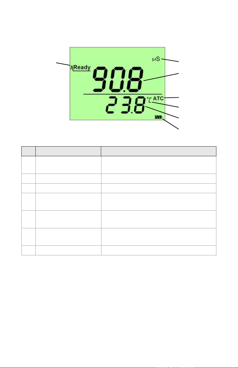
LCD DISPLAY
1 2
3
4
5
6
7
Name Description
1 Ready Displayed when measuring
results are stable
2 Scale Unit Current measurement scale unit
3 Measuring Results Current measurement value
4 ATC Automatic Temperature
Compensation indicator
5 Temperature Scale Current temperature
measurement unit
6 Temperature Value Current temperature
measurement value
7 Battery Icon Current battery power level
6 7
Page 7
LCD DISPLAY
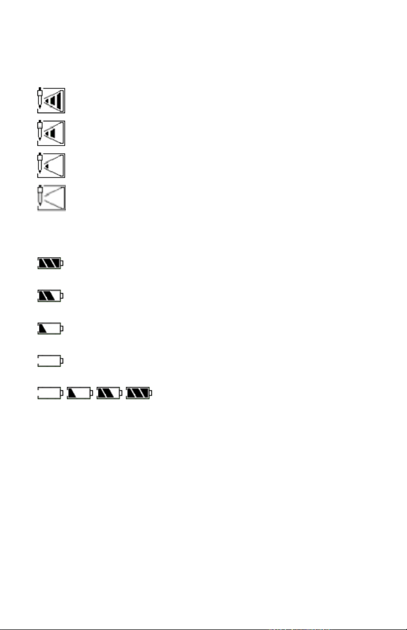
Probe Life Icon:
More than 90% life remaining
More than 85– 90% life remaining
More than 80- 85% life remaining
Less than 80% life remaining
Battery Power Icon:
Battery voltage is more than 7.7V shows full.
Battery voltage between 7.2V and 7.7V shows 2 cells.
Battery voltage between 6.6V and 7.2V shows 1 cell.
Battery voltage less than 6.6V shows 0 cells and ashes.
Display showing battery charging from
less than 6.6V to fully charged.
POWER SUPPLY
This meter is powered by one rechargeable Lithium 7.4V (1450
mAh) battery. The DC power adapter can be used to charge the
battery even when the meter is turned off. This meter includes a
charge protection function and will automatically stop charging
when the battery is full. A complete re-charge takes approximately
8 hours.
7
Page 8
Water Purity Meter
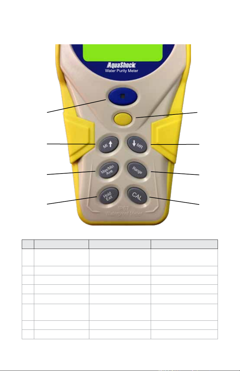
KEYPAD
1
3
5
7
Name 1st Function 2nd Function
1 Power/Backlight/
Low Battery
2 Setup Setting parameters Conrm setting
3 MI↑ Store data ↑
4 MR↓ Recall data ↓
5 Max/Min/Ave Max/Min/Ave
6 Range Switch measuring
7 Hold/Exit Hold Exit
8 CAL Calibration
Power on/off Backlight on/off
scale
2
4
6
8
8 9
Page 9

SETUP MODE
The Setup Mode allows you to customize the following meter
preferences and defaults:
• Temperature Scale
• Clock Setting
• Restore Factory Defaults
• Set ATC Temperature Coefcient
• Set TDS Factor
1. Press POWER to turn the meter on before performing any
setup function.
Temperature Units
1. Press SETUP to enter the Setup Mode.
2. Press SETUP to enter the Set Temperature screen.
3. The unit °C or °F will ash on the LCD.
4. Press ↑ or ↓ to select the °C or °F temperature unit.
5. Press SETUP to save and return to Normal Mode.
6. Press EXIT to return to Normal Mode without saving the selection.
Note…
When the temperature reading is outside the range, the display will
show “HHH” (high) or “LLL” (low).
Real Time Clock
1. Press SETUP to enter the Setup Mode.
2. Press ↑ or ↓ to select the Set Clock screen (see Fig. A).
3. Press SETUP to set the year (see Fig. B). The value will ash
on the LCD.
4. Press ↑ to increase the value by 1. Hold down ↑
to continually increase the value.
Press ↓ to decrease the value by 1. Hold down ↓
to continually decrease the value.
9
Page 10

Press SETUP to save and the meter automatically
moves to the month setting (see Fig. C.).
5. Repeat step 4 to adjust the month, day, hour, and minute (see
Fig. D, E & F).
6. Press EXIT to return to Normal Mode without saving.
Note...
This procedure adjusts the meter’s internal clock which is a 24
hour format only. The internal clock will function when the meter is
turned off if the battery is installed.
Fig. A
Fig. C
Fig. E
Fig. B
Fig. D
Fig. F
10 11
Page 11

Restore Factory Settings
1. Press SETUP to enter the Setup Mode.
2. Press ↑ or ↓ to select the Restore Factory Settings screen
(see Fig. A).
3. Press SETUP to conrm selection. “NO” will ash on the LCD.
(see Fig. B).
4. Press ↑ or ↓ to select “YES” or “NO”. (see Fig. C).
5. When “YES” is displayed, press SETUP to conrm and all
parameters will restore to factory settings (except the clock)
and the meter returns to Normal Mode.
6. Press EXIT to return to Normal Mode without saving.
Fig. A Fig. B
Fig. C
Factory Defaults
Parameter Name Parameter
Value
Date 2011-1-1 0:0
CAL Standard
TDS Factor 0.50
Offset
Temperature 77.0°F
(25.0°C)
Temperature Unit °F
Temperature Coefcient 2.1%
Saved Point
11
Page 12

Set ATC Temperature Coefcient
1. Press SETUP to enter the Setup Mode.
2. Press ↑ or ↓ to select the Set Temperature Coefcient screen
(See Fig. A.).
3. Press SETUP to enter the Set Temperature Coefcient
screen. The current value setting will ash (see Fig. B).
4. Press ↑ once to increase the value. Hold down ↑ to
continually increase the value.
Press ↓ once to decrease the value. Hold down ↓ to
continually decrease the value.
The range may be set from 0.0% to 10.0%.
5. Press SETUP to save and return to Normal Mode.
6. Press EXIT to return to Normal Mode without saving change.
Fig. A Fig. B
To calculate the temperature compensation coefcient:
1. Set temperature coefcient to 0%.
2. Put conductivity probe into the standard calibration solution.
3. After 5 minutes record the rst temperature reading and the
corresponding conductivity value.
4. Heat or cool the solution. After a change of 5° to 10°C record
the second temperature reading along with the corresponding
conductivity value.
5. Calculate temperature coefcient by formula below:
TC = temperature coefcient
CT1 = conductivity value when temperature is 1
CT2 = conductivity value when temperature is 2
T1 = temperature value 1
T2 = temperature value 2
25 = 25°C
12 13
Page 13

Set TDS Factor
1. Press SETUP to enter the Set up mode.
2. Press ↑ or ↓ to select the Set TDS Factor screen (see Fig. A).
3. Press SETUP to enter the mode, the current value setting
will ash (see Fig. B).
4. Press ↑ once to increase the value. Hold down ↑
to continually increase the value.
Press ↓ once to decrease the value. Hold down ↓
to continually decrease the value.
The range may be set from 0.40 to 1.00.
5. Press SETUP once to conrm the TDS factor value
and return to Normal Mode.
6. Press EXIT once to return to Normal Mode without
saving changes.
Fig. A Fig. B
Cond.
value at
25°C
84 μS 40.38 0.5048 38.04 0.4755 50.50 0.6563
447 μS 225.6 0.5047 215.5 0.4822 300.0 0.6712
1413 μS 744.7 0.5270 702.1 0.4969 1000 0.7078
1500 μS 757.1 0.5047 737.1 0.4914 1050 0.7000
8974 μS 5101 0.5685 4487 0.5000 7608 0.8478
12880 μS 7447 0.5782 7230 0.5613 11,367 0.8825
15000 μS 8759 0.5839 8532 0.5688 13,455 0.8970
80 mS 52,168 0.6521 48,384 0.6048 79,688 0.9961
TDS KCl TDS NaCl TDS 442 TDS Your
ppm Factor ppm Factor ppm Factor ppm Factor
13
Material
Page 14

CALBRATION
Before calibration, place the probe in the standard calibration
solution. If measured values exceed the standard solution
concentration by ±20%, re-clean your probe or replace it.
Conductivity Calibration
Press RANGE to choose the conductivity scale.
1. Press CAL for 2 seconds to enter the calibration mode.
The meter will automatically select the correct range.
The measured value is displayed above the line, the set
calibration value is shown ashing below the line (see Fig. A).
2. Press ↑ once to increase the Calibration value.
Hold down ↑ to continually increase the value.
Press ↓ once to reduce the Calibration value.
Hold down ↓ to continually reduce the value (see Fig. B).
3. Press SETUP to save the value and exit the calibration
mode (see Fig. C).
4. Repeat steps 1-3 to calibrate at other points.
5. Press EXIT to return to Normal Mode without saving changes.
Fig. A Fig. B
Fig. C
14 15
Page 15

TDS Calibration
Press RANGE to choose the TDS scale.
1. Press CAL for 2 seconds to enter the calibration mode.
The meter will automatically select the correct range.
The measured value is displayed above the line, the set
calibration value is shown ashing below the line (see Fig. A).
2. Press ↑ once to increase the calibration value.
Hold down ↑ to continually increase the value (see Fig. B).
Press ↓ once to reduce the Calibration value.
Hold down ↓ to continually reduce the value.
3. Press SETUP to save the value and exit the calibration mode
(see Fig. C).
4. Repeat steps 1-3 to calibrate at other points.
5. Press EXIT to return to Normal Mode without saving changes.
Fig. A Fig. B
Fig. C
15
Page 16

View Calibration Points
1. Press RANGE to choose the scale you wish to view.
2. Press SETUP to enter the Setup Mode.
3. Press ↑ or ↓ to select the View Cal Data screen (see Fig. A).
4. Press SETUP to enter the View Cal Data Mode. The date
and time is a cyclic display (the Conductivity scale will
display as in Fig. B and Fig. C. The TDS scale will display
as in Fig. D and Fig. E). If there are no calibration points
set the display will show “- - - -” (see Fig. F).
5. Press ↑ to view the previous Cal point. Repeat to
view all previous Cal points.
Press ↓ to view the next Cal point. Repeat to view
additional Cal points.
6. Press SETUP or EXIT to return to Normal Mode.
Fig. A Fig. B
Fig. C
Fig. E Fig. F
Fig. D
Page 17

MEASUREMENT PROCEDURES
Note…
If the ATC Temperature Probe iMEAUs not connected, the display
will read as in Fig. A. No measurement can be performed until the
ATC jack is connected.
Fig. A
Auto Ranging:
The meter will measure conductivity in the μS/cm and mS/cm
scales and will calculate the TDS value in ppm or ppt according to
the TDS conversion coefcient that was entered in the TDS Factor
set up procedure.
During measurement and calibration this meter will automatically
select the correct range. Measurement ranges are as follows:
Conductivity TDS
1 0.00-19.99 μS/cm 0.00-9.99 ppm
2 0.0-199.9 μS/cm 10.0-99.9 ppm
3 0-1999 μS/cm 100-999 ppm
4 0.00-19.99 mS/cm 1.00-9.99 ppt
5 0.0-199.9 mS/cm 10.0-199.9 ppt
17
Page 18

Turning the Meter On/Off
1. Press POWER to turn the meter on. The meter will default
to the last used measurement and temperature scales.
2. Press and hold POWER for 2 seconds to turn the meter off.
Indicator Light Descriptions
Meter Status Indicator Status
Power off Light off
Power on Green light on for 5 seconds, then light off
Low battery Red light ashing every 5 seconds
Charging battery Blue light on
Scale Selection
1. Press RANGE to switch between the Conductivity (µS & mS)
and TDS (ppm & ppt) scales (see Fig. A and Fig. B).
Fig. A Fig. B
18 19
Page 19

Saving to Memory
1. Press MI to save the current measured value and view the
data point number (see Fig. A).
2. Up to 99 Memories can be saved for both Conductivity and
TDS. If the saved memory exceeds 99, the new data will be
written over saved memories beginning with #1.
Fig. A
19
Page 20

Recall Memory
1. Press RANGE to select the scale for recall.
2. Press MR to enter the Recall mode and view the last saved
reading (see Fig. A and Fig. B). The date and time are on
cyclical display. If there is no saved data “- - - -“ is
displayed (see Fig. C).
3. Press ↑ or ↓ to view the saved data points. Press ↑ to view
the data points increasing by 1. Press ↓ to view the data
points decreasing by 1.
4. Press EXIT to exit the Recall Mode and return to Normal Mode.
Fig. A Fig. B
Fig. C
20 21
Page 21

Clear Memory
1. Press MI and MR simultaneously for 2 seconds to clear all
memory (see Fig. A). The meter will return to Normal mode.
Fig. A
Hold
1. Press HOLD to hold the value (see Fig. A).
2. Press HOLD to release the hold value.
Note…
When in Hold Mode, all other functions will be disabled except
turning the meter off, backlight function, saving and exiting
Hold Mode.
Fig. A
21
Page 22

Maximum, Minimum and Average
1. Press RANGE to select the scale.
2. Press MAX/MIN/AVE, the maximum recorded value will
appear on the LCD (see Fig. A and Fig. B. The date and time
are on cyclical display, If no measurements have
been taken, “- - - -” is displayed (see Fig. C).
3. Press MAX/MIN/AVE, the minimum recorded value will
appear on the LCD (see Fig. D and Fig. E). The date and time
are on cyclical display. If no measurements have been taken,
“- - - -” is displayed (see Fig. F).
4. Press MAX/MIN/AVE, the average recorded value will appear
on the LCD. The date and time are on cyclical display. If no
measurements have been taken, “- - - -” is displayed.
5. Press MAX/MIN/AVE to return to the regular mode.
Fig. A Fig. B
Fig. C
Fig. D
22 23
Page 23

Fig. E Fig. F
SPECIFICATIONS
Mode Temperature Conductivity TDS
Range 32 to 212°F
0 to 100°C
Resolution 0.1°C or 0.1°F 0.01 μS,
Accuracy ±1.0°C / ±0.9°F ±1% full scale ±1% full scale
Input Temperature
Probe
Connector
Calibrate
Memory
Temperature
Compensation
Operating
Temperature
Battery
Specications
Battery Life
5 Points (1 point in each of the 5 ranges)
99 points per scale (Conductivity, TDS)
Automatic (ATC) from 32-212ºF (0~100ºC)
32-122ºF (0~50ºC)
Lithium 1450 mAh (DC7.4V) battery
> 80 Hours
0 to 19.99 μS
0 to 199.9 μS
0 to 1999 μS
0 to 19.99 mS
0 to 199.9 mS
0.1 μS,
1 μS,
0.01 mS,
0.1 mS
BNC Connector
0.0 to 9.99 ppm
10.0 to 99.9 ppm
100 to 999 ppm
1.0 to 9.99 ppt
10.0 to 199.9 ppt
0.01 ppm,
0.1 ppm,
1ppm,
0.01 ppt,
0.1 ppt
23
Page 24

WARRANTY
Sper Scientic warrants this product against defects in materials
and workmanship for a period of ve (5) years from the date
of purchase, and agrees to repair or replace any defective unit
without charge. If your model has since been discontinued, an
equivalent Sper Scientic product will be substituted if available.
This warranty does not cover probes, batteries, battery leakage,
or damage resulting from accident, tampering, misuse, or abuse
of the product. Opening the meter to expose its electronics will
break the waterproof seal and void the warranty.
To obtain warranty service, ship the unit postage prepaid to:
SPER SCIENTIFIC LTD.
8281 East Evans Road, Suite #103
Scottsdale, AZ 85260
The defective unit must be accompanied by a description of the
problem and your return address. Register your product online at
www.sperscientic.com, or return your warranty card within 10
days of purchase.
Revised 01/10/14
24 PB
 Loading...