

Page 1

Datalogging Manometer
840086, 840098 and 840099
Instruction Manual
Page 2

TABLE OF CONTENTS
Introduction ………………………….. 3
Front Panel Descriptions
Set-up ………………………….. 5-6
Calibration ………………………….. 7
Measurement Procedures ………………………….. 8-14
Error Codes ………………………….. 14
Auto Power Off ………………………….. 14
Battery Replacement ………………………….. 15
Specifications ………………………….. 15-16
Software Configuration ………………………….. 17-19
Accessories ………………………….. 19
………………………….. 4
FIRST TIME USE
Before using the Manometer the first time ensure that the
user-defined settings have been configured (see page 5),
and that the meter has been calibrated (see page 7)
Page 3
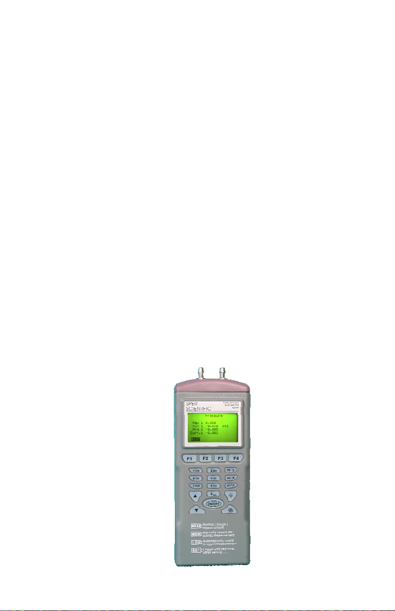
INTRODUCTION
This Manometer is ideal for measuring gauge pressure and
low differential pressure in clean rooms, test and balance,
medical equipment, HVAC, pneumatic
systems and computer peripherals.
Features a user-friendly interface with a large backlight
display, automatic data logging, measurement of single
and multiple points and a tripod mount.
The RS232 port, cable and software enable
communication with a
computer.
Powered by 4-AAA batteries (included), or an optional 9V
adaptor.
Gauge Pressure:
A measure of pressure in PSI that refers to ambient
pressure.
Differential Pressure: Measurement of the difference
between two pressures.
3
Page 4
View
previous/
next
record
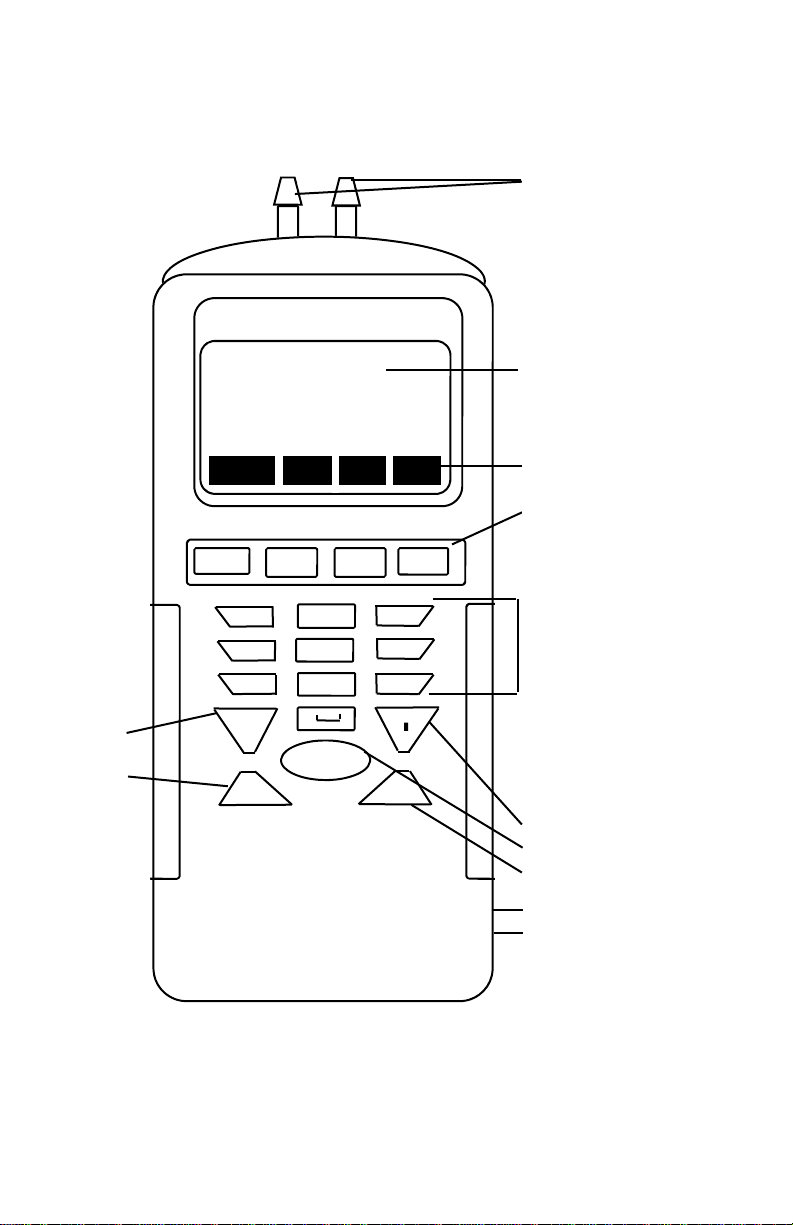
FRONT PANEL DESCRIPTION
Connectors
Welcome
MEAS MEM LOG SET
F1 F2 F3 F4
1 SYM. 2 ABC DEF 3
4 GHI 5 JKL MN0 6
7 PQRS 8 TUV WXYZ 9
0 ☼
▲
ON/OFF
▼
Display
On Screen prompts
correspond to the
F1-F4 buttons.
Keypad, press:
1 for 1*:$+-=,
2 for 2abcABC
3 for 3defDEF
4 for 4ghiGHI
5 for 5jklJKL
6 for 6mnoMNO
7 for 7pqrsPQRS
8 for 8tuvTUV
9 for 9wxyzWXYZ
0 for 0 and space
Backlight
On/Off
Not Applicable
DC 9V Adaptor Port
RS232 Port
4
Page 5
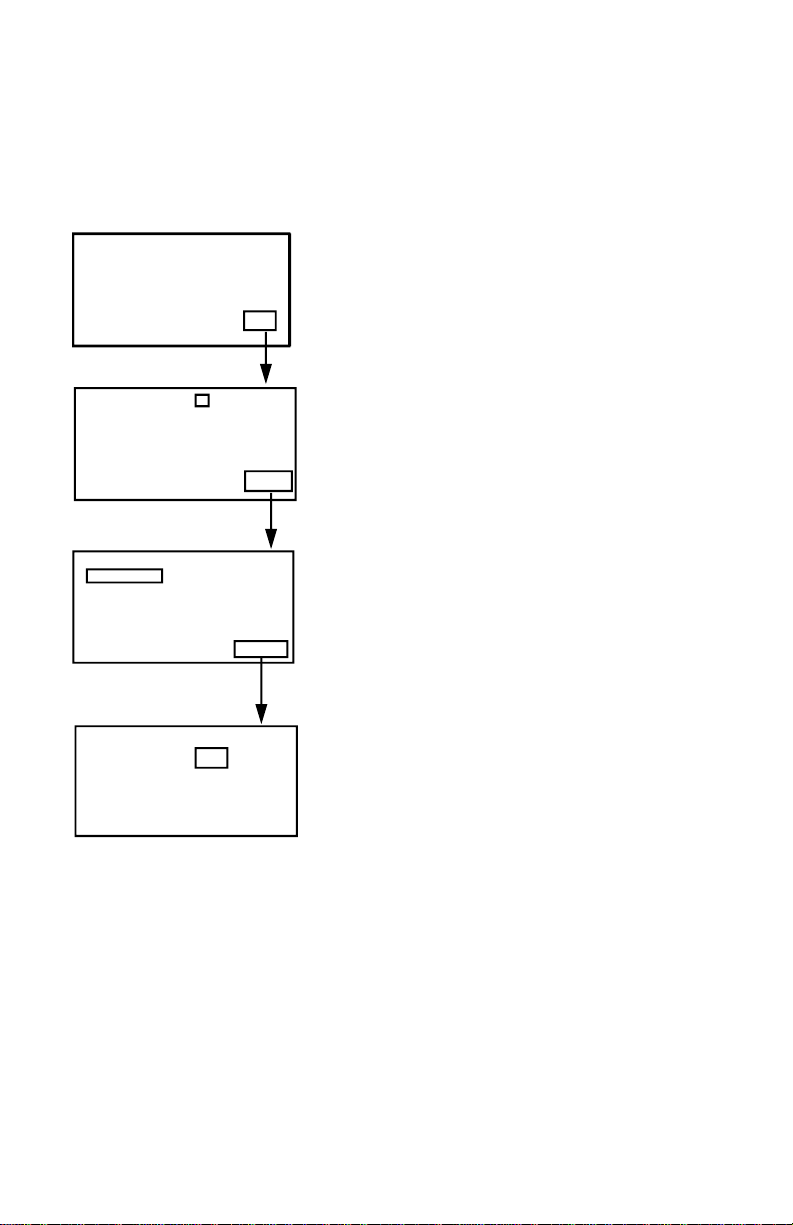
SET-UP PROCEDURE
Turn the meter on using the ON/OFF button. You will see
the Welcome menu shown below.
Welcome
MEAS MEM LOG SET
LCD Cont. (1-5): 3
Prn Cont. (1-9): 5
Auto Off: 20mins
Enable
EXIT EDIT NEXT
Set Clock:
MM-DD-YY HH:MM:SS
06-30-05 18 : 29 : 20
Set ID: Disable
ID: User Name
EXIT EDIT NEXT
1. Press F4 (SET) to enter the set-
up mode.
2. Use the ▲ or ▼ buttons to move
the on-screen cursor, F2 (EDIT),
and the Keypad to input chang-
es.
3. If changes are made, press the
F4 (Enter) button to save the new
settings or F1 (ABORT) to cancel
the change.
4. Press F4 (NEXT) to access the
next page.
Select Item
P psi
EXIT EDIT BACK
5. Press F1 (EXIT) to return to the
Welcome menu.
5
Page 6
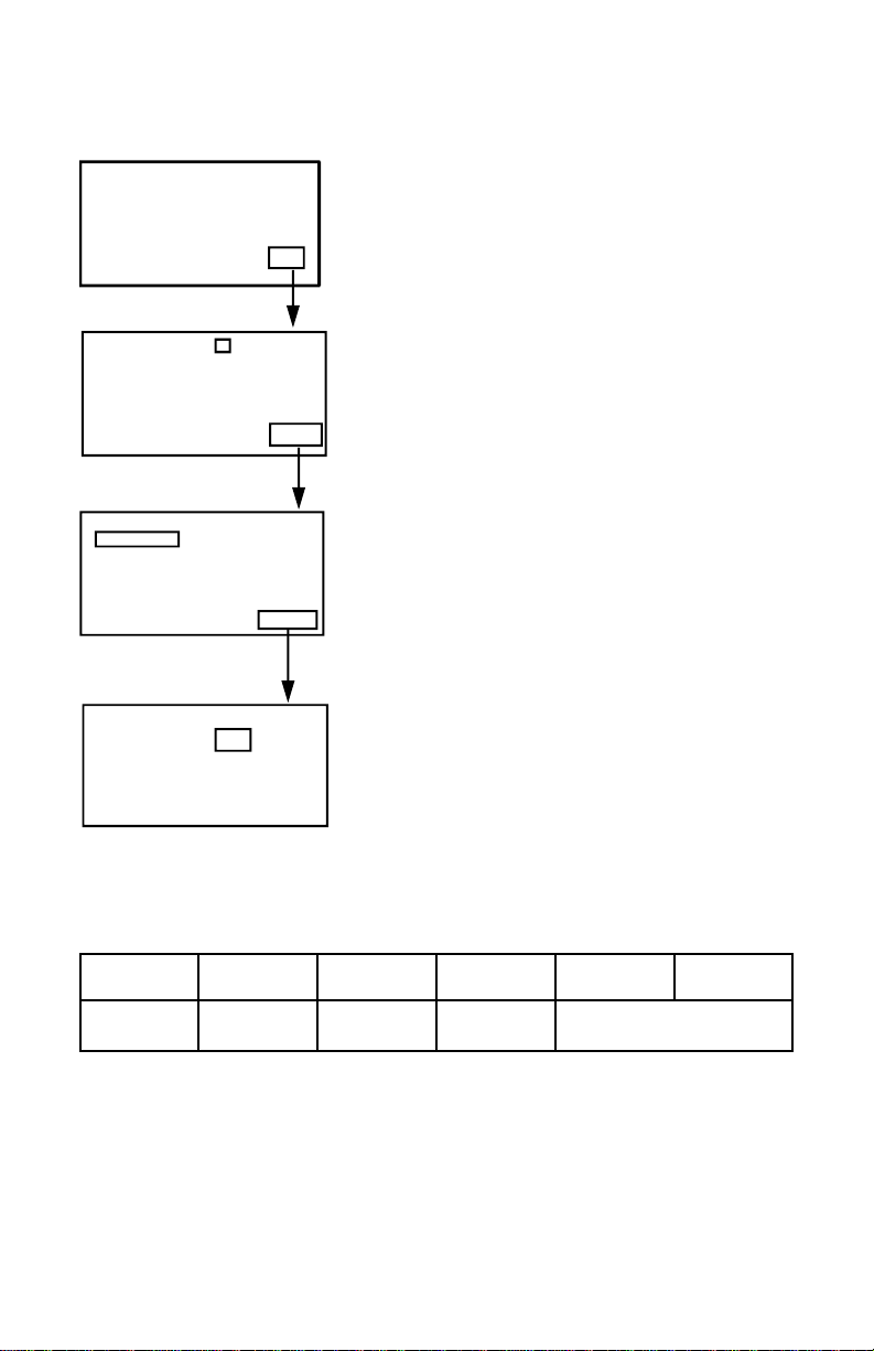
SET-UP PROCEDURE
Welcome
MEAS MEM LOG SET
LCD Cont. (1-5): 3
Prn Cont. (1-9): 5
Auto Off: 20mins
Enable
EXIT EDIT NEXT
Set Clock:
MM-DD-YY HH:MM:SS
06-30-05 18 : 29 : 20
Set ID: Disable
ID: User Name
EXIT EDIT NEXT
Select Item
P psi
EXIT EDIT BACK
1.LCD Cont. (1-5): Display con-
trast, 5 = least contrast.
2.Auto Off: 1~20 minutes, Enable/
Disable.
3.Set Clock: Select the date mode
MM-DD-YY, DD-MM-YY or
YY-MM-DD and set local time.
4.Set ID: Enable/Disable datalog-
ging.
5.ID: Alpha/numeric user name.
6.Select Item: Press F2 (EDIT) to
select X = not selected,
√ = selected.
7.Press the F2 (EDIT), ▲ or ▼
buttons to cycle through the 11
units of measure shown below:
PSI inH2 kPa ftH2 inHg cmH2
mbar bar mmHg ozin kgcm
6
Page 7

CALIBRATION
Calibration
1. Full (HI-LOW) calibration requires a standard manometer calibrator and should be performed by a professional
calibration laboratory. Contact Sper Scientific.
2. To perform a ZERO calibration, disconnect all tubes and
do not apply pressure to the connectors.
3. Press F1 (MEAS) followed by F3 (Cali) - “Calibration” is
displayed.
3. Press F4 (ZER0) and “Cali: 0.000 PSI” will be displayed.
4. Press F4 (ENTER) again - after approximately 3 se-
conds the meter will display “OK” to indicate that the
calibration was successful.
5. If NG (No Good) is displayed, perform the calibration
again. If the meter fails to calibrate after three (3)
attempts, it should be returned to Sper Scientific.
7
Page 8

MEASUREMENT PROCEDURES
Measurement Modes
The unit offers three (3) measurement modes:
1. F1 (MEAS) Single Measurement
2. F2 (MEM) Multiple Measurement
3. F3 (LOG) Auto Logging
Single Measurement
Welcome
MEAS MEM LOG SET
EXIT REC Cali
Max: 1.2psi
Min: -1.2psi
Avg: 0.4psi
Curr: 0.1psi
EXIT
P: 0.1 psi
Pressure
1. Ensure the tubing is connected
and not leaking or damaged.
2. Press F1 (MEAS) to take a
single pressure measurement.
3. Once a pressure is detected
the reading is displayed.
4. If desired, press F2 (REC) to
display the real-time Max., Min.
and Avg. pressure and last
pressure readings.
5. Press F1 (EXIT) to return to the
Welcome menu.
8
Page 9

MEASUREMENT PROCEDURES
Multiple Measurement
Manually record up to 99 data points with time & date and
your filename.
Welcome
MEAS MEM LOG
0.
P.
1
P.
02
P.
EXIT MEAS EDIT
0.1
0.
P.
1
P.
02
P.
EXIT CLR BACK
P. 0.100psi
ABORT SAVE
06:30:23:56:49
0.
1
P. 100psi
P.
02
P.
EXIT MEAS EDIT NEXT
06:30:23:56:49
0.
1
P. 100psi
P.
02
P.
EXIT CLR BACK
1. Press F2 (MEM) to enter Multiple Measurement mode.
2. Press F2 (MEAS) to take a measurement.
3. Once a pressure is detected the reading is displayed.
4. Press F4 (SAVE) to save the reading or press F1
(ABORT) to exit the current reading.
9
Page 10

MEASUREMENT PROCEDURES
5. By default, the first reading will be stored in memory
location 01: using the date & time as the filename. The
pressure reading is displayed next to the P: (for exam-
ple: 0.025 psi).
6. If desired, press F3 (EDIT) to edit the filename. Then,
use the Keypad to edit the filename. Cycle through the
characters by depressing the key until the desired character is highlighted. Once the filename has been de-
fined, press F4 (ENTER).
7. To take another reading, press the button to advance
to the next memory location and continue with the next
reading.
8. Press F1 (EXIT) to return to the Welcome menu.
10
Page 11

MEASUREMENT PROCEDURES
Clear Single Memory Record
1. Press F2 (MEM) to enter Multiple Measurement mode.
2. Use the ▲ or buttons to move to the desired memory
location.
3. Press F4 (NEXT) then press F2 (CLR). Once F2 is
pressed the “Clear ?” message is displayed. Press F2
(YES) again to clear the highlighted memory location or
F3 (NO) to cancel the clear function.
4. Press F1 (EXIT) to return to the Welcome menu.
Clear All Memory Records
1. Press F2 (MEM) to enter Multiple Measurement mode.
2. Press F4 (NEXT) then press F2 (CLR) for two (2) se-
conds. After two (2) seconds the “Clear All?” message
is displayed. Press F2 (YES) again to clear all 99
memory locations or F3 (NO) to cancel the clear func-
tion.
3. Press F1 (EXIT) to return to the Welcome menu.
11
Page 12

MEASUREMENT PROCEDURES
Run Auto Logger
Welcome
06-30 02:28:55
0.1 psi
MEAS MEM LOG SET
0023:
P:
0024:
P:
0025:
P:
EXIT START SET NEXT
1. Press F3 (LOG) to enter log
mode.
2. Press F3 (SET) to modify the us-
er-defined parameters.
0023: 06-30. 02:28:55
P: 0.1 psi
0024:
P:
0025:
P:
P-PG N-PG BACK
Begin: 30-06-06
Start: 02:28:06
End: 02-07-05
Suspend: 03:28:55
Rate: 60Sec(s)
Expect: 12000Point(s)
Remain: 11977Point(s)
EXIT EDIT VIEW NEXT
Begin: 30-06-06
Start: 02:28:06
End: 02-07-05
Suspend: 03:28:55
Rate: 60Sec(s)
Expect: 12000Point(s)
Remain: 11977Point(s)
START CLR BACK
Logging. . .
STOP MEAS VIEW
0023: 06-30 02:28:55
P: 0.100 psi
0024:
P:
0025:
P:
STOP MEAS ESC
3. Use the ▲ and buttons to se-
lect an auto log parameter and
press F2 (EDIT) to edit.
“Begin” date*
“Start” time
“End” date*
“Rate” (1 to 7200 seconds)
“Suspend” time
For 24 hour logging, set the Start
time to 00:00:00 and the Suspend time to 23:59:59.
“Expect” is the total number of
memory points (12,000).
Remain” shows the number of
available memory points (12,000
minus the number already
recorded).
ESC
P: 0.100 psi
* Ensure date formats are consistent
12
Page 13

MEASUREMENT PROCEDURES
4. Press F4 (ENTER) after modifying a parameter.
5. Once the parameters have been set press F4 (NEXT)
and F1 (START) to start the auto logger. The word
“Logging…” will be displayed.
The meter will automatically start and stop logging ac-
cording to your chosen parameters. Once the required
number of data points is reached, logging stops and the
records are held in the data logger.
6. During the auto logging press F2 (MEAS) to take a realtime reading or F4 (VIEW) to view memory record.
7. To stop auto logging press F1 (STOP).
8. Use the ▲ and buttons to scroll through the memory
records.
9. Press F4 (NEXT) to access the previous and next page
buttons. Press F1 (P-PG) or F2 (N-PG) to review previ-
ous or next 100 data points.
10. Press F4 (BACK) to access the auto log main menu and
press F2 (Start) to continue auto logging or F1 (EXIT).
13
Page 14

MEASUREMENT PROCEDURES
Clear Auto Log Data
1. Press F3 (LOG) to enter log mode.
2. Press F3 (SET) to enter auto log parameter set-up.
3. Press F4 (NEXT) to access the clear option.
4. Press F2 (CLR) for two (2) seconds and the “Clear All?”
message is displayed.
5. Press F2 (YES) to clear all auto log data, or F3 (NO) to
cancel clear function.
6. After clearing all auto log data, press F4 (BACK) to re-
turn to auto log parameter set-up.
7. Press F1 (EXIT) to return to the Welcome display.
ERROR CODES
E2: The value is under-range
E3: The value is over-range
E4: Error reading sample
AUTO POWER OFF
To prolong battery life, the meter will turn off automatically if
no buttons are pressed for your preset (1~20 minutes). To
edit or disable this feature, press F4 (SET) to access the
setup mode, then use the F2 (EDIT), ▲ or ▼ buttons and
Keypad to make changes.
14
Page 15

BATTERY REPLACEMENT
When the low battery icon is displayed, open the battery
cover, install 4-AAA Alkaline batteries and replace the cover. Remove the batteries during prolonged periods of nonuse.
840086 SPECIFICATIONS
Unit of Measure Range Resolution
PSI ±5 0.001
inH2O ±138 0.1
kPa ±34.5 0.01
ftH2O ±11.5 0.01
inHg ±10.2 0.01
cmH2O ±352 0.1
mbar ±345 0.1
Bar ±0.345 0.001
mmHg ±259 0.1
oz / inch2 ±80 0.01
Kg / cm2 ±0.35 0.001
Max Pressure 20 PSI
Accuracy
Repeatability ± 0.2% typ, max ± 0.5% fs
Combined linearity & hysteresis ± 0.29% typ, max ± 1.0% fs
Manual Memory 99
Auto Log Memory 1200
Battery 4-AAA Alkaline
Weight 9 oz (255g)
Dimensions 208x70x53 mm
15
± 0.3% fs @ 25 ºC
Page 16

840098 SPECIFICATIONS
Unit of Measure
PSI ±2 0.001
inH2O ±55.36 0.01
kPa ±13.79 0.01
ftH2O ±4.614 0.01
inHg ±4.072 0.01
cmH2O ±140.6 0.1
mbar ±137.9 0.1
Bar ±0.138 0.001
mmHg ±103.4 0.1
oz / inch2 ±32.48 0.01
Kg / cm2 ±0.141 0.001
Max Pressure 20 PSI
Range Resolution
840099 SPECIFICATIONS
Unit of Measure
PSI ±15 0.01
inH2O ±415.2 0.1
kPa ±103.4 0.1
ftH2O ±34.6 0.01
inHg ±30.54 0.01
cmH2O ±1054 1
mbar ±1034 1
Bar ±1.034 0.001
mmHg ±775.7 0.1
oz / inch2 ±240 0.1
Kg / cm2 ±1.055 0.001
Max Pressure 30 PSI
Range Resolution
16
Page 17

SOFTWARE CONFIGURATION
Use the included USB 2.0-P cable and software to download saved data to a PC for further analysis, or to upload
pre-edited filenames to save set-up time.
PC requirements: Win98 or above.
Main Menu Options (see Figure 1)
File
Mode
Port
Command
About
Main Menu Options
Figure 1.
Mode Menu Option
1. There are two (2) data modes: Memory and Logger.
2. Select the data mode from Mode on the main menu or
the drop-down menu. (see Figure 2)
3. In Logger mode, select “GoTo” to choose the logged data range you wish to display.
17
Page 18

SOFTWARE CONFIGURATION
Figure 2.
Com Port
1. Select the Com port and ensure that the meter is communicating with the PC.
2. The selected Com port is displayed in the bottom-left hand
corner of the software screen.
Com1
3. When connected, “PC Mode” and the Com port number
(1-8) are displayed on the meter.
Command Options
There are four (4) command options supported by the software. Choose the correct mode before uploading or downloading data. (see Figure 3)
1. Download Memory Data
2. Download Logger Data
3. Download All Data
4. Upload Memory Description
18
Page 19

SOFTWARE CONFIGURATION
Figure 3.
Print Options
Select the data to be printed from the following three (3)
choices: (see Figure 4)
1. All Data ( Memory and Logger Data printed in sequential
order).
2. Memory Data
3. Logger Data
ACCESSORIES
840089 Rubber Holster
840090 Water Resistant Pouch
840096 AC Adapter
19
Figure 4.
Page 20

Sper Scientific warrants this product against defects in materials
and workmanship for a period of ONE (1) year from the date of
purchase, and agrees to repair or replace any defective unit without
charge. If your model has since been discontinued, an equivalent
Sper Scientific product will be substituted if available. This warranty
does not cover probes, batteries, battery leakage, or damage
resulting from accident, tampering, misuse, or abuse of the product.
Opening the meter to expose its electronics will void the warranty.
To obtain warranty service, ship the unit postage prepaid to:
SPER SCIENTIFIC LTD
7720 E Redfield Rd, Suite 7
Scottsdale, AZ 85260
WWW.SPERSCIENTIFIC.COM
INFO@SPERSCIENTIFIC.COM
The defective unit must be accompanied by a description of the
problem and your return address. Register your product online or
return your warranty card within 10 days of purchase.
Revised 5/2/2012
 Loading...