

Page 1

Model UT30A: OPERATING MANUAL
Table of Contents (1)
Title
A. Introduction
B. Safety Rules
C. International Electrical Symbols
D. Feature
E. Specification
1. DC Voltage
2. AC Voltage
3. DC Current
4. AC Current
5. Resistance
6. Diode, Transistor,
Continuity Test
F. Operation Plate
1
Page
3
4
6
7
9
9
10
11
12
13
14
15
Page 2

Model UT30A: OPERATING MANUAL
Table of Contents (2)
Title
G. Make Measurements
1. DC Voltage Measurement
2. AC Voltage Measurement
3. DC Current Measurement
4. AC Current Measurement
5. Resistance Measurement
6. Diode measurement
7. Transistor hFE Measurement
8. Continuity test
9. “Hold”, “Power” Button
Function
H. Fuse and Battery replacement
I. Included Accessories
2
Page
16
17
19
20
22
23
25
27
28
29
30
31
Page 3

Model UT30A: OPERATING MANUAL
A. Introduction
UT30A Multimeter is 3 3/4 digits with steady operations, fashionable structure
and highly reliable hand-held measuring instrument. The meter can measure
DC/AC Voltage, DC/AC Current, Resistance, Diode, Transistor hFE, Continuity,
and etc. It is an ideal carry-on tool for users.
3
Page 4

Model UT30A: OPERATING MANUAL
B. Safety Rules(1)
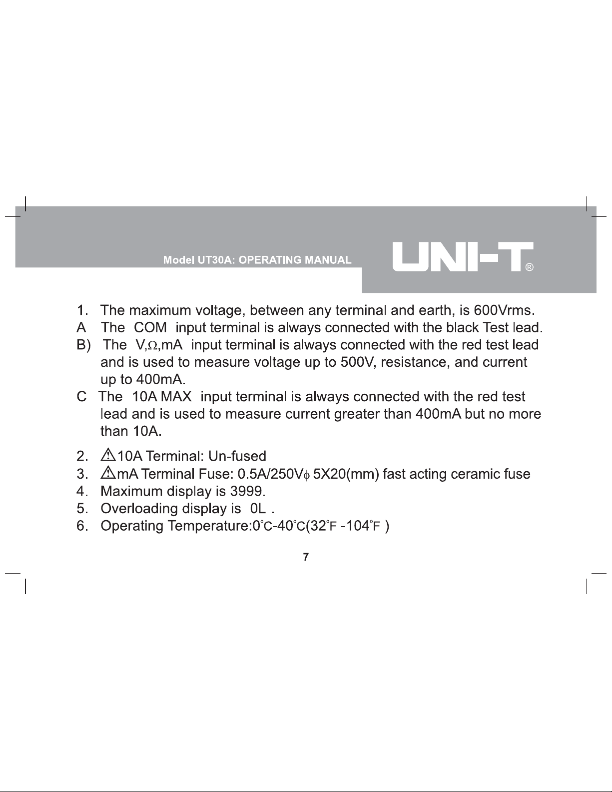
1. Read the manual carefully before use. Use the Meter only as specified
in this manual, otherwise, the protection provided by the Meter may
be impaired.
2. Do not operate the Meter unless the bottom case has been closed as
terminal can carry voltage.
3. Inspect the insulation of the test leads and no damages to the test
leads before using the Meter.
4. As soon as the battery indicator’s “ ” appears, replace the battery to
ensure accurate readings.
5. Set the Meter to suitable function and range before each measurement.
6. Tested values over the maximum range of each measurement can
cause damages of the Meter or electric shock to users.
7. Do not turn the rotary switch during measurement to avoid damages
of the Meter.
4
Page 5

Model UT30A: OPERATING MANUAL
B. Safety Rules(2)
8. When measuring voltage higher than DC 60V or AC 30Vrms, pay extra
attention to avoid electric shock.
9. Use only 0.5A/250V φ 5X20(mm) fast acting ceramic fuse to replace
the bad one.
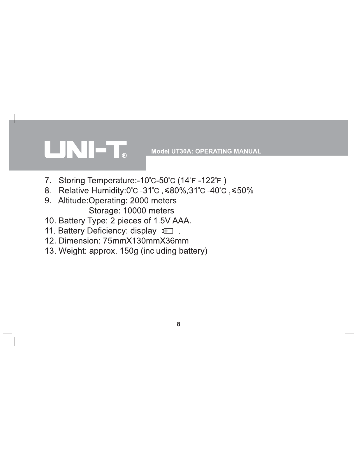
10. Do not operate or store the Meter under high temperature or humid
condition, otherwise, the Meter will get worse.
11. Do not change internal circuit to avoid damages to the meter and
danger to the user.
12. Periodically wipe the case with cloth and mild detergent. Do not use
abrasives and solvents.
5
Page 6

Model UT30A: OPERATING MANUAL
C. International Electrical Symbols
AC or DC
AC (Alternating Current)
DC (Direct Current)
Grounding
Double Insulated
Deficiency of Built-In Battery
Diode
Fuse
Continuity Test
Safety Rules
CAUTION-FOR CONTINUED PROTECTION AGAINST FIRE, REPLACE
ONLY WITH FUSE OF THE SPECIFIED VOLTAGE AND CURRENT
RATINGS.
6
Page 7
D. Feature(1)
“
“
“
”
”
”
”
“
Page 8
D. Feature(2)
”
“
Page 9

1. DC Voltage
Model UT30A: OPERATING MANUAL
E. Specification(1)
Range
400mV
4V
40V
400V
500V
Resolution
0.1mV
1mV
10mV
100mV
1V
Accuracy
(0.8%+3)
(0.8%+1)
(1%+3)
9
Page 10
E. Specification(2)
Page 11

3. DC Current
Model UT30A: OPERATING MANUAL
E. Specification(3)
Range
400µA
4mA
40mA
400mA
10A
Resolution
0.1µA
1µA
10µA
100µA
10mA
Accuracy
(1%+2)
(1.2%+2)
(1.5%+2)
Overload Protection: 0.5A/250v fuse. Un-fuse at 10A, measuring time
limit is equal or less than 10 seconds, and time interval should be
equal or over 15 minutes.
Measuring voltage drop: Full range is 400m V.
11
Page 12

4. AC Current
Model UT30A: OPERATING MANUAL
E. Specification(4)
Range
400µA
4mA
40mA
400mA
10A
Resolution
0.1µA
1µA
10µA
100µA
10mA
Accuracy
Overload Protection: 0.5A/250V fuse. Un-fuse at 10A; measuring time
limit is equal to or less than 10 seconds; time interval is equal or over
15 minutes.
Voltage drop: 400mV for full range.
Frequency response: 40Hz-400Hz
Display: RMS of Sine Wave Value (Average Value)
12
(1.3%+5)
(2%+5)
Page 13

5. Resistance
Model UT30A: OPERATING MANUAL
E. Specification(5)
Range
400Ω
4kΩ
40kΩ
400kΩ
4MΩ
40MΩ
Resolution
0.1Ω
1Ω
10Ω
100Ω
1KΩ
10KΩ
Accuracy
(1.2%+2)
(1%+2)
(1.2%+2)
(1.5%+2)
Overload Protection: All ranges are 230V (DC/ AC current).
13
Page 14

Model UT30A: OPERATING MANUAL
E. Specification(6)
6. Diode, Transistor, Continuity Test
Function
Diode
Transistor
Continuity
Test
Range
hFE
Resolution
1mV
1β
0.1Ω
Input
Protection
230V DC
or AC
230V DC
or AC
Overload Protection: 230V (DC/ AC current)
14
Remark
3V when open circuit
Ibo 10µA Vce 3V
The buzzer beeps
when the value is less
than 80
Page 15

Model UT30A: OPERATING MANUAL
F. Operation Plate
1. Liquid Crystal Display
2. Data hold or POWER function Button
3. Rotary Switch
4. Transistor Test Jack
5. Common Input Jack
6. 10A Input Jack
7. V
ΩmA Input Jack for General
Measurement
( figure 1)
15
Page 16

Model UT30A: OPERATING MANUAL
G. Make Measurements(1)
First, set rotary switch to proper position, after several seconds of selfcheck, the meter will enter measuring state. When “ ” appear on LCD,
replace a new battery to ensure accurate display.
Second,
symbol beside the input jack, warns you when testing current
and voltage, input values must not exceed the limit.
16
Page 17

Model UT30A: OPERATING MANUAL
G. Make Measurements(2)
1. DC Voltage Measurement (figure 2)
1) Never measure voltage value exceeding 500V, although it is possible
to get the reading, which will cause damages to the internal circuit and
hurt users;
2) Measuring value input from “V
mA” (red test lead) and “COM”
Ω
(black test lead.)
3) The Meter has auto-range function
with initial range 400mV, at which,
the meter may display irregular
digits for open Circuit, and come
to ZERO for short circuit, which
are both normal.
17
( figure 2 )
Page 18

Model UT30A: OPERATING MANUAL
G. Make Measurements(3)
4) For ranges except 400mV, input impedance 10M
Ω, this can cause
measuring tolerance at high impedance circuit ,If circuit impedance
is equal or less than 10kΩ, you can ignore the tolerance (0.1% or lower).
5) The meter would clatter with flash of LCD reading if input exceeding
1000V, which warns you should pay extra attention.
18
Page 19

Model UT30A: OPERATING MANUAL
G. Make Measurements(4)
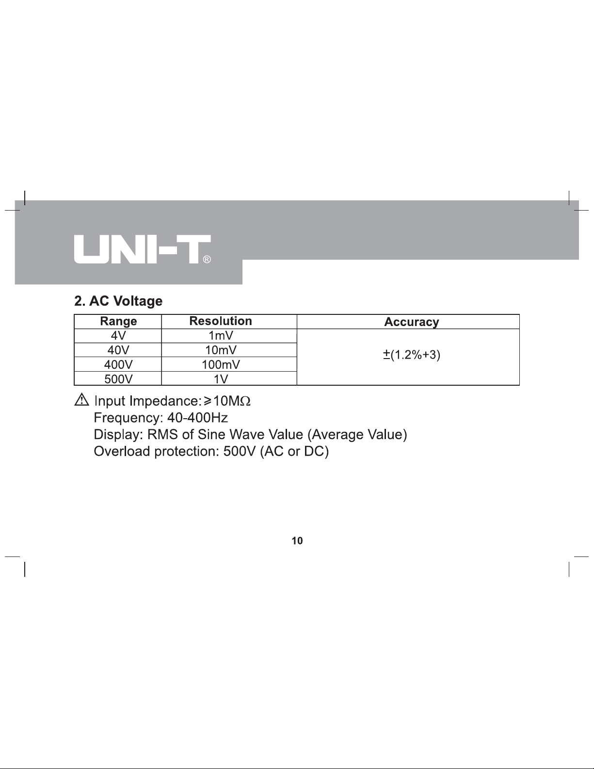
2. AC Voltage Measurement
(figure 3)
Same as DC voltage measurement, however, the meter has auto-range
function with initial range of 4V, and input exceeding 750V would make it
clatter with LCD glittering, which warns you should pay extra attention.
(figure 3)
19
Page 20

Model UT30A: OPERATING MANUAL
G. Make Measurements(5)
3. DC Current Measurement
(figure 4)
1) This range is manual range. Do not measure, when value between
open voltage and earth exceeding safety voltage 60V, to avoid
damages to the Meter or to the instruments under test, and hurt the
user.
2) Before measurement, cut off
the power of object to be
measured and inspect whether
input terminal or rotary switch
is set to the proper range.
Ensure it is proper, and then
you can measure the object
with power on.
(figure 4)
20
Page 21

Model UT30A: OPERATING MANUAL
G. Make Measurements(6)
3) If the magnitude of current is unknown, you should set rotary switch
to the higher range, then adjust to a lower range until a satisfactory
reading is obtained.
4) Measuring value inputs from “V
mA” or “10A” jack (red test leads)
and “COM” jack (black test leads).
5) For “V
mA” input jack, the Meter has 0.5A/250V ( 5x20mm) ceramic
fuse overload protection, if overloaded, the fuse will burn up, so replace
with a new one with the same specification.
6) For 10A input jack, it is unfused. For your safety, every measuring time
should equal to or less than 10 seconds, times interval should be equal
to or over 15 minutes.
7) The meter would clatter with glitter of LCD reading if input exceeding
1000V or overloaded, which warns you pay extra attention.
21
Page 22

Model UT30A: OPERATING MANUAL
G. Make Measurements(7)
4. AC Current Measurement
(figure 5)
Same as DC current measurement.
(figure 5)
22
Page 23

Model UT30A: OPERATING MANUAL
G. Make Measurements(8)
5. Resistance Measurement
(figure 6)
1) To avoid damages to the Meter, when measuring resistance, cut off the
power of the object and no charge in capacitor.
2) Measuring value inputs from “VΩ mA” jack (red test leads) and “COM”
jack (black test leads).
(figure 6)
23
Page 24

Model UT30A: OPERATING MANUAL
G. Make Measurements(9)
3) Wires takes 0.1Ω -0.3Ω tolerance at function of 400Ω when measuring
resistance. To get an accurate reading, you can subtract the short
circuit values of the 2 test leads.
4) It will take several seconds for the display to become stabilize when
resistance value is over 1MΩ, it is normal, because it is auto-range.
24
Page 25

Model UT30A: OPERATING MANUAL
G. Make Measurements(7)
6. Diode measurement (figure 7)
1) Cut off the power supply of the object to avoid damages to the Meter
when measuring diode, no charge in capacitor.
2) Measuring value inputs from “V
jack (black test leads).
( figure 7)
Ω mA” jack (red test leads) and “COM”
25
Page 26

Model UT30A: OPERATING MANUAL
G. Make Measurements(8)
3) When measuring voltage drop of PN, for a good silicon semiconductor
structure, normal positive reading should stay between 0.5V~0.8V.
Negative display being “OL” means open circuit; at this time, the red
test lead is positive pole, and the black one is negative pole. In addition,
“V” acts as unit of this range.
26
Page 27

Model UT30A: OPERATING MANUAL
G. Make Measurements(9)
7. Transistor hFE Measurement
(figure 8)
1) Check that the transistor is PNP or NPN type at first.
2) Connect the transistor to be measured to the corresponding jacks.
3) LCD displays hFE reference value.
4) Measuring condition: Ib 10
µA, Vce 3V
( figure 8)
27
Page 28

Model UT30A: OPERATING MANUAL
G. Make Measurements(10)
8. Continuity test
(figure 9)
Before testing continuity, power off and no charge in capacitor to avoid
damages to the Meter. Measuring value inputs from “VΩ mA” jack (red test
lead) and “COM” jack (black
test lead). If the impedance
of measured circuits is equal
or less than 80Ω, the Meter
would clatter, it means the
circuit is close. Display on
LCD is circuit resistance.
(80
Ω is a dividing value for
OPEN or CLOSE.)
( figure 9)
28
Page 29

Model UT30A: OPERATING MANUAL
G. Make Measurements(11)
9. “Hold”, “Power” Button Function
1) Pressing “Hold” button holds current reading displayed on LCD in
open state, press it again to release the current reading displayed on
LCD.
2) At power on state, press Hold to enter and exit the touch hold mode.
3) At hold mode, it can capture the present reading and display on the
LCD; otherwise, the reading is a random value.
4) The Meter has Auto-power-off function, which switches the Meter off
if it is not used for more than 30 minutes. At this time, press the button
will restart the power.
Hold and power Button are the same one.
29
Page 30

Model UT30A: OPERATING MANUAL
H. Fuse and Battery replacement
1. Remove inputs & test leads from terminals.
2. Remove two rubber feet and two screws from the bottom case.
3. Separate the case bottom from the case top.
4. Replace the battery or fuse with the identical type and specification as
stated on this operating manual.
5. Rejoin the case bottom and case top, and reinstall two screws and
two rubber feet.
(figure 10)
30
Page 31

Model UT30A: OPERATING MANUAL
I. Included Accessories
1. Operating Manual
2. Test Leads
3. 2 pieces of 1.5V (AAA) Battery
31
Page 32

Model UT30A: OPERATING MANUAL
~ END ~
* The manual is subject to changes without separate notice. *
32
 Loading...