

Page 1

SPER
Advanced Light Meter
840022
Instruction Manual
SCIENTIFIC
LTD.
Page 2

TABLE OF CONTENTS
1. INTRODUCTION .............................................................................. 2
2. PANEL DESCRIPTION .................................................................... 3
3. OPERATING INSTRUCTIONS
3-A. General Measurement .......................................................... 4
3-B. Hold ....................................................................................... 4
3-C. Peak Hold .............................................................................. 4
3-D. Record Maximum / Minimum .............................................. 4-5
3-E. Notes and Precautions ........................................................ 5
4. ZERO ADJUSTMENT AND CALIBRATION ................................... 5
5. BATTERY REPLACEMENT ............................................................ 5
6. RS232 SERIAL INTERFACE ........................................................... 5-6
7. SPECIFICATIONS ........................................................................... 6-7
8. WARRANTY ..................................................................................... 8
1. INTRODUCTION
Monitor light levels anywhere with fast, stable and accurate response.
Results are easily read on the extra large LCD with bar graph. Measures
Foot Candles or Lux and offers high resolution, 5 ranges, selectable light
source types (Tungsten, Fluorescent, Sodium or Mercury), max-min, peak,
hold, RS232 output, zero adjustment, a tripod back, automatic power off,
low battery and out of range indicators. The sensor is cosine and color
corrected and hermetically sealed to ensure long term stability.
Comes ready to use with a 9V battery, instructions, carrying case, and a
detachable sensor with cover for easier replacement or repair.
- 2 -
Page 3
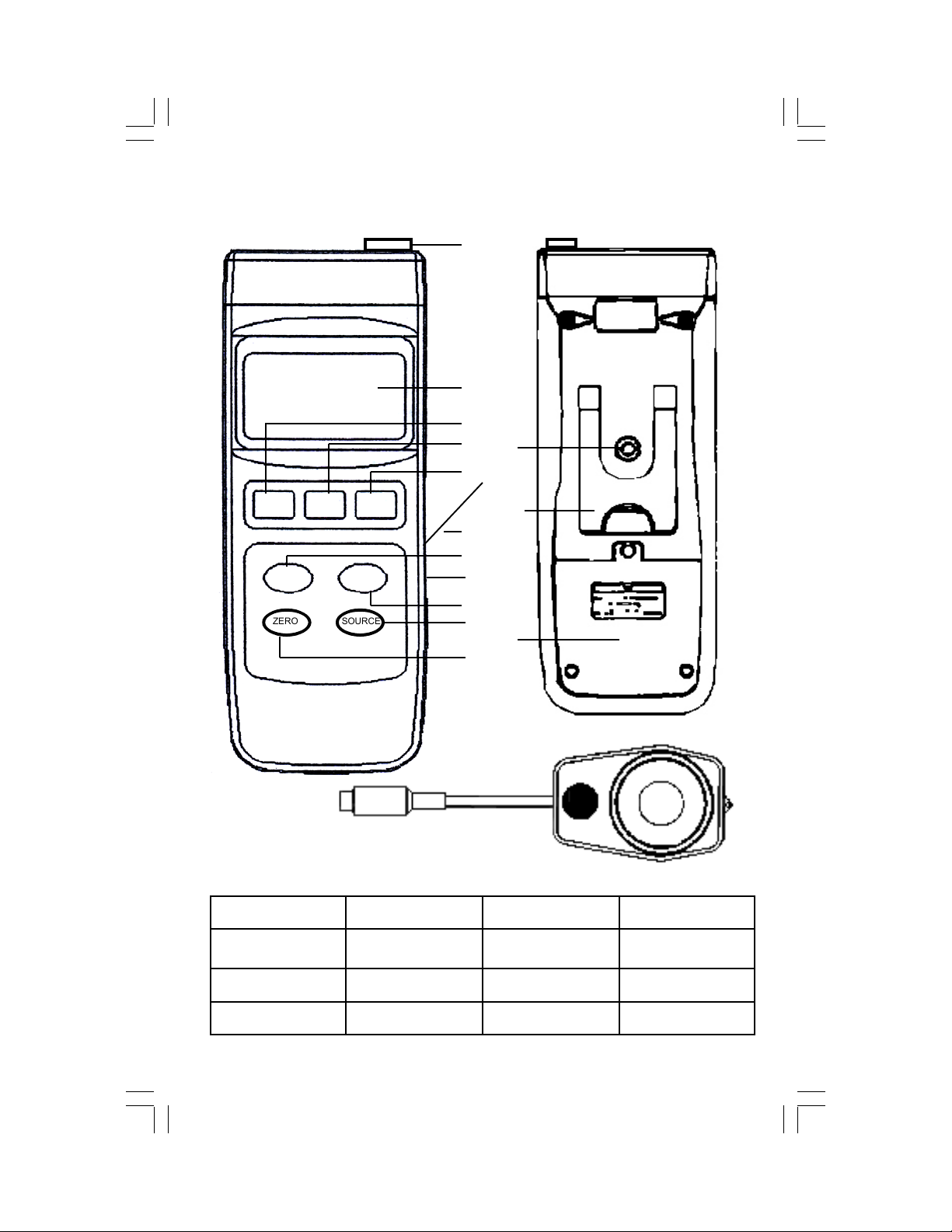
2. PANEL DESCRIPTION
POWER HOLD
Lux/Fc RANGE
ZERO SOURCE
REC.
MAX/MIN
1
2
3
4 12
5
13
6
7
8 (side)
9
10
14
11
15 16
1. Sensor Input 2. Display 3. Power Button 4. Hold Button
5. REC. MAX/MIN
Button
9. Range Button 10. Source Button 11. Zero Button 12. Tripod Screw
13. Stand 14. Battery Cover 15. Sensor Plug 16. Photo Sensor
6. RS232 Cover (lifts) 7. Lux/FC Button 8. RS-232 Output
(see 6)
- 3 -
Page 4

3. OPERATING INSTRUCTIONS
3-A. General Measurement
• Insert the SENSOR (15) plug into the SENSOR INPUT (1) and turn the
meter on by pressing the POWER (3) button.
• Remove the lens cap from the PHOTO SENSOR (16) .
• Select the desired unit of measure by pressing the LUX/FC (7) button.
• Select the lighting type by pressing the SOURCE (10) button. The display
shows “Hg” for Mercury, “Na” for Sodium, and “FL” for Fluorescent Lamp.
For Tungsten and unknown sources use the standard mode - no indicator
appears on the screen.
• Select the maximum range by pressing the RANGE (9) button. If the out
of range indicator "- - - - " appears, select another range or discontinue
use. For the highest accuracy, select the range that offers the highest
resolution (most number of digits after the decimal point).
• Point the PHOTO SENSOR (16) toward the source and read the
results on the display.
• The instrument has an automatic shut off function in order to prolong
battery life. After approximately 10 minutes without activity (no buttons
pushed), the meter will automatically shut off. To disable this feature,
press the REC MAX/MIN (5) button.
• Press the POWER (3) button to manually turn the meter off.
3-B. Hold
• During measurement, press HOLD (4) to freeze the measured value.
• "HOLD" and the value are displayed.
• Press the HOLD (4) button again to exit
.
3-C. Peak Hold
• During measurement, press the HOLD (4) button for 2 to 3 seconds.
• “Peak HOLD” and the peak value are displayed and updated if exceeded.
• To erase the peak value, press the HOLD (4) button once (the display will
flash).
• To exit this function, press the HOLD (4) button for at least 2 seconds.
3-D. Record Maximum / Minimum
• Press the REC MAX/MIN (5) button once to enter the recording mode.
"REC" and the recorded values are displayed and continuously updated.
• Press the REC MAX/MIN (5) button as needed to view the recorded Max
and Min values. "REC Max" and the maximum recorded value or "REC
Min" and the minimum recorded value are displayed.
• Note: The Max/Min values are frozen and not updated until the meter
returns to recording mode.
- 4 -
Page 5

• To return to recording mode, press the HOLD (4) button. "REC" is
displayed without "Max" or "Min".
• To erase the recorded Max/Min values and exit the recording mode,
press the REC MAX/MIN (5) button for at least 2 seconds.
Notes and Precautions
3-E.
• Avoid range overload.
• When using PEAK HOLD (3-C) or REC MAX/MIN (3-D) your
measurements must be within the selected range, if not, the out of
range indicator "- - - -" will be displayed.
• Cover the PHOTO SENSOR (16) with the sensor cap when the meter
is not in use.
• Fluctuations in the reading are often due to shadows or a weak battery. Also, ambient temperatures and drafts may affect the reading.
• Do not store in areas of high temperature and/or humidity.
• Remove the battery for long-term storage.
• Do not adjust the calibration trimmer beneath the RS232 Cover (6).
4. ZERO ADJUSTMENT AND CALIBRATION
• With the sensor cover securely in place and the meter turned on, use
the RANGE (9) button to select the 40.00 Lux range (digits appear).
• Press the ZERO (11) button and the "0.00
LUX" should be displayed.
• To maintain accuracy, annual laboratory calibration is recommended
and available from Sper Scientific.
5. BATTERY REPLACEMENT
• Replace the battery when the low battery icon is displayed.
• In-spec measurements may be made for several hours after the low
battery indicator appears.
• Remove the BATTERY COVER (14) screw and slide the cover off.
• Replace the battery with a fresh 9V battery (alkaline or heavy duty).
6. RS232 PC SERIAL INTERFACE
Use a small screwdriver to gently lift the RS232 COVER (6) up to expose
the RS232 OUTPUT (8) 3.5 mm terminal. The signal output is a 16-digit
data stream that can be adapted to user-defined applications. A RS232
lead with the following connection is required to link the instrument with the
PC serial interface.
Meter (3.5 mm jack plug) PC (9W ‘D” Connector)
Center Pin .................................. Pin 4 Pin 2 2.2 K
Ground/shield ............................ Pin 2 Pin 5 resistor
- 5 -
Page 6

The 16 digits data stream will be displayed in the following format:
D15 D14 D13 D12 D11 D10 D9 D8 D7 D6 D5 D4 D3 D2 D1 D0
Each digit indicates the following status:
D0 End Word
Display reading, D1 = LSD, D8 = MSD
D1 & D8
E.g: If the display reading is 1234, then D8 to D1 is:
00001234
D9
Decimal Point (DP), position from right to the left
0 = No DP, 1= 1 DP, 2 = 2 DP, 3 = 3 DP
D10 0 = Positive 1 = Negative
D11 & D12
Annunciator for Display
Lux = 15, Ft-cd = 16
D13 The upper display data = 1, The lower display data = 2
D14 4
D15 Start Word
RS232: 9600, N, 8, 1
SPECIFICATIONS
Display
Large 2” x 1.5” (52 mm x 38 mm), 5 digit
display with bar graph indicator.
"- - - -" appears at the top of the display for
Out of Range Indicator
over-range, or at the bottom of the display for
under-range.
Operating Environment 32 ~ 122°F (0 ~ 50°C), Less than 80% RH
Weight 9.9 oz (280g)
Dimensions
Optional Accessories
Main Unit: 7.9 x 2.7 x 1.2" (200 x 68 x 30mm)
Sensor: 3.2 x 2.2 x 0.3" (82 x 55 x 7mm)
Sensor Lead: Extends to appx. 3½ ft
840057 - RS232 Cable
840094 - RS232 to USB Adaptor Cable
840090 - Water Resistant Instrument Pouch
840092 - Bench-Top Tripod
840093 - Field Tripod
850080 - Software
- 6 -
Page 7

Unit of
Measure
Range In-Range Display Res. Accuracy
40.00 0 ~ 40.00 0.01
400.0 36.6 ~ 400.0 0.1
±(3% rdg + 0.5% F.S.)
4,000 360 ~ 4,000 1
Lux
40,000 3,600 ~ 40,000 10
400,000
10,000 ~
400,000
100
<100,000 ± (3% rdg +
0.5% F.S.). >100,000
for reference only
4.000 0 ~ 3.720 0.001
40.00 3.35 ~ 37.20 0.01
±(3% rdg + 0.5% F.S.)
Foot
Candle
400.0 33.5 ~ 372.0 0.1
4,000 335 ~ 3,720 1
< 9,300 ± (3% rdg +
40,000 930 ~ 37,200 10
0.5% F.S.). >9,3000
for reference only
Accuracy tested by a standard parallel light, tungsten lamp of 2856°K.
LIGHT SPECTRUM CHART
120
100
80
60
40
20
0
410
430
450
470
490
510
530
550
570
590
610
630
650
670
690
710
730
SPER CEI
750
- 7 -
Page 8

8. WARRANTY
Sper Scientific warrants this product against defects in materials and
workmanship for a period of five (5) years from the date of purchase,
and agrees to repair or replace any defective unit without charge. If
your model has since been discontinued, an equivalent Sper Scientific
product will be substituted if available. This warranty does not cover
probes, batteries, or damage resulting from accident, misuse, or abuse
of the product. To obtain warranty service, ship the unit postage
prepaid to:
The defective unit must be accompanied by a description of the
problem and your return address. Register your product online or
return your warranty card within 10 days of purchase.
SPER SCIENTIFIC LTD
7720 E Redfield Rd, Suite 7
Scottsdale, AZ 85260
WWW.SPERSCIENTIFIC.COM
INFO@SPERSCIENTIFIC.COM
Rev. 9/22/06
- 8 -
 Loading...