

Page 1

Laser Power Meter
840017
Instruction Manual
SPER
SCIENTIFIC LTD.
Page 2
CONTENTS
I. Introduction ..................................................................................... 2
II. Meter Description ............................................................................ 2
III. Operating Instructions
Measuring Procedures ............................................................. 3
Precautions ............................................................................... 4
IV. Specifications .................................................................................. 4
V. Warranty .......................................................................................... 4
I. INTRODUCTION
Your new Laser Power Meter provides a fast and accurate way to measure
laser beam power from 635nm ~ 830nm. Features a built-in stand for
stability during use.
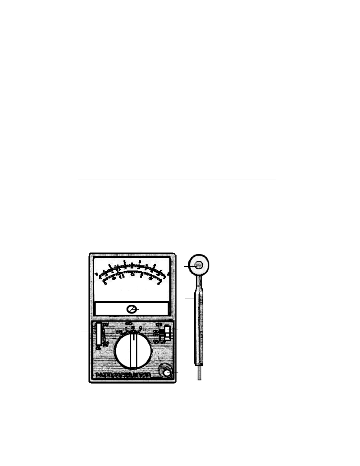
II. METER DESCRIPTION
2
4
5
3
7
- 2 -
8
1
6
1. Wavelenth selector
2. nm fine-tuner
(red wheel)
3. Zero adjustment
4. mW indicator panel
5. Optical power selector
6. Photosensor input
7. Photosensor head
8. Photosensor handle
Page 3

III. OPERATING INSTRUCTIONS
MEASUREMENT PROCEDURES
Insert the probe’s plug into the Photosensor Input and uncover the Photosensor Head.
Zero Adjustment: Slide the Wavelength Selector to CAL ADJ. Turn the
Optical Power Selector to 1 mW. If the unit does not indicate a zero read-
ing, use a small screwdriver to turn the Zero Adjustment until the needle
rests on “0”.
Wavelength Selector: There are 4 settings: ,635nm and 650nm for visible
beams, 830nm for ultra red beams, and CAL ADJ. Select the appropriate
setting for your application.
If the beam wavelength is other than 635nm, 650nm or ;830nm, slide the
Wavelength Selector to CAL ADJ position and adjust the red nm FineTuner wheel to obtain your reading. The meter is calibrated to 635nm,
650nm and 830nm. Readings obtained using the CAL ADJ setting are for
reference only - accuracy is not guaranteed.
Optical power selector: There are 4 settings, 0.3mW, 1mW, 3mW, and
5mW. Start with 5mW and turn the selector counter clockwise to locate the
setting with the highest accuracy for your application.
The mW indicator panel displays the reading. There are three scales on
the panel. The 0.3mW setting uses the 3mW scale, but the actual measurement is 1/10th of reading (divide results by 10).
Direct the laser beam in a straight line onto the center of the Photosensor
Head. Place the laser light source the same distance as it would be during
use. For example, if the laser beam is normally directed onto an object that
is 3 inches away, place the Photosensor Head 3 inches from the laser light
source. When measuring ultrared laser light, move the laser slightly while
focusing on the Photosensor Head until you receive the highest readout.
Note: When measuring a weak beam in a darkened environment, an ambient light source (such as a desk lamp) can cause measurement errors.
- 3 -
Page 4

PRECAUTIONS: When not in use, cover the Photosensor Head to keep the
lens clean. Measurement errors may occur if the lens becomes dirty. As
needed, use an alcohol swab to clean the surface. Protect your instrument
from water, shock, dust, heat and sunlight.
Laser light can be harmful to the eyes and/or skin, avoid exposure to the
beam and do not look directly into the light. Do not aim the light at the eyes of
other humans or animals. Do not aim the laser light into a mirror or reflective
surface where the light could be reflected into your eyes.
IV . SPECIFICATIONS
Wavelength beam range 635nm ~ 830nm
Beam power range 0.1mW ~ 5mW
Beam power selector 0.3mW, 1mW, 3mW, 5mW
Power Source No batteries required as the meter
obtains power from the laser itself
Accuracy 1, 5mW+5% 0.3, 3mW+10%
for the 3 specific wavelengths
Photosensor Silicone photo diode
(sensor diameter 9mm)
Photosensor dimension 1”(D) x 4 3/4”(L)
23.5mm(D) x 120.5mm(L)
Approximate probe length 42” (1 meter)
Device dimension 5 3/4”(L) x 3 3/4”(W) x 1 1/2”(H)
14mm(L) x 98mm(W) x 35mm(H)
5 YEAR METER WARRANTY
Sper Scientific warrants this product against defects in materials and workmanship for a period of five (5) years from the date of purchase, and agrees
to repair or replace any defective unit without charge. If your model has since
been discontinued, an equivalent Sper Scientific product will be substituted if
available. This warranty does not cover damage resulting from accident, misuse, or abuse of the product. In order to obtain warranty service, ship the unit
postage prepaid to:
SPER SCIENTIFIC LTD.
7720 East Redfield, Suite 7, Scottsdale, Arizona 85260
(480) 948-4448, info@sperscientific.com, www.sperscientific.com
Include a brief description of the problem along with your contact information.
Be sure to return your warranty card or register online within 10 days.
Rev 08/20/04
- 4 -
 Loading...