

Page 1

Detachable Probe Sound Meter
SPER
SCIENTIFIC
840012
Instruction Manual
LTD.
Page 2

CONTENTS
1. Introduction ............................................................................. 3
2. Meter Description .................................................................... 3
3. Operating Instructions
3-A Measuring Procedures .................................................. 4
3-B Hold ............................................................................... 4
3-C Rec. Max/Min ................................................................. 4-5
3-D Max. Hold ...................................................................... 5
3-E Signal Output ................................................................. 5
3-F Calibration ..................................................................... 5
3-G Precautions .................................................................... 5
3-H Auto Shut Off ................................................................. 6
3-I Battery Replacement ..................................................... 6
3-J RS232 PC Serial Interface ............................................ 6
4. Specifications .......................................................................... 7
5. Frequency Weighting (A and C) Characteristics ..................... 8
6. Warranty .................................. ....................... ..................... .... 8
- 2 -
Page 3
1. INTRODUCTION
Features a detachable probe for easy replacement, and both RS232
computer interface and AC outputs. Also has A and C decibel frequency weighting scales, fast or slow time weighting, and two hold
functions. Meets IEC651 and ANSI S1.4 specifications for a type 2
sound meter. Covers 30~130 dB in both Manual and Auto ranging
scales with 0.1 dB resolution and an accuracy of ±1.5 dB. Calibrate in
compliance with OSHA using Acoustical Calibrator 840031 or equivalent. Has a fold-out easel back and a tripod screw.
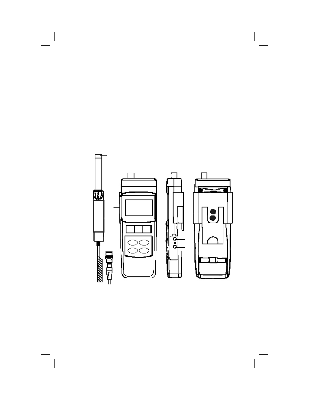
2. METER DESCRIPTION
1
5
6
2
3
7 8 9
10 11
12 13
4
14
15
16
17
18
1. Microphone
2. Probe Holder
3. Probe Handle
4. BNC Plug
5. BNC Socket
6. LCD display
7. Power Button
8. Hold Button
9. Rec./Max./Min
10. Max. Hold Button
11. A/C Button
12. Fast/Slow Button
- 3 -
13. Range Button
14. AC Output
15. Cal. Adjustment
16. RS232 Output
17. Easel
18. Battery
Page 4

3. OPERATING INSTRUCTIONS
3-A. MEASURING PROCEDURES - See section 2, page 3 for button
locations and descriptions.
• Connect the BNC PLUG (4) to the BNC SOCKET (5).
• Slide the PROBE HANDLE (3) into the PROBE HOLDER (2) (opt).
• Press the POWER (7) button to turn the unit on.
• The default mode is: Auto range, “A” frequency weighting and Fast
time weighting.
• To change the frequency weighting, press the A/C (11) button.
• The "A" frequency weighting simulates human ear response. For
an environmental sound measurement, select the "A" weighting.
• The "C" weighting approximates a flat response. Often, "C" is
used to check the noise of machinery where the target sound level
is already known.
• For more information about Frequency Weighting Characteristics,
see the chart on page 8.
• Point the MICROPHONE (1) at the sound source.
• Use the auto range setting (default) or find the appropriate range
using the RANGE (13) button.
• The manual selections are: 30~80dB, 50~100db, or 80~130db.
• If “- - - - -” is displayed, switch to another range. The sound level is
displayed in decibels (dB).
• For general applications, press the FAST/SLOW (12) button to
select "Fast", simulating the human ear's response time.
• The "Slow" setting is generally used to obtain an average of
vibrating sound levels.
• Press the POWER (7) button to turn the unit off.
3-B. HOLD
• During the measuring procedure, press the HOLD (8) button to
freeze the display.
• "HOLD" and the last measurement are displayed.
• Press the HOLD (8) button again to exit this function.
3-C RECORD MAXIMUM / MINIMUM MEASURMENTS
• Press the REC MAX/MIN (9) button once to enter the recording
mode. "REC" and the recorded values are displayed and
continuously updated.
• Press the REC MAX/MIN (9) button as needed to view the
recorded Max and Min values. "REC Max" and the maximum
recorded value, or "REC Min" and the minimum recorded value
are displayed.
- 4 -
Page 5

Note: The Max/Min values are frozen and not updated until the meter
returns to recording mode.
• To return to recording mode, press the HOLD (8) button. "REC" is
displayed without "Max" or "Min".
• To erase the recorded Max/Min values and exit the recording mode,
press the REC MAX/MIN (9) button for at least 2 seconds.
3-D. MAX HOLD: (Holds the max measurement on the display.)
• Press the MAX HOLD (10) button, “P.H” appears on the LCD.
• Press the MAX HOLD (10) button again to exit this function.
• NOTE: Select auto range when using this function in slow varying
noise environments. Select the appropriate manual range when
using this function in pulsing noise environments.
3-E. AC OUTPUT
The 3.5 mm diameter AC OUTPUT (14) may be used to connect the unit
to an external output device, such as an analyzer, recorder, or controller.
3-F. CALIBRATION
• The meter's CAL (15) adjustment is located on the side of the unit.
• Use Sper Scientific's 2 Pt. Acoustical Calibrator 850016 (or
equivalent) to calibrate the unit in compliance with OSHA.
• Press the POWER (7) button to turn the unit on.
• Turn the acoustical calibrator on and place it onto the meter's
MICROPHONE (1)
• To calibrate the meter to 94 dB, select the 50 ~ 100 dB range,
FAST response, and "A" weighting.
• Use the calibration screw driver to gently turn the CAL (15)
adjustment until the display reads 94.0.
• To calibrate the meter to 114 dB, select the 80 ~130 dB range,
FAST response, and "A" weighting and turn the CAL (15)
adjustment until the display reads 114 dB.
3-G. PRECAUTIONS
• Do not store or operate the unit in high temperatures or in high
humidity for long periods.
• Keep the microphone dry.
• Do not force the CAL (15) adjustment, doing so may damage the
mechanism and void the warranty.
- 5 -
Page 6

3-H. AUTOMATIC SHUT OFF
After approximately 10 minutes without activity (with no buttons
pushed), the meter will automatically shut off. To disable this feature,
press the REC (9) button.
3-I. BATTERY REPLACEMENT
When the low battery icon is displayed, open the BATTERY (18)
compartment to install a fresh 9V alkaline or heavy duty type battery.
In-spec measurements may be made for several hours after the icon
appears.
3-J. RS232 PC SERIAL INTERFACE
The instrument features RS232 (16) output via a 3.5 mm terminal. The
signal output is a 16-digit data stream that can be adapted to userdefined applications. A RS232 lead with the following connection is
required to link the instrument with the PC serial interface.
Meter (3.5 mm jack plug) PC (9W ‘D” Connector)
Center Pin .................................. Pin 4 Pin 2 2.2 K
Ground/shield .............................Pin 2 Pin 5 resistor
The 16 digit data stream will be displayed in the following format:
D15 D14 D13 D12 D11 D10 D9 D8 D7 D6 D5 D4 D3 D2 D1 D0
Each digit indicates the following status:
D0 End word
D1 & D8 Display reading, D1 = LSD, D8 =MSD.
Example: Display reads 1234, then D8 to D1
is 00001234
D9 Decimal Point (DP), position from right to left
0 = NO DP, 1 = 1 DP, 2 = 2 DP, 3 = 3DP
D10 0=Positive, 1=Negative
D11 & D12 Indicator for Display, dB = 17
D13 1
D14 4
D15 Start word
- 6 -
Page 7

4. SPECIFICATIONS
Display 2” x 1.25” LCD (52x32mm), 5 digits with
indicator.
Functions dB ( A & C Frequency Weighting), Response
(Fast, Slow), Hold, Memory (Min/Max), Max.
Hold, AC Output, RS232 Output
Measurement Range 30 -130 dB
Resolution 0.1 dB
Range Selector 30~80dB, 50~100dB, 80~130dB,
50dB on each step, over/under range
indicator. Auto Range: 30 ~ 130dB
Accuracy ±1.5 dB
Frequency 31.5 Hz to 8,000 Hz
Microphone Electric condenser microphone,
Dia. .5” (12.7mm)
Response (Fast/Slow) Fast (F): t = 200 ms
Slow (S): t = 500 ms
Calibration VR Built-in external calibration VR for easy
calibration using a standard 94 dB calibrator.
Output Signal AC output: AC 0.5 Vrms corresponding to
each range step.
Output impedance: 600 ohm
Output Terminals RS232, AC, 3.5mm diameter jack
Operating Temp. 32~122°F (0~50°C)
Operating Humidity Less than 80% RH
Power Supply One 9V battery, heavy duty or alkaline type
Power Consumption Approximately DC 6 mA
Weight Weight: 8 oz (225 g) with battery
Dimension Meter 10.6 x 2.7” x 1.1” (268 x 68 x 29mm).
Probe 6.7” x 1” x .7” (170.5 x 24.5 x 19mm)
Probe cord length: 78.7” (200cm)
Included Accessories Windscreen, calibration tool, instructions, 9V
battery, hard-shell foam-lined carrying case
Optional Services &
Accessories from Sper
Scientific
840012C NIST Traceable Cert. of Calibration
850016 2 Pt. Acoustical Calibrator
840057 RS232 Cable
840090 Water Resistant Instrument Pouch
850080 Software
840092 Bench Top Tripod
840093 Field Tripod
- 7 -
Page 8

5. FREQUENCY WEIGHTING (A and C) CHARACTERISTICS:
Meets IEC 651 type 2, calibrating input signal on 94 dB
(31.5Hz to 8kHz).
Frequency dB A dB C Tolerance dB
31.5 -39.4 -3 ± 3
63 -26.2 -0.8 ± 2
125 -16.1 -0.2 ± 1.5
250 -8.6 0 ± 1.5
500 -3.2 0 ± 1.5
1k 0 0 ± 1.5
2k 1.2 -0.2 ± 2
4k 1.0 -0.8 ± 3
8k -1.1 -3 ± 5
6. FIVE YEAR WARRANTY
Sper Scientific warrants this product against defects in materials and
workmanship for a period of five years from the date of purchase, and
agrees to repair or replace any defective unit without charge. If your
model has since been discontinued, an equivalent Sper Scientific
product will be substituted if available. This warranty does not cover
damage resulting from accident, misuse, or abuse of the product. In
order to obtain warranty service, ship the unit postage prepaid to:
SPER SCIENTIFIC LTD.
7720 East Redfield, Suite 7, Scottsdale, Arizona 85260
(480) 948-4448, www.sperscientific.com, info@sperscientific.com
Please Note: The defective unit must be accompanied by a description
of the problem and your return address. Register online or return your
warranty card within ten (10) days of purchase.
Rev. 01/05/2007
Check our website for updates.
- 8 -
 Loading...