

Page 1
SPER SCIENTIFIC LT D.
800015 INSTRUCTION MANUAL
JUMBO DISPLAY IN/OUTDOOR THERMOMETER
Maximum and minimum temperature records with optional daily reset feature
FEATURES
• 2 rows Big digits LCD display.
• Indoor and Outdoor temperature display at the same time.
• °C or °F range selectable at any time.
• Maximum and Minimum temperature memory function.
• DAILY reset of maximum and minimum records function with internal clock.
• Temperature measuring range:
• Indoor temperature: -10°C to +50°C (+14°F to +122°F) with 0.1°C(°F) resolution
• Outdoor temperature: -50°C to +70°C(-58°F to +158°F) with 0.1 °C(°F) resolution
INSTALLING AND REPLACING THE BATTERY
The thermometer users one ‘AAA’ size battery (1.5V DC)
Follow these steps to install or replace the battery:
1. Open the battery cover, below the stand.
2. Insert the battery as indicated by the polarity symbols (+ and -) marked inside the battery compartment.
3. Replace the battery cover
TEMPERATURE MEASUREMENT: This thermometer will measure the temperature continuously unless user is setting the internal clock
(for daily function), The temperature will be displayed in °C or °F unit. The unit can be selected by switching the C/F slide switch at the back
of the unit.
DISPLAY
1. The upper and lower LCD display shows indoor and outdoor temperature respectively. User can view the maximum and minimum temperature records by pressing MAXJMIN key. If the current temperature is above or below the measurable range, the HHH or LLL will
be shown.
2. When user set the internal clock, the upper and lower LCD display shows Hour and Minute respectively.
RECALL MAXIMUM AND MINIMUM TEMPERATURE RECORDS: User can recall the maximum and minimum temperature records by
pressing the MAX/MIN key. To recall them, user can follow these steps:
1. When the current temperature is displaying, Press the MAXIMIN key to view the maximum indoor temperature in the upper LCD display and maximum outdoor temperature in the lower LCD display. Press RESET key to reset the maximum record to the current temperature.
2. Press the MAXJMIN key again to view the minimum indoor temperature in the upper LCD display and minimum outdoor temperature in
the lower LCD display. Press RESET key to reset the minimum record to the current temperature.
3. Press the MAXJMIN key again, the current indoor and outdoor temperature will be shown in the upper and lower LCD display respec-
tively.
DAILY MAXIMUM AND MINIMUM TEMPERATURE RECORDS RESET: This function guaranteed the maximum and minimum temperature
records are measured within the current day. If the user concern the maximum and minimum temperature of the current day, he/she could
enable the function by setting the DAILY slide switch at the back of the unit to ENABLE. The maximum and minimum temperature records
will be reset to the current temperature at 0:00 everyday. There is an internal clock for this function, the user can set the internal clock by
following these step:
1. When the current temperature are displayed, press the SET key for about 2 seconds, the upper and lower LCD display shows the
Hour and Minute respectively with Hour digits blinking.
2. Press INC key to adjust the hour digits or press and hold the key to advance the digits continuously.
3. Press the SET key again, the Minute digits blinks
4. Press INC key to adjust the hour digits or press and hold the key to advance the digits continuously 5 per steps.
5. User can exit the setting mode by pressing the SET key again or it exit automatically if no key is pressed for 1-2 minute(s).
USE OF THE SUPPLIED STAND: Flip out the plastic stand on the rear of the thermometer for table
standing. Stand the thermometer on a flat surface.
WALL-MOUNTING THE THERMOMETER: Follow these steps to mount the thermometer on the wall.
1. Drive a screw into the wall at the desired location until the head extends 3.5 mm from the wall.
2. Locate into the hanger slot on the back of the thermometer until it locks into place.
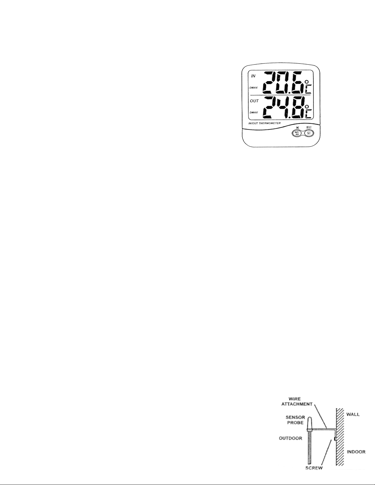
MOUNTING THE EXTERNAL SENSOR: Follow these steps to mount the external probe.
1. Drive a screw into the wall at the desired location, to fix the external sensor probe wire attachment
to the wall.
2. Route the external probe cable through a window.
 Loading...