

Page 1

Type K/J
Thermometers
800004 & 800007
Page 2

CONTENTS
INTRODUCTION .......................2
PANEL DESCRIPTION ..................3
MEASUREMENT PROCEDURES .......4-8
OFFSET ADJUSTENT ..................9
AUTO POWER OFF ...................10
BATTERY REPLACEMENT .............10
SPECIFICATIONS .....................11
OPTIONAL ACCESSORIES .............12
WARRANTY .........................12
INTRODUCTION
Mini sized and light weight, this unit provides
extremely accurate and reliable temperature
measurement with all the versatility and range
of type K & J thermometers. Features relative,
min/max/ave temperature, hold, auto power
off, and touch tone buttons. Model 800007
will read and display results from two probes
simultaneously and track the difference
between them (T1-T2). Comes with a 9V
battery and beaded wire probe (2 probes for
800007). CE rated.
2
Page 3
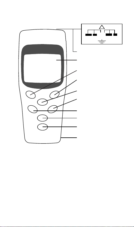
PANEL DESCRIPTION
!
24V
- +
MA X
- +
1. Probe Input (top of unit)
2. Display
3. °C/°F
4. Min/Max
5. Type K/J
6. REL (relative) / adj
7. HOLD / Auto Off
8. Power
9. T1-T2 (difference 800007 only)
10. Battery Compartment (back of unit)
3
1
2
3
4
5
6
7
8
9
10
Page 4

MEASUREMENT PROCEDURES
Measurement Mode
1. Press the POWER button.
2. Press the °C/°F button to select the
temperature scale. “°C” or “°F” will
appear on the LCD.
3. Press the TYPE button to select your sensor
type. “K” or “J” will appear on
the LCD.
4. To select sensor type for T2 (model 800007
only), press and hold the T1-T2 button and
T2 will appear on the primary display (the
upper half of the LCD). Press the TYPE
button to select “K”
or “J” sensors.
5. The thermometer will automatically
save your sensor choice when the meter is
turned off, and will return to the saved type
when the meter is turned back on.
6. Insert the probe plug(s) into the PROBE
INPUT socket. Be sure to match the plug’s
polarity to the input’s polarity
( - + ).
7. Temperature reading(s) will appear on the
LCD. For 800007, the T1 reading appears
on the primary display and T2 reading on the
lower display.
4
Page 5

MEASUREMENT PROCEDURES
Note…
To obtain the most accurate reading, the
probe plug must be the same temperature
as the socket.
Hold Mode
1. Press the HOLD button during
measurement to freeze the displayed
temperature. “HOLD” and the temperature
are shown.
2. Press the HOLD button again to exit
this mode.
Note...
When the Hold function is enabled, all
function keys are disabled except for the
POWER button.
Maximum/Minimum Mode
The thermometer must be in the Max/Min
Mode to display max, min or average values.
These values are not updated during
temperature readings taken in the standard
Measurement Mode.
Note…
The POWER, C/F, TYPE, REL and T1-T2
buttons will not operate in Max/Min Mode.
5
Page 6

MEASUREMENT PROCEDURES
1. The max value is updated only when
exceeded.
2. With the meter on, press the MAX/MIN
button once. “MAX” and the maximum
(peak) temperature appear on the LCD.
3. The min value is updated only when a
lower temperature is recorded.
4. Press the MAX/MIN button again.
“MIN” and the minimum temperature
appear on the LCD.
5. Press the MAX/MIN button again. “AVG” and
the average temperature appear on the LCD.
6. The max/min/ave temperatures are held in
memory until the meter is turned off.
7. To exit this mode, press and hold the
MAX/MIN button for at least 2 seconds.
The current temperature appears on the LCD.
Note…
The primary display shows current channel
readings of min/max/ave. The lower display
shows current channel readings of actual
temperature. For model 800007, to view
another channel reading of min/max/ave,
press and hold the T1-T2 button to switch
from T1 to T2 and vice versa.
6
Page 7

MEASUREMENT PROCEDURES
Relative Measurement
1. Press the REL button during measurement
to store the current temperature into memory.
“REL” and “0.0°” appear on the LCD.
2. As subsequent temperatures are
measured, the difference (higher/lower)
appear on the LCD.
3. Press the REL button again to exit.
EXAMPLE: A temperature reading of 75.0°F
was stored in memory by pressing the REL
button. Next, the probe was placed in a 55.0°F
environment. “REL” and “-20.0°F” appear on
the LCD.
Note…
The upper half of the LCD displays current
channel readings of REL. The lower half
displays current channel readings of actual
temperature. For model 800007, to view
another channel reading of REL, press and
hold the T1-T2 button to switch from T1 to T2
and vice versa.
7
Page 8

MEASUREMENT PROCEDURES
T1 °F
K
79.5
K
52.3
°F
T2
T1-T2
°F
K
27.2
K
52.3
°F
T1-T2 Δ Mode (800007 Only)
Using two probes, model 800007 will display
the Δ (difference) between the T1 and T2
temperatures. The MAX/MIN and REL buttons
will not operate in Δ Mode.
1. With the meter on, press the T1-T2
button once.
In the following example, the T1 value is 79.5°F,
the T2 value is 52.3°F, and the difference is
27.2°F. Or, T1 (79.5) - T2 (52.3) = 27.2°F.
2. Press T1-T2 to disable the Δ function.
Note…
The primary display shows T1-T2 temperature.
The lower display shows current channel
readings of actual temperature. To view another
channel reading of actual temperature on the
lower display, press and hold the T1-T2 button
to switch from T1 to T2 and vice versa.
8
Page 9

OFFSET ADJUSTMENTS
You can adjust the offset to compensate for
meter and probe error.
1. Press and hold REL to enter offset
setup mode.
2. Press TYPE or POWER to increase or
decrease the offset value, respectively.
The maximum adjustment is ±5°C or ±9°F.
3. Press MAX/MIN to save and leave
offset mode.
4. For 800007 only: To adjust the offset
on another channel, press T1-T2 and
repeat steps 2-3.
Note...
The thermometer will save the offset value when
the meter is turned off, and will default to the
saved value when the meter is turned back on.
9
Page 10

AUTO POWER OFF
1. The thermometer will automatically turn off
after 15 minutes of inactivity.
2. Press and hold the HOLD button to disable
or enable the auto power off function.
BATTERY REPLACEMENT
1. When the low battery icon is displayed,
turn off the meter and remove the probe(s).
2. Slide BATTERY COMPARTMENT cover
down to install a fresh 9V battery.
3. Replace the cover. Battery life is
approximately 200 hours.
10
Page 11

SPECIFICATIONS
Accuracy ±(0.05% of reading + 0.7°C
or 1.4°F) when inside the
range of 23± 5°C, < 80%RH
OR
0.01% of reading + 0.03°C
per each °C outside the
specied range of 23± 5°C
or 73± 9°F
Type K -200 ~ 1370°C
(-328 ~ 2498°F)
Type J -200 ~ 1050°C
(-328 ~ 1922°F)
Resolution 0.1
Weight 6 oz (170g)
Dimension 5¼ x 2 ¼ x 1¼”
130 (L) x 56 (W) x 38 (H) mm
Operating
Environment
Storage
Environment
Overload
Indicator
5°C to 40°C (41°F to 104°F),
RH <80%
10°C to 60°C (14°F to
140°F), RH <70%
“OL” indicates either over
range (positive temp.) or no
probe(s) attached.
“-OL” indicates below range
(negative temp.)
11
Page 12

OPTIONAL ACCESSORIES
800060~97 Type K / J Thermocouple Probes
840090 Water Resistant Instrument Pouch
850000 Rubber Boot
WARRANTY
Sper Scientic warrants this product against
defects in materials and workmanship for
ve (5) years from the date of purchase, and
agrees to repair or replace any defective unit
without charge. If your model has since been
discontinued, an equivalent Sper Scientic
product will be substituted if available. This
warranty does not cover damage resulting from
accident, misuse, or abuse of the product. To
obtain warranty service, ship the unit postage
prepaid to:
SPER SCIENTIFIC LTD
8281 E. Evans Rd., Suite #103
Scottsdale, AZ 85260
(480) 948-4448
Be sure to include a description of the problem
and your return address. Register your product
online at www.sperscientic.com, or return your
warranty card within 10 days.
09/09/13
12
 Loading...