


EASY FLASH MODULE 2.0
USER MANUAL
Speed Turtle Engineering LLC
Internet: www.speedturtleengineering.com
Customer Support: support@speedturtleengineering.com

Easy Flash Module 2.0 User Manual
IMPORTANT NOTES!
Before the installation and use of the Easy Flash Module 2.0 (EFM 2.0), thoroughly read and understand the module features and instructions contained in this manual!
The use of a flashing vehicle light system may be regulated by state, county, or municipal authorities. It is the responsibility of the end user to know and comply with these regulations.
The installation of the Easy Flash Module 2.0 (EFM 2.0) will modify the vehicle’s electronic communication system. This modification may affect the warranty of your vehicle. It is the responsibility of the end user to verify the warranty conditions with the vehicle manufacturer. Also, the use of the Easy Flash Module 2.0 (EFM 2.0) may shorten the life of the vehicle’s light bulbs, headlight assemblies, and electronic modules.
V1.3 |
Speed Turtle Engineering LLC |
Page | 1 |

Easy Flash Module 2.0 User Manual |
|
Contents |
|
IMPORTANT NOTES! ............................................................................................................................... |
1 |
Preface .................................................................................................................................................... |
3 |
General Operation .................................................................................................................................. |
3 |
Easy Flash Module 2.0 Overview............................................................................................................. |
4 |
Module Layout .................................................................................................................................... |
4 |
Switch Interface Harness..................................................................................................................... |
4 |
Supported Vehicles.................................................................................................................................. |
6 |
Installation .............................................................................................................................................. |
7 |
Module Modes ........................................................................................................................................ |
8 |
Module Operation:.................................................................................................................................. |
9 |
Switch Inputs....................................................................................................................................... |
9 |
Integrated Vehicle Switch ................................................................................................................... |
9 |
Active Modes.................................................................................................................................... |
11 |
Pattern Selection.............................................................................................................................. |
11 |
Individual Lamp Configuration......................................................................................................... |
12 |
Module Overrides............................................................................................................................. |
12 |
Updating Module Software.............................................................................................................. |
13 |
Troubleshooting ................................................................................................................................... |
13 |
Frequently Asked Questions................................................................................................................. |
14 |
Questions / Comments ?...................................................................................................................... |
15 |
V1.3 |
Speed Turtle Engineering LLC |
Page | 2 |

Easy Flash Module 2.0 User Manual
Preface
This manual describes the features and operation of the Easy Flash Module 2.0 (EFM 2.0) with software version V1.21. Speed Turtle Engineering recommends you always run the latest available EFM 2.0 software. The latest software is always available for download at SpeedTurtleEngineering.com. To check and update your module software version, use the STE Configuration Utility program. STE configuration Utility installation and use is described in detail in the STE Configuration Utility User Manual also available at SpeedTurtleEngineering.com.
General Operation
The Easy Flash Module 2.0 (EFM 2.0) provides a simple and effective way to flash the factory exterior lights of supported vehicles. The system is easily installed in minutes and is a true plug and play solution. If equipped and supported, the module will flash the following lights:
-Front Low Beams
-Front High Beams
-Front Turn Signals
-Front Fog Lamps
-Front LED Accents
-Rear Turn Signals
-Rear Stop Lamps
-Third / Center Mounted Brake Lamp
-Reverse Lamps
-Rear LED Accents
-Pickup Bed Lamp
Unlike other solutions, the EFM 2.0 does not require any cutting or reconfiguration of the vehicle’s wiring harness. This allows the module to be easily installed by anyone in minutes. The plug and play installation also allow the module to be removed and installed in another vehicle without repairing or replacing vehicle components.
V1.3 |
Speed Turtle Engineering LLC |
Page | 3 |
Easy Flash Module 2.0 User Manual
The module has two switch inputs as well as an existing vehicle button (most vehicles) that can be configured to activate the module either through a long press or quick cycle.
The EFM 2.0 has applications in a wide range of markets. They include, but are not limited to: police and fire, municipal vehicles, security personal, road workers, towing vehicles, or service vehicles.
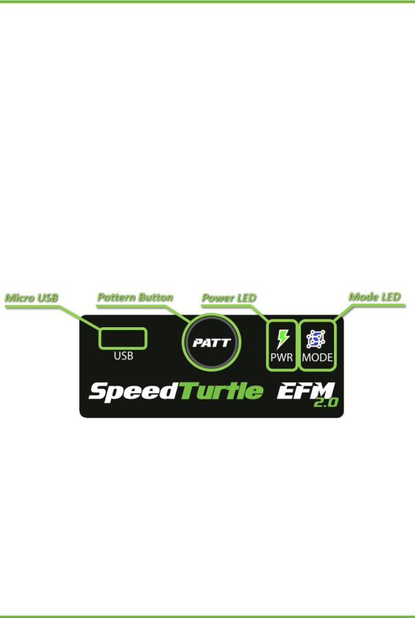
Easy Flash Module 2.0 Overview
Module Layout
The Easy Flash Module 2.0 features six main components: The OBD-II connector, switch interface connector, power and mode LEDs, pattern button and micro USB port. These components locations are outlined below.
Switch Interface Harness
The purpose of the switch interface harness is to provide an ON/OFF signal to the module. There are two switch interface harness options:
Toggle Switch Harness: This harness provides a simple ON/OFF toggle switch with adhesive backing. There are two internal LEDs to the toggle switch with green indicating the switch is OFF and orange indicating the switch is ON. While this is the simplest of the two harnesses
V1.3 |
Speed Turtle Engineering LLC |
Page | 4 |
 Loading...