

Page 1

EASY FLASH
MODULE USER’S
MANUAL
Speed Turtle Engineering LLC
Phone: (586) 738-0533
Internet: www.speedturtleengineering.com
Customer Support: support@speedturtleengineering.com
Page 2

IMPORTANT NOTES!
• The use of a flashing vehicle light system may be regulated by state, county, or municipal
authorities. It is the responsibility of the end user to know and comply with these
regulations.
• The installation of the easy flash module will modify the vehicle’s electronic
communication system. This modification may affect the warranty of your vehicle. It is the
responsibility of the end user to verify the warranty conditions with the vehicle
manufacturer. Also, the use of the easy flash module may shorten the life of the vehicle’s
light bulbs, headlight assemblies, and electronic modules.
• Before attempting the installation of the easy flash module, thoroughly read and
understand the module features and instructions contained in this manual!
V1.4 Speed Turtle Engineering LLC Page | 1
Page 3
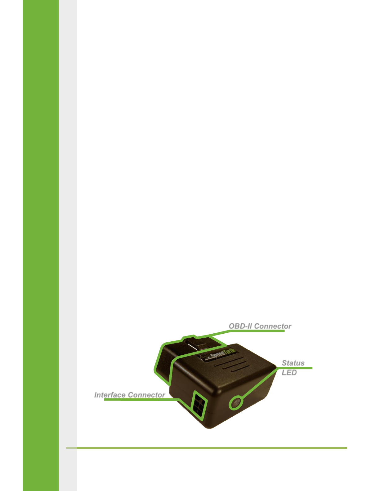
Basic Operation
Status
LED
OBD-II Connector
Interface Connector
The Easy Flash Module is a simple and effective way to flash the factory exterior lights of
supported vehicles. The system is easily installed in minutes and is a true plug and play solution for
most vehicles. If equipped, the module will flash the following lights: front low beams, front high
beams, front fog lights, front and rear turn indicator lamps, and side view mirror turn signal marker
lamps.
Unlike other solutions, the Easy Flash Module does not require any cutting or
reconfiguration of the vehicle’s wiring harness. This allows the module to easily be removed and
installed in another vehicle without repairing or replacing vehicle components.
The Easy Flash Module can be utilized by a wide range of markets. They include, but are not
limited to: police and firefighter vehicles (both volunteer and career), municipal vehicles, security
personal, road workers, towing vehicles, or utility vehicles.
Easy Flash Module Overview
Module Features
The Easy Flash Module features three main components: The OBD-II connector, the green
status LED, and the interface harness connector. These components are outlined below. More
information on the status LED can be found in the troubleshooting section.
V1.4 Speed Turtle Engineering LLC Page | 2
Page 4

Interface Harness
The purpose of the interface harness is to provide the on/off signal to the module as well as
provide a connection to the vehicles data network on select models. The on/off signal can be
provided via toggle switch or voltage input.
Currently there are four available interface harness options:
Dodge/Ram Truck with toggle switch
Dodge/Ram Truck with voltage input
Ford vehicle with toggle switch
Ford vehicle with voltage input
Some users may prefer the simplicity of the self-adhesive toggle switch harness while others may
wish to connect the on/off signal to a pre-existing switch (voltage input). The acceptable range for
the voltage input is 5-17 volts.
The Dodge/Ram interface harnesses differ from the Ford harnesses by the addition of two
vehicle network communication wires. Specific instructions on how to connect these wires can be
found in the installation section of this manual.
The interface harness plugs into the left side of the easy flash module using a small black
square connector. It is secured by a locking tab attached to the top of the harness connector. To
disconnect the interface harness, depress the connector’s locking tab and gently pull the connector,
NOT the wires!
V1.4 Speed Turtle Engineering LLC Page | 3
Page 5

Supported Vehicles
The following vehicles are currently supported by the Easy Flash Module.
Installation
Ford Vehicles
1) If using the switch input interface harness, mount the toggle switch using the self-adhesive
pad located on the bottom of the switch in a safe and easily accessible location. Route the
switch harness in a manner that does not interfere with normal vehicle operation. Secure
with zip ties. If using the voltage input interface harness, connect the white wire to a 5-14
volt fused switch source. Route the voltage input wire in a manner that does not interfere
with normal vehicle operation. Secure with zip ties.
2) Plug the small black square connector on the interface harness into the left side of the Easy
Flash module. Plug the Easy Flash Module into the OBD-II connector of the vehicle.
V1.4 Speed Turtle Engineering LLC Page | 4
Page 6

3) Test the module by activating the switch or voltage input. If the module does not work as
expected see the Troubleshooting section of this manual.
Chrysler Vehicles
2009 – 2012 Ram Truck
1) Remove the driver’s door weather stripping
by pulling towards the driver’s seat. (Figure
1)
2) Remove the driver’s side dash end panel by
pulling towards the driver’s door. The panel
is held in by a series of spring loaded clips.
(Figure 2)
3) After removing the dash end panel, a wiring
harness with one or two connectors will be visible (depending
on vehicle trim level). Disconnect the green 16 pin connector on the left. (Figure 3)
4) Two wires will need to be tapped using the supplied red t-tap connectors. These wires are
the two leftmost wires in the connector.
The first wire in connector pin 1 is white
with an orange stripe. The second wire in
pin 9 is white with a gray stripe. The pin
numbers are molded into the back of the
connector for reference.
5) Place one of the two wires from the
previous step into the ‘V’ channel of the red
t-tap connector. (Figure 4)
6) Fold the t-tap connector in half by hand.
Using a pair of pliers, firmly squeeze the t-
tap connector. This will lock the connector
from opening as well as seat the wire in the
tap. Repeat steps 4 and 5 for the remaining
wire. (Figure 5 & 6)
7) Reconnect green 16 pin connector.
V1.4 Speed Turtle Engineering LLC Page | 5
Page 7

8) Connect the orange wire of the Easy Flash Module interface harness
to the white wire with orange stripe by inserting the spade
connector into the side of the t-tap connector. Repeat the process
by connecting the black wire of the Easy Flash Module to the white
wire with gray stripe. (Figure 7)
9) Route the Easy Flash Module interface harness down to the OBD-II
connector located on the underside of the driver’s side dash. Secure
with zip ties. Ensure the interface harness is routed in a manner that
does not interfere with normal vehicle operation.
10) Reinstall driver’s side dash end panel and driver’s door weather stripping by pressing back
into position.
11) If using the switch input interface harness, mount the toggle switch using the self-adhesive
pad located on the bottom of the switch in a safe and easily accessible location. Route the
switch harness in a manner that does not interfere with normal vehicle operation. Secure
with zip ties. If using the voltage input interface harness, connect the white wire to a 5-14
volt fused switch source. Route the voltage input wire in a
manner that does not interfere with normal vehicle
operation. Secure with zip ties.
12) Plug the small black square connector on the interface
harness into the left side of the Easy Flash module. Plug the
Easy Flash Module into the OBD-II connector of the vehicle.
(OBD-II connector shown in Figure 8)
13) Test the module by activating the switch or voltage input. If the module does not work as
expected, see the Troubleshooting section of this manual.
2013 – 2015 Ram Truck and Durango
Follow Ford installation instructions.
V1.4 Speed Turtle Engineering LLC Page | 6
Page 8

Troubleshooting
Status LED
The green status LED indicates the current mode of the Easy Flash Module. Determining the
current module mode is the first step in troubleshooting any problem. There are a total of seven
modes. These modes are described in detail below.
Mode 1: Indicates the module is in the normal OFF state. In Mode 1, the status LED will blink
once followed by three seconds of non-illumination. The sequence will then repeat.
Mode 2: Indicates the module is in the first phase of the startup routine. In Mode 2, the
status LED will blink twice followed by three seconds of non-illumination. The sequence will
then repeat.
Mode 3: Indicates the module is in the second phase of the startup routine. In Mode 3, the
status LED will blink three times followed by three seconds of non-illumination. The
sequence will then repeat.
Mode 4: Indicates the current vehicle is not supported by the device. In Mode 4, the status
LED will blink four times followed by three seconds of non-illumination. The sequence will
then repeat.
V1.4 Speed Turtle Engineering LLC Page | 7
Page 9

Mode 5: Indicates the module is in standby mode. In Mode 5, the status LED will
progressively increase then decrease in intensity followed by six seconds of non-
illumination. The sequence will then repeat.
Mode 6: Indicates the module is in the normal ON state. In Mode 6, the status LED will blink
continuously.
Mode 7: Indicates the module is in diagnostic mode. In Mode 7, the status LED will remain
on constantly.
Once the current module mode has been established using the status LED and the mode
explanation above, the Troubleshooting Matrix chart below can be used to identify the appropriate
troubleshooting actions.
V1.4 Speed Turtle Engineering LLC Page | 8
Page 10

If problems persist after following the Troubleshooting Matrix, contact us as
support@SpeedTurtleEngineering.com or by visiting our website at SpeedTurtleEngineering.com.
Provide as many details as possible in addition to: vehicle make, vehicle model, vehicle model year,
module mode, current symptom and any troubleshooting steps you may have already taken.
Frequently Asked Questions
How does it work?
o Traditionally, flasher systems operated by physically cutting the power wires to
specific lights and splicing control electronics in-line. The Easy Flash Module takes a
different approach by simply commanding the vehicle to illuminate specific lights.
This approach is faster and easier to install, less intrusive to vehicle wiring, and more
cost effective.
Does the Easy Flash Module support my vehicle?
o The Easy Flash Module currently supports a wide range of vehicles. A list of
supported vehicles and model years, at the time of printing, can be found in the
Currently Supported Vehicles section of this manual. The most up to date list can be
found at SpeedTurtleEngineering.com .
Are there any tools required for installation?
o For most vehicles, there are no required tools. For Dodge / Ram Vehicles the use of
a standard pair of pliers is required.
Can the module be connected to my own switch or activation signal?
o Yes, the module can be connected to an existing switch or voltage source for
activation. Users that wish to provide their own input signal should order the Easy
Flash Module with the voltage input harness. The module will accept activation
signals in the range of 5 – 17 volts. Voltages higher than 17 volts can permanently
damage the module.
What does the blinking green status light mean?
o The green status light communicates the current mode of the module. This mode is
used for troubleshooting and is explained in more detail in the Troubleshooting
section.
V1.4 Speed Turtle Engineering LLC Page | 9
Page 11

Will the module work in more than one vehicle?
o Yes, the Easy Flash module will work in any supported vehicle. There are no
restrictions on how many vehicles you can use the module on. If the module is
planned to be used on more than one vehicle, purchasing a separate vehicle
interface harness for each vehicle may be convenient.
My vehicle is not on the supported list. Are there any plans to support it?
o At Speed Turtle we are continuously working to provide you with more supported
vehicles and model years. With that said, there are some vehicle lines that cannot
be supported due to the technical aspects of how the vehicle operates. This is
currently true for all GM vehicles. If there is a specific vehicle that you would like to
request, we would love to hear from you at support@SpeedTurtleEngineering.com.
Occasionally, I hear the turn signal indicator click or see the dash back lights flicker. Is this
normal?
o Yes, this is normal and is not detrimental in any way. Turning the vehicle’s headlight
switch to the park or ON position while the module is active will mitigate the
occasional flicker of the dash back lights.
I already have a device plugged into the OBD-II connector. Can I still use the Easy Flash
Module?
o Dodge / Ram vehicles are not compatible with concurrent OBD-II devices. Other
vehicles may be compatible with concurrent OBD-II devices by using a Y-cable.
Questions / Comments ?
Whether you have questions, comments, or general feedback, we would love to hear from
you at SpeedTurtleEngineering.com.
V1.4 Speed Turtle Engineering LLC Page | 10
 Loading...