


User Guide
802.11ac Wave 2 Router
Model Number RAC2V1K
Table of Contents |
|
|
2 |
1 Hardware Setup |
|
......................................................................................................................... |
2 |
1.1 Getting To Know Your WiFi Router....................................................................................................... |
2 |
1.2 Unpack WiFi Router’s box..................................................................................................................... |
3 |
1.3 Hardware Features.................................................................................................................................... |
4 |
1.3.1 Front Panel....................................................................................................................................... |
4 |
1.3.2 Rear Panel....................................................................................................................................... |
5 |
1.4 Position Your WiFi Router...................................................................................................................... |
6 |
|
7 |
2 Login to your WiFi Router Web GUI................................................................. |
7 |
2.1 Login.............................................................................................................................................................. |
7 |
2.2 Wizard Setup............................................................................................................................................. |
10 |
2.3 Basic Setup................................................................................................................................................ |
13 |
2.3.1 Router............................................................................................................................................... |
13 |
2.3.2 WPS Setup....................................................................................................................... |
15 |
2.3.3 LAN Setup.................................................................................................................................... |
17 |
2.3.4 WAN Setup.................................................................................................................................... |
18 |
2.3.5 Parental Control......................................................................................................................... |
23 |
2.3.6 Services......................................................................................................................................... |
25 |
2.3.7 System........................................................................................................................................... |
35 |
2.4 Advanced Setup..................................................................................................................................... |
36 |
2.4.1 Network......................................................................................................................................... |
36 |
2.4.2 Services Config.......................................................................................................................... |
66 |
2.4.3 Security......................................................................................................................................... |
79 |
2.4.4 QoS................................................................................................................................................ |
92 |
2.4.5 Admin.......................................................................................................................................... |
100 |
2.4.6 Tools............................................................................................................................................. |
104 |
2.4.7 Status.................................................................................................................................................... |
106 |
|
113 |
3 FCC Statement |
|
........................................................................................................................ |
113 |
1 Hardware Setup
1.1 Getting To Know Your WiFi Router
This product is designed for the In-Home and Business WiFi service for Spectrum customers. With a custom industrial design, this WiFi Router can be placed in a central location to deliver superior WiFi network coverage.
WiFi Router provides:
1.High performance:
·Dual-Core ARM up to 1.7G/1GB DDR RAM.
·Dual-Band wireless up to AC2350 (2.4G 150M * 4 + 5G 433M * 4).
·Gigabyte 1 x WAN/ 4x LAN Ethernet ports.
2. |
High security: |
Firewall/VPN supported. |
3. |
Easy to setup: |
Friendly wizard, visual setup & maintenance (Basic Mode), complete |
|
|
functions (Advanced Mode). |
4.USB-based services: File/media/printer sharing.
The WiFi Router is an ideal choice for residential and SMB (Small Business) users who can enjoy a variety of wireless applications and services.
This chapter contains the following contents:
·Unpack Your WiFi Router
·Hardware Features
·Position Your WiFi Router
2 |
Model Number RAC2V1K |

1.2 Unpack WiFi Router’s box
Open the box and remove the WiFi Router, power adapter, Quick Start Guide, WiFi Network Name and Password Sticker and Ethernet cable.
WiFi Router |
Power Adapter |
Figure 1. Check the package contents
The box contains the following items:
·WiFi Router.
·AC power adapter.
·Quick Start Guide.
·WiFi Network Name and Password Sticker.
·Ethernet cable
If any items are missing or damaged, please contact your Charter Communications. Please keep original packing materials in case you need to return the product for repairing.
1.3 Hardware Features
Before setup please take a moment to become familiar with the Front Panel and Rear Panel of your WiFi Router. Pay particular attention to the LED on the front panel. You should know the surface structure of your WiFi Router only.
1.3.1 Front Panel
The WiFi Router front and back panels feature the status LED and buttons as shown in the following figure
Figure 2. WiFi Router front view
Front panel LED status · Off:
· Blue Flashing (0.4 second intervals): · Blue Pulsing 1 second intervals:
· Blue solid:
· Red Flashing:
· Red and Blue alternate Pulsing:
· Red solid:
·LED on front of device will dim to low (65%) when there is no settings activity or connectivity issues for 120 hours.
·If any settings are changed or connectivity issues occur LEDs will return to normal (100%) brightness.
3 |
Model Number RAC2V1K |
4 |
Model Number RAC2V1K |

1.3.2 Rear Panel
There are Ethernet and USB connections and buttons shown in the following figure.
1.4 Position Your WiFi Router
The WiFi Router lets you access your network from virtually anywhere within the operating range of your wireless network. However, the wireless communicating distance varies significantly due to placement of the WiFi Router. For example, the thickness and number of walls the wireless signal passes through can limit the range. For best results, WiFi Router is likely to be place like this:
·Near the center of the area where your computers and other devices operate, and preferably within line of sight to your wireless devices.
·So it is accessible to an AC power outlet and near Ethernet cables for wired computers.
·In an elevated location such as a shelf, keeping the number of walls and ceilings between the WiFi Router and your other devices to a minimum.
·Away from electrical devices that are potential sources of interference. Equipment
that might cause interference includes ceiling fans, home security systems, microwaves, computers, the base of a cordless phone, or a 2.4 GHz cordless phone.
·Away from any large metal surfaces, such as a solid metal door or aluminum studs. Large expanses of other materials such as glass, insulated walls, fish tanks, mirrors, brick and concrete can also affect your wireless signal.
Figure 3. WiFi Router rear panel
·Factory Reset (pinhole): Press the pinhole and hold over 5 seconds, the WiFi Router will
|
|
reset to factory. |
· |
WPS Button: |
Push the button more than 1 second to activate WPS. Reference |
|
|
2.3.2 WPS Setup. |
· |
Ethernet (LAN) Port: |
Connect Ethernet cables for LAN (local area network) |
|
|
connections, e.g. network switch, hub, personal computer or |
|
|
Internet devices. |
· |
Internet (WAN) Port: |
Connect Ethernet cable for WAN (Wide Area Network) |
|
|
connection to modem. This connects the Ethernet and other |
|
|
access lines e.g. modem. |
· |
USB (3.0) Port: |
Connect a USB Printer, U-Disk or USB drive. For printer and |
|
|
folder sharing, reference 2.3.6 Services. |
· |
Power: |
Use the bundled AC adapter to connect your WiFi Router to a |
|
|
power source. |
5 |
Model Number RAC2V1K |
6 |
Model Number RAC2V1K |

2 Sign-In Your WiFi Router Web GUI
The WiFi Router contains an intuitive graphical user interface (GUI) based on web, which lets administrator easily configure its features through a web browser.
2.1 Sign-In
1.Open a web browser, then key in the WiFi Router’s default IP address: http://192.168.1.1, and click Enter key in the keyboard;;
2.On the sign in webpage, type in its Username and password: admin (admin), then click Login button.
After the administrator has logged into the WiFi Router, some basic information about it will be displayed in the browser.
On the right top side, there are two command buttons: Change Password and Logout. Please click the Logout button when administrator intends to leave the Web GUI.
When the Change Password button has been clicked, the browser will navigate to the corresponding webpage.
7 |
Model Number RAC2V1K |
8 |
Model Number RAC2V1K |

On this page, user should just type in new password in New Password and Retype New Password, then click Apply button. Web GUI user sign in password will be changed.
2.2 Wizard Setup
The wizard can navigate the administrator to configure basic settings for the WiFi Router, which makes the set up of the WiFi Router much easier.
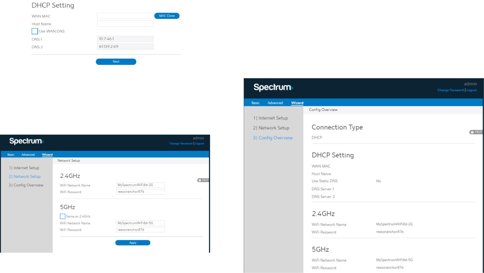
Internet Setup
After the administrator has clicked the Wizard button, the Internet Setup page will be displayed.
Connection Type:
There are 5 kinds of connection types: DHCP, PPPoE, Static, PPTP and L2TP.
1. DHCP: Enable WiFi Router to obtain IP addresses automatically. This setting is the default for Spectrum services. More types of settings, refer to 2.3.4 WAN Setup.
9 |
Model Number RAC2V1K |
10 |
Model Number RAC2V1K |
2. WiFi Password: A password used by WiFi Router to authenticate wireless connections. These are defaulted from the printed WiFi password on the back of the WiFi Router. You can change it here, but they would no longer match the sticker on your router.
3. When done, click Apply.
Config Overview
After click the Apply icon, administrator comes to Config Overview page, which displays a summary of configuration information. If the settings are all correct, administrator should click Apply icon.
·WAN MAC:
·Host Name:
·DNS 1 & DNS 2:
·Click Next.
MAC address of WAN port.
This field allows lets administrator provide a name for WiFi Router. Either of them indicates the IP address of a DNS Server.
Network Setup
After you have clicked Next icon in Internet Setup page, you can come here or you will refer to the below picture.
1. WiFi Network Name:
Name for a wireless network, that’s to say it’s used to identify the wireless network. WiFi devices automatically detect all networks within its communication range. These are defaulted from the printed WiFi network name on the back of the WiFi Router. You can change them here, but they would no longer match the sticker on your WiFi Router.
11 |
Model Number RAC2V1K |
12 |
Model Number RAC2V1K |
2.3 Basic Setup
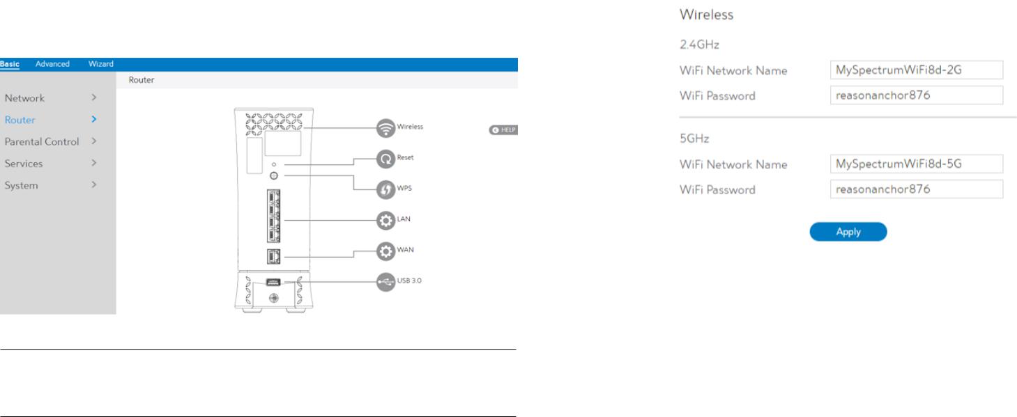
2.3.1 Router
From the navigation panel, go to Basic > Router.
NOTE: Click Reset Icon in the Web GUI is used to restart the WiFi Router. The WiFi Router hardware Factory Reset (pinhole) was pressed and hold over 5 seconds, it will reset to factory.
Wireless: |
This module is implemented to configure some basic settings for |
|
WiFi Router’s wireless connection. |
1. WiFi Network Name: A unique name that identifies the wireless network. Wireless device can automatically detect all networks within its communication range. The maximum length of a network name (SSID) is 32 characters.
A string used for connection authentication. Its length ranges from 8 to 63 characters (letters, numbers or a combination) or from 8 to 64 hex digits.
13 |
Model Number RAC2V1K |
14 |
Model Number RAC2V1K |

2.3.2 WPS Setup
WPS (WiFi Protected Setup) is a wireless security standard that lets the device easily connect a WiFi network. You can trigger the WPS function via the PIN code or WPS button.
Steps to enable WPS (WiFi Protected Setup):
1. From the navigation panel, go to Basic > Router.
2. |
Frequency: |
Selecting operating band (2.4 GHz or 5 GHz) for WPS function. Each |
|
|
one is enabled separately. |
3. |
Enable WPS: |
Selecting [On] to run WPS, which simplifies the process of connecting |
|
|
any device to the WiFi network. |
NOTE: Authentication method supported by WPS is: WPA2-Personal. Not supported methods are: Shared Key, WPA-Enterprise, WPA2-Enterprise and RADIUS.
8.PIN Code: The WPS PIN code which clients use to connect with the WiFi Router.
9.In the WPS Method field, select Push Button or Client PIN code. If you select Push Button, go to step 10. If you select Client PIN code, go to step 11.
10.Using with WPS button please following these steps:
a)Click Start or press the WPS button located on at the rear of the WiFi Router.
b)Press the WPS button on your wireless device. This is normally identified by the WPS logo.
11.To set up WPS using the Client’s PIN code, follow these steps:
a)Locate the WPS PIN code in wireless device’s in Web GUI.
b)Key in the Client PIN code on the text box.
12.Click Start.
15 |
Model Number RAC2V1K |
16 |
Model Number RAC2V1K |

2.3.3 LAN Setup
This module makes it easier for administrator to modify the default LAN IP Address.
Steps to modify LAN IP settings:
1. From the navigation panel, go to Basic > Router.
2. LAN IP: |
The LAN IP address of the WiFi Router. Its default value is 192.168.1.1. In |
|
IP-based networks, packets are sent to the network devices' specific IP |
|
addresses. |
3.Subnet Mask: Subnet mask of WiFi Router. Its default value is 255.255.255.0
4.DHCP Server: DHCP (Dynamic Host Configuration Protocol) is mostly used to allocate
IP address for LAN-side devices. And a DHCP server can inform LAN-side devices of DNS server’s address, default gateway IP and etc. This WiFi Router can allocate 253 IP addresses at most.
NOTE: It’s recommended for administrator to select DHCP Server for LAN IP setting. If not, administrator has to assign IP address to LAN-side device manually.
5. Click Apply.
2.3.4 WAN Setup
Click WAN button to configure the WAN connection settings:
1. Connection Type: Choose the Internet Service type. There are five options are DHCP, PPPoE, Static, PPTP and L2TP. Consult your ISP if you are unsure what kind of WAN connection types to select.
2. If you select DHCP, below show the steps to set
· WAN MAC: MAC (Media Access Control) address is a unique identifier that identifies your computer or device in the network. ISPs monitor the MAC addresses of devices that connect to their services, and would disallow Internet connection for new MAC addresses.
To fix this issue, you can do either of the following:
·Contact your ISP and request to update the MAC address associated with your ISP subscription.
·Clone or change the MAC address of the new device to match the MAC address of the
original device.
· Host Name: This field lets you provide a host name for WiFi Router. Usually it’s provided by ISP.
·DNS 1 & DNS 2: Either of them indicates IP address of a DNS server.
·Click Apply.
17 |
Model Number RAC2V1K |
18 |
Model Number RAC2V1K |
3. If you select PPPoE, below show the steps to set
·Username: This field is only available when you set the WAN Connection Type as PPPoE, PPTP or L2TP.
·Password: This field is only available when you set WAN Connection Type as PPPoE, PPTP or L2TP.
·DNS1 & DNS2: Either of them indicates IP address of a DNS server that WiFi Router will contact.
·Click Apply.
NOTE: All of the parameters mentioned above are provided. If you need assistance, please contact Charter customer service.
4. If you select Static, below show the steps to set
• |
IP: |
If WAN connection requires a static IP address, key in the IP address in |
|
|
this field. |
• |
Subnet Mask: |
If WAN connection requires a static IP address, key in the subnet mask in |
|
|
this field. |
• |
Gateway: |
If WAN connection requires a static IP address, key in the gateway IP |
|
|
address in this field. |
• DNS 1 & DNS 2: Either of them indicates IP address of a DNS server. |
||
• |
WAN MAC: |
MAC (Media Access Control) address is a unique identifier that identifies |
|
|
your computer or device in the network. ISPs monitor the MAC addresses |
|
|
of devices that connect to their services, and would disallow Internet |
|
|
connection for new MAC addresses. |
To fix this issue, you can do either of the following:
·Contact your ISP and request to update the MAC address associated with your ISP subscription.
·Clone or change the MAC address of the new device to match the MAC address of the original device.
•Click Apply.
19 |
Model Number RAC2V1K |
20 |
Model Number RAC2V1K |
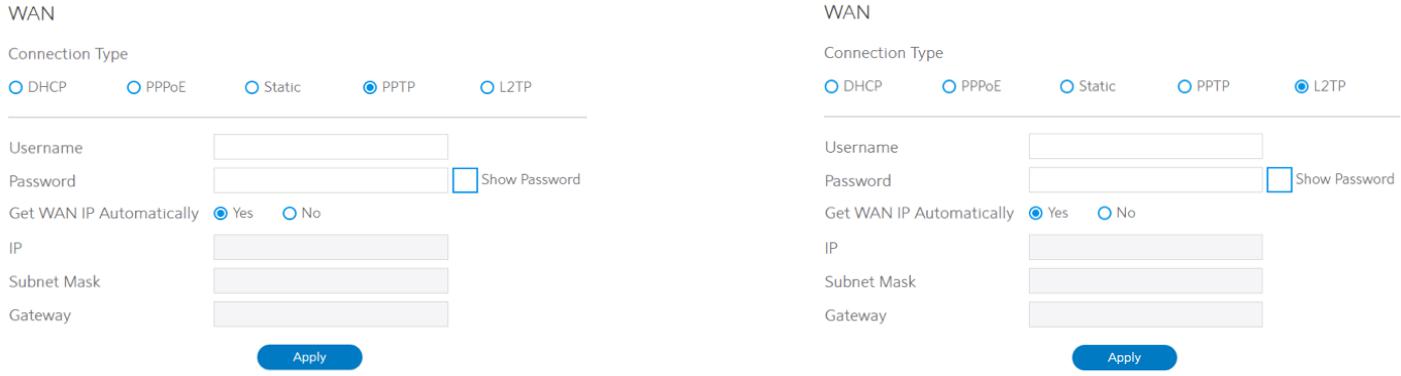
5. If you select PPTP, below show the steps to set |
6. If you select L2TP, below show the steps to set |
• |
Username: |
This field is only available when you set the WAN Connection |
Please refer to PPTP above for relevant settings descriptions and enter the required |
|
|
Type as PPPoE, PPTP or L2TP. |
information. |
• |
Password: |
This field is only available when you set WAN Connection |
|
|
|
Type as PPPoE, PPTP or L2TP. |
|
• Get WAN IP Automatically: Select Yes to get WAN IP automatically and No to enter IP |
|
||
|
|
manually below. |
|
• |
IP: |
If WAN connection requires a static IP address, key in the IP |
|
|
|
address in this field. |
|
• |
Subnet Mask: |
If WAN connection requires a static IP address, key in the |
|
|
|
subnet mask in this field. |
|
• |
Gateway: |
If WAN connection requires a static IP address, key in the |
|
|
|
gateway IP address in this field. |
|
• |
Click Apply. |
|
|
21 |
Model Number RAC2V1K |
22 |
Model Number RAC2V1K |
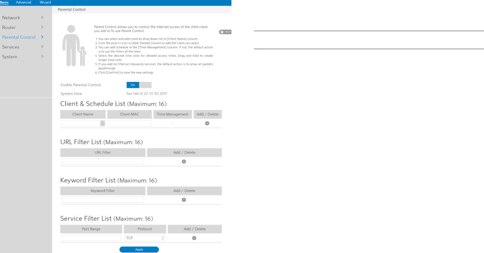
2.3.5 Parental Control
Parental Control lets administrator control the Internet access of the client.
Steps to set parental control function:
1.From the navigation panel, go to Basic > Parental Control.
2.Enable Parental Control: Select On to enable parental control, Select Off to disable
parental control.
3.Client & Schedule List:
•Client Name: Select client from the list. The name in the list stands for the client that is communicating with the WiFi Router.
•Client MAC: MAC address of the selected client.
NOTE: Client Name just makes it easier for technician to distinguish LAN-side devices. The Client MAC in fact specify the device with the Client Name.
•Time Management: Click , then setup the client’s schedule timetable to allow or deny client’s access to Internet.
•Add/Delete: Click  or
or to add/delete the profile.
4.URL Filter List
•URL Filter List: WiFi Router prevents LAN-side device from accessing the URL in list. •URL Filter: WEB URLs which contain the URLs defined by user.
For example, the filter "abc" can filter both "www.abc.com" •Add/Delete: Click  or
or to add/delete the profile.
5.Keyword Filter List
•Keyword Filter List: WiFi Router prevents LAN-side device from accessing to webpages contain the keyword in list.
•Keyword Filter: WEB URLs which contain the keywords defined by user. For example, the filter "abc" can filter both "www.abc.com"
•Add/Delete: Click  or
or to add/delete the profile.
6.Service Filter List
•Service Filter List: WiFi Router prevents LAN-side device from communicating with remote device with user defined Port Range and Protocol.
•Port Range: Defines the range of port in LAN side. The Port Range can be a single port like "xxxx", or a port range like "xxxx:xxxx".
•Protocol: Select the type of protocol that the Service Filter will use. •Add/Delete: Click  or
or to add/delete the profile.
7.Click Apply.
23 |
Model Number RAC2V1K |
24 |
Model Number RAC2V1K |

2.3.6 Services
2.3.6.1 USB Printer Sharing
USB Printer sharing lets administrator plug a USB printer to WiFi Router’s USB port and set up the printer server.
Steps to set up USB Printer sharing:
1.From the navigation panel, go to Basic > Service > USB Printer sharing.
2.Plug in the USB interface of the printer to the WiFi Router. Confirm your printer has been detected and click Continue.
3.Select one of the following modes to install the printer driver, and click Add printer.
·Auto select: Automatically searches for the appropriate printer driver and installs. If there is no corresponding printer driver, the system displays add a printer error; please select the correct printer driver manually.
·Select printer driver: Manually select the corresponding Printer brand and model.
·Choose PPD File: If the above methods are unable to correctly install the printer driver, then you can upload a PPD File. Select your PPD file and click the upload button.
4.Printer tab displays whether your printer is operating correctly with the print server, as below.
5.To check whether your printer is working correctly or not, input the LAN address (192.168.1.1) for the printer in Windows Finder.
6.Double-click the printer icon and if you see the status interface as shown below, the installation was successful. If an error message prompts that the driver cannot be found, then return to Add Printer settings and select the correct driver.
25 |
Model Number RAC2V1K |
26 |
Model Number RAC2V1K |

7. You can view print status information in the Print Jobs tab.
· Active: |
All active jobs, including processing and pending jobs. |
·Processing: The job currently processing/communicating print data.
·All Jobs: All print jobs.
2.3.6.2 FTP
FTP Server enables an FTP server to share files from USB disk to other devices via your local area network or via the Internet. This page shows information about the FTP Server and enable or disable it. If you want to set more configurations, please go to Advanced > Servers > FTP.
Display information on FTP Server:
1.From the navigation panel, go to go to Basic > Services > FTP.
2.Connect an external USB hard disk drive or USB flash drive to your WiFi Router, and your
device will be displayed here. |
|
3. Enable FTP: |
Click On/Off to enable/disable Internet access to FTP |
|
service. |
4. |
Maximum number of Connections: The maximum number of concurrent connections for |
|
|
|
the Network Neighborhood or FTP Server. |
5. |
Enable Outside Access: |
Select On/Off to enable/disable access to FTP server |
|
|
by wide area network. |
6. |
Outside Access: |
The numbers of external service ports |
|
|
(default value: 8021). |
7. Safely Remove Disk: |
Click to safely remove USB devices. When the USB |
|
|
|
disk is ejected successfully, the USB status shows 'No |
|
|
device '. |
27 |
Model Number RAC2V1K |
28 |
Model Number RAC2V1K |

2.3.6.3 Samba |
2.3.6.4 WebDAV |
Samba Share lets you set up the accounts and permissions for the Samba service. This page |
The client can write operations in WebDAV directory with appropriate permissions. This page |
shows information about the Samba Server and enable or disable it. If you want to set more |
shows information about the WebDAV Server and enable or disable it. If you want to set |
configurations, please go to Advanced > Servers > Samba. |
more configurations, please go to Advanced > Servers > WebDAV. |
·From the navigation panel, go to Basic > Services > Samba.
·Connect an external USB hard disk drive or USB flash drive to your WiFi Router, and your
|
device will be displayed here. |
|
· |
Enable Share: |
Click the On/Off to enable/disable Internet access to Samba service. |
· |
Device Name: |
Enter a name for your device and you can use this name in your web |
|
|
browser's URL field to quickly access the device as a Network Place |
|
|
service. |
· |
Work Group: |
Group name of the WiFi Router in Network Neighborhood. |
· Safely Remove Disk: Click to safely remove the disk. When the USB disk is ejected successfully, the USB status shows 'No device '.
1. From the navigation panel, go to Basic > Services > WebDAV.
2. |
Connect an external USB hard disk drive or USB flash drive to your WiFi Router, and your |
|
|
device will be displayed here. |
|
3. |
HTTP Access Port: |
The port to access the WebDAV server for HTTP protocol in the |
|
|
local area network (default value: 80). |
4. HTTPS Access Port: |
The port to access the WebDAV server for HTTPS protocol in the |
|
|
|
local area network (default value: 443). |
5. |
Enable Outside Access: Select On/Off to enable/disable access to WebDAV server by wide |
|
|
|
area network. |
29 |
Model Number RAC2V1K |
30 |
Model Number RAC2V1K |

6. Outside Access HTTP: The port number of external service ports via HTTP (default value: 8080).
7. Outside Access HTTPS: The port number of external service ports via HTTPS (default value: 8443).
8. Safely Remove Disk: Click to safely remove the disk. When the USB disk is ejected successfully, the USB status shows 'No device '.
2.3.6.5 DLNA
DLNA (Digital Living Network Alliance) lets you share audio, image and video. Your WiFi Router lets DLNA-supported devices access multimedia files from the USB disk connected to your WiFi Router. This page shows information about the DLNA Server and enable or disable it. If you want to set more configurations, please go to Advanced > Servers > DLNA.
Steps to set DLNA:
1. From the navigation panel, go to Basic > Services > DLNA.
2. |
Connect an external USB hard disk drive or USB flash drive to your WiFi Router, and your |
|
|
device will be displayed here. |
|
3. |
Enable DLNA Media Server: Switch DLNA media server on or off. |
|
4. Media Server Name: |
The DLNA server's name, which will be displayed by the |
|
5. |
Safely Remove Disk: |
media player such as VLC or Windows Media Player. |
Click to safely remove the disk. When the USB disk is ejected |
||
|
|
successfully, the USB status shows 'No device '. |
31 |
Model Number RAC2V1K |
32 |
Model Number RAC2V1K |
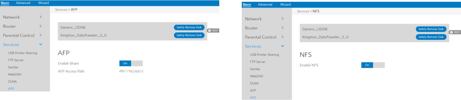
2.3.6.6 AFP
An AFP server is a kind of network file sharing server based on AFP protocol implementation, mainly used for file sharing between Linux and MAC systems. This page shows information about the AFP server and enable or disable it. If you want to set more configurations, please go to Advanced > Servers > AFP.
Steps to set AFP:
1.From the navigation panel, go to Basic > Services > AFP.
2.Connect an external USB hard disk drive or USB flash drive to your WiFi Router, and your
device will be displayed here.
3. Enable Share: Click On/Off to enable/disable AFP service.
4. Safely Remove Disk: Click to safely remove the disk. When the USB disk is ejected successfully, the USB status shows 'No device '.
2.3.6.7 NFS
Network File System Server is used to share the USB disk with clients via network. Clients can mount the remote disk to a local directory for a faster speed than using a Samba server. This page shows information about the NFS Server and enable or disable it. If you want to set more configurations, please go to Advanced > Servers > NFS.
Steps to set NFS:
1.From the navigation panel, go to Basic > Services > NFS.
2.Connect an external USB hard disk drive or USB flash drive to the WiFi Router, then device’s name will be displayed here.
3. Enable NFS:
4. Safely Remove Disk:
33 |
Model Number RAC2V1K |
34 |
Model Number RAC2V1K |
 Loading...