

Page 1
Quick Start Guide
00925-0200-9975, Rev AA
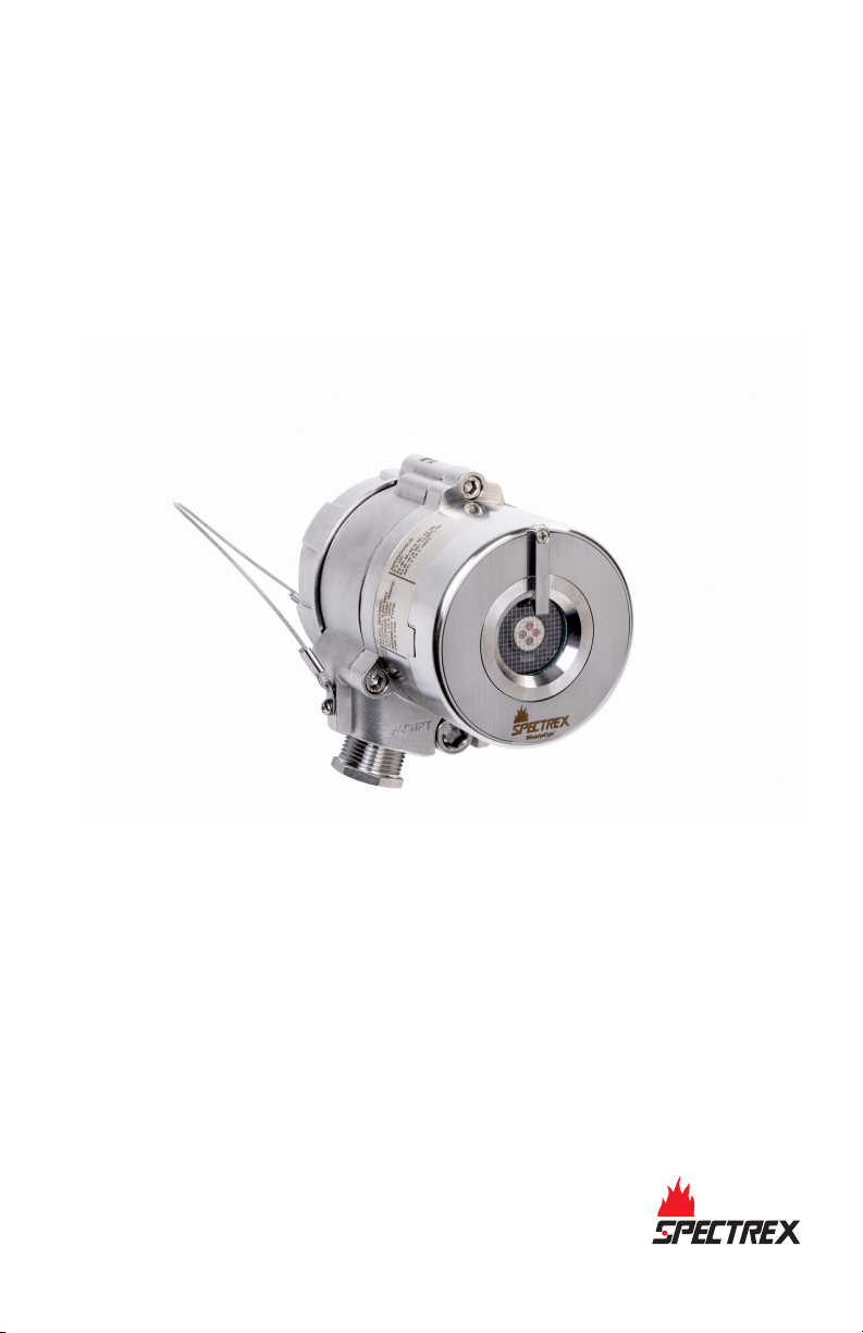
Spectrex SharpEye™ 40/40 Series
Flame Detectors
May 2021
Page 2

Quick Start Guide May 2021
Warning
WARNING
Physical access
Unauthorized personnel may potentially cause significant damage to and/or misconfiguration of end
users’ equipment. This could be intentional or unintentional and needs to be protected against.
Physical security is an important part of any security program and fundamental to protecting your
system. Restrict physical access by unauthorized personnel to protect end users’ assets. This is true for
all systems used within the facility.
Contents
Models......................................................................................................................................... 3
Installing the detector.................................................................................................................. 6
Special conditions for safe use....................................................................................................15
Declarations of Conformity........................................................................................................ 16
Reference data........................................................................................................................... 18
2 Spectrex.net
Page 3

May 2021 Quick Start Guide
1 Models
The SharpEye 40/40 Flame Detectors are electro-optical devices designed to
identify fire events, enabling alarm activation. The detectors are intended
for indoor or outdoor use and can be used stand alone or connected to an
alarm/automatic extinguishing system.
The SharpEye 40/40 series comprises the following detectors:
SharpEye 40/40-I
The SharpEye 40/40C-I, a multispectrum Quad-sense™ flame detector,
detects hydrocarbon fuel and gas fires with enhanced performance,
advanced long distance detection of hydrocarbon fires, fast detection in
under five seconds, and strengthened reliability. The SharpEye 40/40C-I is
based on proven triple infrared (IR3) technology, ensuring high sensitivity
with superior immunity to false alarms.
SharpEye 40/40C-M
The SharpEye 40/40C-M multispectrum Quad-sense IR flame detector is
specifically designed for the detection of hydrocarbon and hydrogen flames
with enhanced performance, advanced long distance detection of hydrogen
and hydrocarbon fires, fast detection in under five seconds, and
strengthened reliability. The SharpEye 40/40C-M is based on proven triple IR
(IR3) technology, ensuring high sensitivity with superior immunity to false
alarms.
SharpEye 40/40C-LB
The SharpEye 40/40C-LB is a dual spectrum ultraviolet (UV)/IR flame
detector, designed to provide fast detection in under five seconds of a range
of fires, such as hydrocarbon-based fuel and gas, hyrdoxyl, hydrogen, metal,
and inorganic.
SharpEye 40/40C-L4B
The SharpEye 40/40C-L4B is a dual spectrum UV/IR flame detector designed
to provide fast detection in under five seconds of hydrocarbon-based fuel
and gas fires.
SharpEye 40/40D-I
The SharpEye 40/40D-I, an ultra-fast multispectrum Quad-sense IR3 flame
detector, provides superior, longest distance detection of hydrocarbon fires
at up to 295 ft. (90 m), exceptional ultra-fast detection in under 50 msec,
and unparalleled reliability. The SharpEye 40/40D-I is based on proven Triple
IR (IR3) technology, ensuring highest sensitivity with best immunity to false
alarms.
Quick Start Guide 3
Page 4

Quick Start Guide May 2021
SharpEye 40/40D-M
The SharpEye 40/40D-M is a multispectrum Quad-sense IR flame detector
that provides superior, longest distance detection of hydrogen (at up to 165
ft. [50 m]) and hydrocarbon fires (at up to 295 ft. [90 m]), exceptional ultrafast detection in under 50 msec, and unparalleled reliability. The SharpEye
40/40D-M is designed to deal with the challenges of invisible fires based on
proven IR3 technology, ensuring highest sensitivity with best immunity to
false alarms.
SharpEye 40/40D-LB
The SharpEye 40/40D-LB is an ultra-fast UV/IR flame detector, which is able
to detect in under 20 msec and features a unique dual sensor with selectable
UV and IR channels that can be used separately or combined. The detector is
designed to detect a range of fires, such as hydrocarbon-based fuel and gas,
hydroxyl, hydrogen, metal, and inorganic.
SharpEye 40/40D-L4B
The SharpEye 40/40D-L4B is an ultra-fast UV/IR flame detector that is able to
detect in under 20 msec, and features a unique dual sensor with selectable
UV and IR channels that can be used separately or combined. The detector is
designed to detect hydrocarbon-based fuel and gas fires.
Table 1-1: SharpEye 40/40 Series General Technical Specifications
Spectral response Infrared and ultraviolet bands
Response time Varies according to model, typically under
Field of view Varies according to model, up to 100 degrees
Output 4-20 mA, relays, communication
Enclosure Stainless steel 316 or aluminum polyurethane
Operating voltage 18-32 Vdc
Maximum power rating 9.6 W
Relay contacts 2A/30 Vdc
Over voltage category 2
Relative humidity Non-condensing relative humidity up to 100%
5 seconds
painted
4 Spectrex.net
Page 5

May 2021 Quick Start Guide
CAUTION
If the product is used outside of specified limits, this voids the product
certification, and our company is not responsible for any incurred warranty
expense.
Do not open this product, except for the terminal compartment as listed in
this document, under any circumstances.
The detector is not field-repairable. Any attempt to modify or repair the
internal circuits or change their settings, as this will impair the system’s
performance and void the product warranty.
Opening the attachment screws to dismantle the front part of the detector
from remaining parts is restricted and voids the product warranty.
Quick Start Guide 5
Page 6

Quick Start Guide May 2021
2 Installing the detector
Table 2-1: Required Tools
Tool Function
Hex key 1.5 mm Fasten back cover security screw
Hex key 6 mm Adjust the tilt mount
Hex key 10 mm Affix the detector to the tilt mount
Hex key 3/16-in. Attach protective cover to detector
Flat screwdriver 6 mm Connect ground terminal
Flat screwdriver 2.5 mm Connect wires to the terminal blocks
Hex key 5/16-in. Stop plug 3/4 national pipe thread (NPT)
Open wrench 28 mm Stop plug M25 only
Note
These are standard tools and are not supplied with the detector.
2.1 Mounting accessories
2.1.1 Tilt mount
The tilt mount (PN 877090) enables the detector to be mounted on flat wall
surfaces.
For more information, see Attach detector to tilt mount.
2.1.2 Duct mount
The duct mount (PN 877670) allows flame detection in cases where the
detector cannot be installed inside the area.
The duct mount limits the cone of vision of the installed detector to 70
degrees horizontal and vertical.
For more instructions, refer to the Duct Mount Manual (00809-0600-4975).
6 Spectrex.net
Page 7
May 2021 Quick Start Guide
2.1.3 Pole mount
Use the pole mount to mount the detector on poles with the following
diameters:
Table 2-2: Pole Mount Options
Pole diameter Part number
2 in. (50.8 mm) 789260-2
3 in. (76.2 mm) 789260-1
4 in. (101.6 mm) 789260-3
For more instructions, refer to the Pole Mount Reference Manual.
2.2 Attach detector to tilt mount
Procedure
1. Unpack the detector.
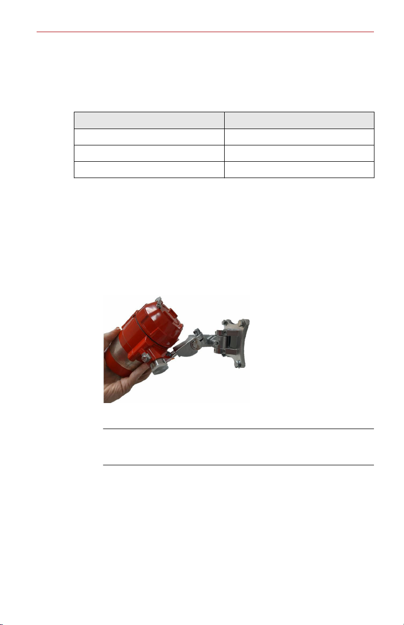
2. Insert location pins on the tilt mount into the openings on detector
housing.
3. Thread the holding screw and tighten it.
Note
To change the detector field of view, release the horizontal and
vertical locking screws.
4. Point the detector toward the protected area and ensure the view of
the area is unobstructed.
5. Secure the detector in that position by tightening the locking screws
on the tilt mount.
The detector is now correctly located, aligned, and ready to be
connected to the system.
Quick Start Guide 7
Page 8
Quick Start Guide May 2021
2.3 Open the back cover
Procedure
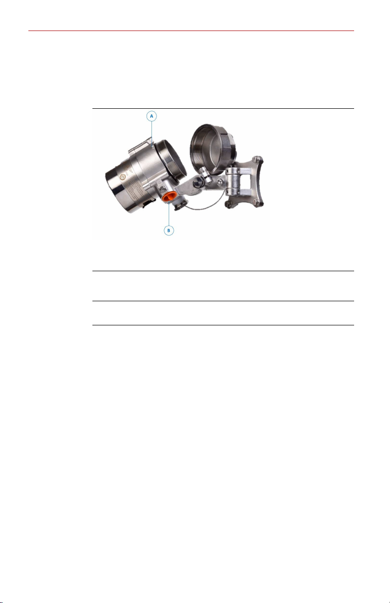
1. Loosen the back cover security screw.
A. Back cover security screw
B. Protective plug
2. Unscrew the back cover.
Note
The back cover is attached by a security cable.
3. Remove the protective plug.
8 Spectrex.net
Page 9
May 2021 Quick Start Guide
2.4 Wire terminals and ground cable
CAUTION
Improper wiring may damage the detector.
Procedure
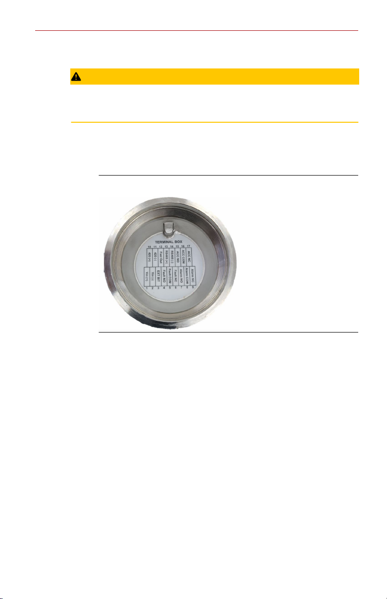
1. Connect the terminals according to Table 2-3.
The terminal details are also on the inside back cover.
Figure 2-1: Terminal Box
Quick Start Guide 9
Page 10

Quick Start Guide May 2021
Table 2-3: Terminal Box
Terminal Function
T1 24 Vdc (+)
T2 24 Vdc (-)
T3 External built-in test (BIT) switch
T4 Fault relay - normally open
T5 Fault relay
T6 Fault relay - normally closed
T7 Alarm relay - normally open
T8 Alarm relay
T9 Alarm relay - normally closed
T10 0-20 mA (+)
T11 0-20 mA (-)
T12 Alarm output
T13 RS485 (+)
T14 RS485 (-)
T15 Accessory relay - normally open
T16 Accessory relay
T17 Accessory relay - normally closed
(40/40D models)
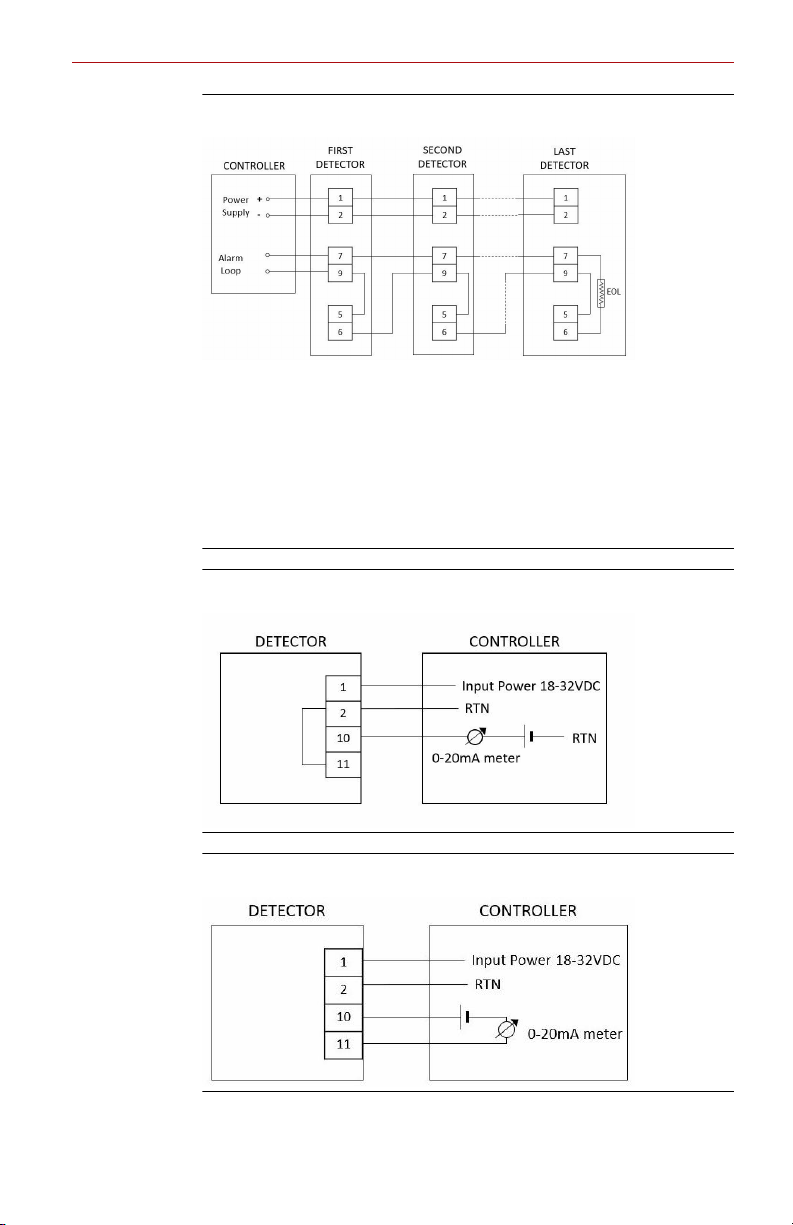
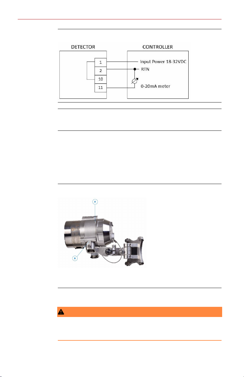
2. Use Figure 2-2, Figure 2-3, Figure 2-4, and Figure 2-5 for typical
wiring configurations.
10 Spectrex.net
Page 11
May 2021 Quick Start Guide
Figure 2-2: Typical Wiring for Four-Wire Controllers
A. Controller
B. First detector
C. Second detector
D. Last detector
E. Power supply
F. Alarm loop
G. End of line
Figure 2-3: Non-Isolated Sink (Three Wires)
Figure 2-4: Sink Four-Wire
Quick Start Guide 11
Page 12
Quick Start Guide May 2021
Figure 2-5: Source Three-Wire
Note
For additional configuration options, please refer to the Modbus
®
Manager Manual.
3. Check the wires for secure mechanical connection and press them
neatly against the terminal to prevent them from interfering while
closing the back cover.
4. Close the terminal compartment by screwing the back cover on to
the housing.
5. Tighten the back cover security screw.
Figure 2-6: Closing Security Screw
A. Back cover security screw
B. Ground cable connection point
6. Connect the ground cable.
WARNING
The terminal temperature may be higher than 185 °F (85 °C).
12 Spectrex.net
Page 13

May 2021 Quick Start Guide
CAUTION
To comply with EMC directive 2014/30/EU and protect against
interference caused by radio frequency interference (RFI) and
electromagnetic interference (EMI), shield the cable to the detector
and ground the detector. Ground the shield at the detector end.
Quick Start Guide 13
Page 14
Quick Start Guide May 2021
2.5 Install the protective cover
CAUTION
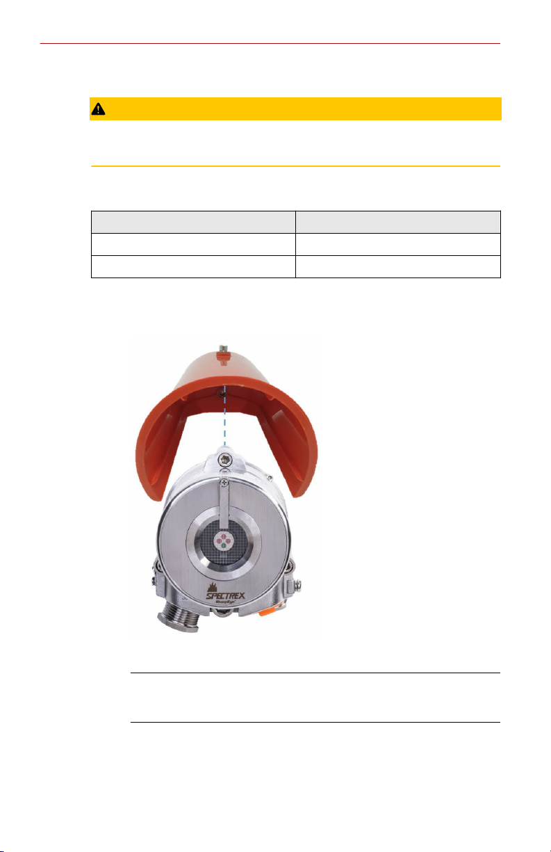
The protective cover should always be installed with the detector.
The protective cover is available in ABS plastic or stainless steel.
Table 2-4: Protective Cover
Material Part number
ABS plastic 00975-9000-0020
Stainless steel 00975-9000-0021
Procedure
1. Place the protective cover on top of the detector.
2. Secure the protective cover by tightening the screw.
Note
When installing the stainless steel protective cover, the same
installation instructions apply.
14 Spectrex.net
Page 15

May 2021 Quick Start Guide
3 Special conditions for safe use
• Lids securing fasteners shall be property class A4 with a yield stress of
344N/mm2.
• Units may be painted or fitted with optional accessories, some of which
are made of non-metallic material or have a non-metallic coating which
could potentially generate an ignition-capable level of electrostatic
charge under certain extreme conditions (such as high pressure steam)
which might cause a build-up of electrostatic charges on the nonconducting surfaces. Additionally, cleaning of the equipment should
only be done with a damp cloth.
• Under rated conditions, the cable entries reach a temperature exceeding
158 °F (70 °C), and the branching point exceeds a temperature of 176 °F
(80 °C); this shall be considered when installing cable glands, and only
cables that have temperature ratings suitable for the application shall be
used.
• Flameproof joints are not intended to be repaired.
• The SharpEye 40/40 Series Flame Detectors can be fitted with an
unmolded (non-encapsulated) end of line (EOL) resistor. Such a resistor
can only be fitted into the flameproof "Ex d" compartment as indicated in
the instructions. The EOL resistor shall be rated at 1.56 kΩ, 1 W
minimum.
To reduce the risk of ignition of a flammable or explosive atmosphere,
strictly adhere to the following statements:
WARNING
Do not open when energized.
Do not open when an explosive atmosphere is present.
Temperature at branching point may exceed 212 °F (100 °C).
CAUTION
Potential electrostatic charging hazard
See instructions.
Quick Start Guide 15
Page 16
Quick Start Guide May 2021
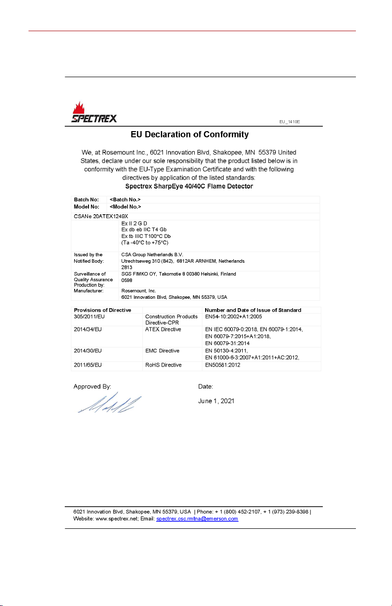
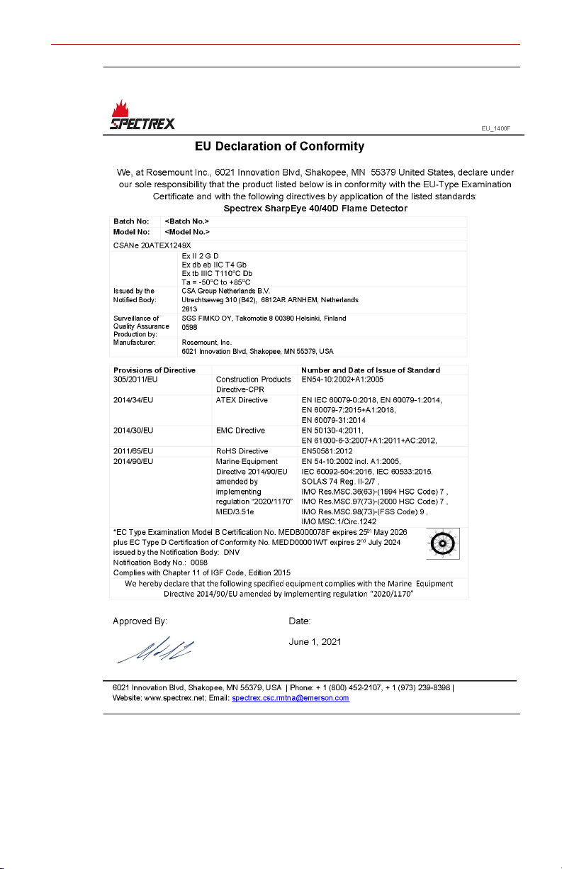
4 Declarations of Conformity
Figure 4-1: SharpEye 40/40C
16 Spectrex.net
Page 17
May 2021 Quick Start Guide
Figure 4-2: SharpEye 40/40D
Quick Start Guide 17
Page 18

Quick Start Guide May 2021
5 Reference data
To view current SharpEye 40/40 ordering information, specifications, and
drawings:
Procedure
1. Go to https://spectrex.net/en-us/flame-gas-detectors/flame-
detectors/40-40-series.
2. Select the appropriate flame detector.
3. For installation drawings, click Drawings and Schematics and select
the appropriate document.
4. For ordering information, specifications, and dimensional drawings,
click Data Sheets & Bulletins and select the appropriate Product Data
Sheet.
18 Spectrex.net
Page 19

May 2021 Quick Start Guide
Quick Start Guide 19
Page 20

*00925-0200-9975*
00925-0200-9975, Rev. AA
Quick Start Guide
May 2021
For more information:
©
2021 Emerson. All rights reserved.
Spectrex is a mark of one of the Emerson
family of companies. All other marks are
the property of their respective owners.
www.emerson.com
 Loading...