

Page 1
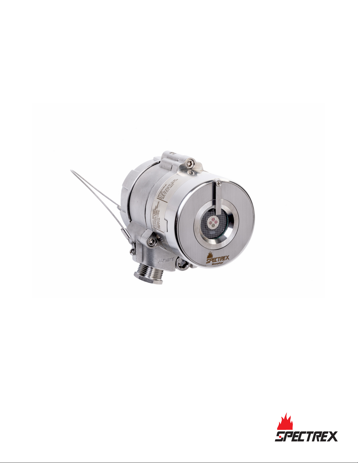
Reference Manual
00909-0100-4975, Rev AB
December 2021
Spectrex SharpEye™ 40/40C and 40/40D Series
Flame Detectors
Page 2

Legal notice
The device described in this document is the property of Emerson.
No part of the hardware, software, or documentation may be reproduced, transmitted, transcribed, stored in a retrieval system,
or translated into any language or computer language, in any form or by any means, without prior written permission from
Emerson.
While great efforts have been made to ensure the accuracy and clarity of this document, Emerson assumes no liability resulting
from any omissions in this document or from misuse of the information obtained herein. The information in this document has
been carefully checked and is believed to be entirely reliable with all of the necessary information included. Emerson reserves the
right to make changes to any products described herein to improve reliability, function, or design and reserves the right to revise
this document and make changes from time to time in content hereof with no obligation to notify any persons of revisions or
changes. Emerson does not assume any liability arising out of the application or any use of any product or circuit described herein;
neither does it convey license under its patent rights or the rights of others.
Warranty
Limited Warranty . Subject to the limitations contained in Section 2 (Limitation of Remedy and Liability) herein, Seller
1.
warrants that (a) the licensed firmware embodied in the Goods will execute the programming instructions provided by
Seller; (b) that the Goods manufactured by Seller will be free from defects in materials or workmanship under normal use
and care; and (c) Services will be performed by trained personnel using proper equipment and instrumentation for the
particular Service provided. The foregoing warranties will apply until the expiration of the applicable warranty period.
Sensors and detectors are warranted against defective parts and workmanship for 36 months for SharpEye 40/40C
models and 60 months for SharpEye 40/40D models from the date of purchase.
Products purchased by Seller from a third party for resale to Buyer (Resale Products) shall carry only the warranty
extended by the original manufacturer. Buyer agrees that Seller has no liability for Resale Products beyond making a
reasonable commercial effort to arrange for procurement and shipping of the Resale Products. If Buyer discovers any
warranty defects and notifies Seller thereof in writing during the applicable warranty period, Seller shall, at its option, (i)
correct any errors that are found by Seller in the firmware or Services; (ii) repair or replace FOB point of manufacture that
portion of the Goods found by Seller to be defective; or (iii) refund the purchase price of the defective portion of the
Goods/Services. All replacements or repairs necessitated by inadequate maintenance; normal wear and usage; unsuitable
power sources or environmental conditions; accident; misuse; improper installation; modification; repair; use of
unauthorized replacement parts; storage or handling; or any other cause not the fault of Seller, are not covered by this
limited warranty and shall be replaced or repaired at Buyer's sole expense, and Seller shall not be obligated to pay any
costs or charges incurred by Buyer or any other party except as may be agreed upon in writing in advance by Seller. All
costs of dismantling, reinstallation, freight, and the time and expenses of Seller's personnel and representatives for site
travel and diagnosis under this limited warranty clause shall be borne by Buyer unless accepted in writing by Seller. Goods
repaired and parts replaced by Seller during the warranty period shall be in warranty for the remainder of the original
warranty period or 90 days, whichever is longer. This limited warranty is the only warranty made by Seller and can be
amended only in a writing signed by an authorized representative of Seller. The limited warranty herein ceases to be
effective if Buyer fails to operate and use the Goods sold hereunder in a safe and reasonable manner and in accordance
with any written instructions from the manufacturers. THE WARRANTIES AND REMEDIES SET FORTH ABOVE ARE
EXCLUSIVE. THERE ARE NO REPRESENTATIONS OR WARRANTIES OF ANY KIND, EXPRESSED OR IMPLIED, AS TO
MERCHANTABILITY, FITNESS FOR PARTICULAR PURPOSE, OR ANY OTHER MATTER WITH RESPECT TO ANY OF THE GOODS
OR SERVICES.
Limitation of Remedy and Liability SELLER SHALL NOT BE LIABLE FOR DAMAGES CAUSED BY DELAY IN PERFORMANCE. THE
2.
REMEDIES OF BUYER SET FORTH IN THE AGREEMENT ARE EXCLUSIVE. IN NO EVENT, REGARDLESS OF THE FORM OF THE
CLAIM OR CAUSE OF ACTION (WHETHER BASED IN CONTRACT INFRINGEMENT, NEGLIGENCE, STRICT LIABILITY, OTHER
TORT, OR OTHERWISE), SHALL SELLER'S LIABILITY TO BUYER AND/OR BUYER'S CUSTOMERS EXCEED THE PRICE TO BUYER
OF THE SPECIFIC GOODS MANUFACTURED OR SERVICES PROVIDED BY SELLER GIVING RISE TO THE CLAIM OR CAUSE OF
ACTION. BUYER AGREES THAT IN NO EVENT SHALL SELLER'S LIABILITY TO BUYER AND/OR BUYER'S CUSTOMERS EXTEND
TO INCLUDE INCIDENTAL, CONSEQUENTIAL, OR PUNITIVE DAMAGES. THE TERM "CONSEQUENTIAL DAMAGES" SHALL
INCLUDE, BUT NOT BE LIMITED TO, LOSS OF ANTICIPATED PROFITS, REVENUE OR USE AND COSTS INCURRED INCLUDING
WITHOUT LIMITATION FOR CAPITAL, FUEL AND POWER, AND CLAIMS OF BUYER'S CUSTOMERS.
Technical support
To get technical support for this product, contact your local Rosemount representative or the Rosemount Technical Support
department at +1 866 347 3427 or [email protected]
Abbreviations and acronyms
Abbreviation or acronym
ATEX Atmospheric explosives
Definition
2
Page 3

Abbreviation or acronym Definition
AWG American wire gauge
BIT Built-in test
EMC Electromagnetic compatibility
EOL End of line
FOV Field of view
®
HART
Highway addressable remote transducer - communication protocol
IAD Immune at any distance
IECEx International Electrotechnical Commission Explosion
IPA Isopropyl alcohol
IR Infrared
JP5 Type of jet fuel
Latching Refers to relays remaining in the ON state even after the ON condition has been
removed.
LED Light emitting diode
LPG Liquified petroleum gas
mA Milliamps (0.001 amps)
®
Modbus
Master-slave messaging structure
N.C. Normally closed
N.O. Normally open
N/A Not applicable
NFPA National Fire Protection Association
NPT National pipe thread
RS485 Communication protocol allowing bi-directional communication
PN Part number
SIL Safety integrity level
UNC Unified coarse thread
Vac Volts alternating current
Vdc Volts direct current
3
Page 4

4
Page 5

Reference Manual Contents
00909-0100-4975 December 2021
Contents
Chapter 1 Introduction.............................................................................................................. 7
1.1 Product overview.........................................................................................................................7
1.2 Models.........................................................................................................................................7
Chapter 2 Installation...............................................................................................................11
2.1 Installation guidelines................................................................................................................11
2.2 Preparation for use.................................................................................................................... 11
2.3 Attach detector to tilt mount.....................................................................................................15
2.4 Open the back cover..................................................................................................................16
2.5 Wire terminals and ground cable............................................................................................... 16
2.6 Install the protective cover.........................................................................................................21
2.7 Aim the detector........................................................................................................................22
2.8 Changing default detector settings ...........................................................................................22
Chapter 3 Operation................................................................................................................ 25
3.1 Power up the detector............................................................................................................... 25
3.2 Testing procedures....................................................................................................................25
Chapter 4 Initial setup..............................................................................................................27
4.1 Continuous feature test............................................................................................................. 27
4.2 Response to fault indication.......................................................................................................27
4.3 Built-in-test (BIT)........................................................................................................................27
Chapter 5 Maintenance............................................................................................................29
5.1 Keeping maintenance records................................................................................................... 29
5.2 Clean the detector.....................................................................................................................29
Chapter 6 Troubleshooting...................................................................................................... 31
6.1 Light-emitting diode (LED) is off, fault relay is open, 0-20 mA shows 0 mA, analog voltage
output is 0 V................................................................................................................................31
6.2 Light-emitting diode (LED) flashes yellow at 4 Hz, fault relay is open, 0-20 mA shows 1 mA.......31
6.3 Light-emitting diode (LED) flashes yellow at 4 Hz, relay is open, 0-20 mA shows 2 mA...............31
6.4 Light-emitting diode (LED) constantly red, alarm relay energized, 0-20 mA indicates alarm.......32
6.5 No HART® communication, 0-20 mA shows 0 mA......................................................................32
Chapter 7 Specifications...........................................................................................................33
7.1 Technical specifications............................................................................................................. 33
7.2 Electrical specifications..............................................................................................................38
7.3 Mechanical specifications.......................................................................................................... 39
Appendix A Reference data......................................................................................................... 41
A.1 Ordering information, specifications, and dimensional drawings...............................................41
SharpEye 40/40 5
Page 6

Contents Reference Manual
December 2021 00909-0100-4975
A.2 Product certifications and installation drawings.........................................................................41
Appendix B FM fuel test responses ............................................................................................. 43
Appendix C Immunity to false alarm sources...............................................................................47
6 Spectrex.net
Page 7

Reference Manual
00909-0100-4975 December 2021
Introduction
1 Introduction
1.1 Product overview
The SharpEye 40/40 series is based on proven Spectrex technologies, including triple
infrared (IR3) and ultraviolet infrared (UV/IR). The SharpEye 40/40 series features
QuadSense™ technology, providing the fastest response to fire, longest distance
detection, and revolutionary UV/IR technology, coupled with superior immunity to false
alarms, functioning in harsh conditions with unparalleled reliability and durability.
The series is suited to meet the challenges of wide range of industrial and commercial
applications with long distance and fast response detection, providing superior protection
of high value property and personnel to keep a SharpEye on your safety.
Detection performance can be easily adapted to all environments, applications, and
requirements, by changing the detector’s configuration parameters. Adjusting these
parameters, as well as performing other maintenance and monitoring tasks, is possible by
means of RS-485-based Modbus® communication or HART® communication.
1.2 Models
The SharpEye 40/40 Flame Detectors are electro-optical devices designed to identify fire
events, enabling alarm activation. The detectors are intended for indoor or outdoor use
and can be used stand alone or connected to an alarm/automatic extinguishing system.
The SharpEye 40/40 series comprises the following detectors:
SharpEye 40/40C-I
The SharpEye 40/40C-I, a multispectrum Quad-sense™ flame detector, detects
hydrocarbon fuel and gas fires with enhanced performance, advanced long distance
detection of hydrocarbon fires, fast detection in under five seconds, and strengthened
reliability. The SharpEye 40/40C-I is based on proven triple infrared (IR3) technology,
ensuring high sensitivity with superior immunity to false alarms.
SharpEye 40/40C-M
The SharpEye 40/40C-M multispectrum Quad-sense IR flame detector is specifically
designed for the detection of hydrocarbon and hydrogen flames with enhanced
performance, advanced long distance detection of hydrogen and hydrocarbon fires, fast
detection in under five seconds, and strengthened reliability. The SharpEye 40/40C-M is
based on proven triple IR (IR3) technology, ensuring high sensitivity with superior
immunity to false alarms.
SharpEye 40/40C-LB
The SharpEye 40/40C-LB is a dual spectrum ultraviolet (UV)/IR flame detector, designed to
provide fast detection in under five seconds of a range of fires, such as hydrocarbon-based
fuel and gas, hyrdoxyl, hydrogen, metal, and inorganic.
SharpEye 40/40 7
Page 8

Introduction Reference Manual
December 2021 00909-0100-4975
SharpEye 40/40C-L4B
The SharpEye 40/40C-L4B is a dual spectrum UV/IR flame detector designed to provide
fast detection in under five seconds of hydrocarbon-based fuel and gas fires.
SharpEye 40/40D-I
The SharpEye 40/40D-I, an ultra-fast multispectrum Quad-sense IR3 flame detector,
provides superior, longest distance detection of hydrocarbon fires at up to 295.3 ft (90 m),
exceptional ultra-fast detection in under 50 msec, and unparalleled reliability. The
SharpEye 40/40D-I is based on proven Triple IR (IR3) technology, ensuring highest
sensitivity with best immunity to false alarms.
SharpEye 40/40D-M
The SharpEye 40/40D-M is a multispectrum Quad-sense IR flame detector that provides
superior, longest distance detection of hydrogen (at up to 164.0 ft (50 m)) and
hydrocarbon fires (at up to 295.3 ft (90 m)), exceptional ultra-fast detection in under 50
msec, and unparalleled reliability. The SharpEye 40/40D-M is designed to deal with the
challenges of invisible fires based on proven IR3 technology, ensuring highest sensitivity
with best immunity to false alarms.
SharpEye 40/40D-LB
The SharpEye 40/40D-LB is an ultra-fast UV/IR flame detector, which is able to detect in
under 20 msec and features a unique dual sensor with selectable UV and IR channels that
can be used separately or combined. The detector is designed to detect a range of fires,
such as hydrocarbon-based fuel and gas, hydroxyl, hydrogen, metal, and inorganic.
SharpEye 40/40D-L4B
The SharpEye 40/40D-L4B is an ultra-fast UV/IR flame detector that is able to detect in
under 20 msec, and features a unique dual sensor with selectable UV and IR channels that
can be used separately or combined. The detector is designed to detect hydrocarbonbased fuel and gas fires.
Table 1-1: SharpEye 40/40 Series General Technical Specifications
Spectral response Infrared and ultraviolet bands
Response time Varies according to model, typically under 5 seconds
Field of view Varies according to model, up to 100 degrees
Output 4-20 mA, relays, communication
Enclosure Stainless steel 316 or aluminum polyurethane painted
Operating voltage 18-32 Vdc
Maximum power rating 9.6 W
Relay contacts 2A/30 Vdc
Over voltage category 2
Relative humidity Non-condensing relative humidity up to 100%
8 Spectrex.net
Page 9

Reference Manual Introduction
00909-0100-4975 December 2021
CAUTION
If the product is used outside of specified limits, this voids the product certification, and
our company is not responsible for any incurred warranty expense.
Do not open this product, except for the terminal compartment as listed in this document,
under any circumstances.
The detector is not field-repairable. Any attempt to modify or repair the internal circuits or
change their settings will impair the system’s performance and void the product warranty.
Opening the attachment screws to dismantle the front part of the detector from
remaining parts is restricted and voids the product warranty.
SharpEye 40/40 9
Page 10

Introduction Reference Manual
December 2021 00909-0100-4975
10 Spectrex.net
Page 11

Reference Manual
00909-0100-4975 December 2021
Installation
2 Installation
2.1 Installation guidelines
Installation should comply with the National Fire Protection Association (NFPA) 72E or any
other local and international regulations and standards, as applicable to flame detectors
and installation of Ex approved products. To ensure optimal performance and efficient
installation, consider the following guidelines.
Sensitivity
To determine the level of sensitivity, consider the following:
• Size of fire at the required distance to be detected
• Type of flammable materials
• Proximity to false alarm sources
Wiring
The wire gauge must be designed according to the distance from the detector to the
controller and the number of detectors on the same power line.
To fully comply with EMC directive and protect against interference caused by RFI and EMI,
the cable to the detector must be shielded and the detector must be grounded. The shield
should be grounded at the detector end.
Spacing and location
The number of detectors and their locations in the protected area are determined by:
• Size of the protected area
• Sensitivity of the detectors
• Obstructed lines of sight
• Cone of view of the detectors
Environment
Dust, snow, or rain can reduce the detector’s sensitivity and require more maintenance
activities.
The presence of high intensity emission sources may affect sensitivity.
2.2 Preparation for use
The installation sequence may vary according to the physical structure of the site.
Note
Installation steps are also detailed in the Quick Start Guide supplied with the detector.
The following tools are required for installation. These are standard tools and are not
supplied with the detector.
SharpEye 40/40 11
Page 12
Installation Reference Manual
December 2021 00909-0100-4975
Table 2-1: Required tools
Tool Function
Hex key 1.5 mm Fasten back cover security screw.
Hex key 6 mm Adjust the tilt mount.
Hex key 10 mm Affix the detector to the tilt mount.
Hex key ⅛-in Attach protective cover to detector.
Flat screwdriver 6 mm Connect ground terminal.
Flat screwdriver 2.5 mm Connect wires to the terminal blocks.
Hex key ⅜-in Stop plug ¾-in NPT.
Open wrench 28 mm Stop plug M25 only.
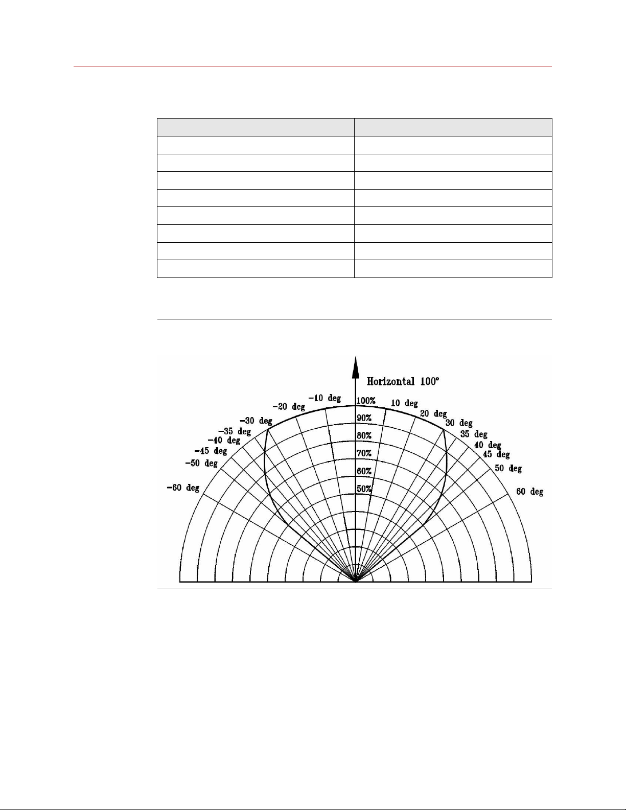
2.2.1 Field of view
Figure 2-1: Horizontal field of view forSharpEye 40/40C-I, C-LB, C-L4B, D-I, D-LB, and
D-L4B
12 Spectrex.net
Page 13
Reference Manual Installation
00909-0100-4975 December 2021
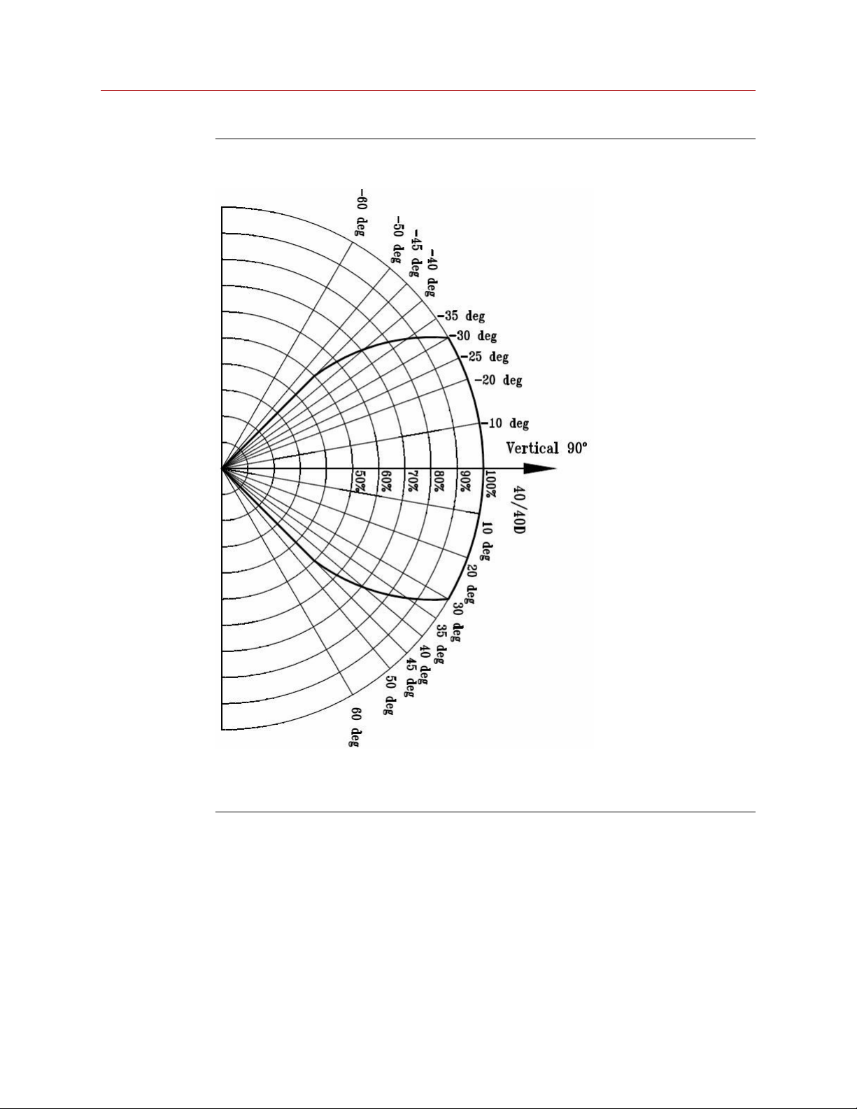
Figure 2-2: Vertical Field of View for SharpEye 40/40C-I, C-LB, C-L4B, D-I, D-LB, and DL4B
• +50 ° (down)
• -45 ° (up)
Gasoline
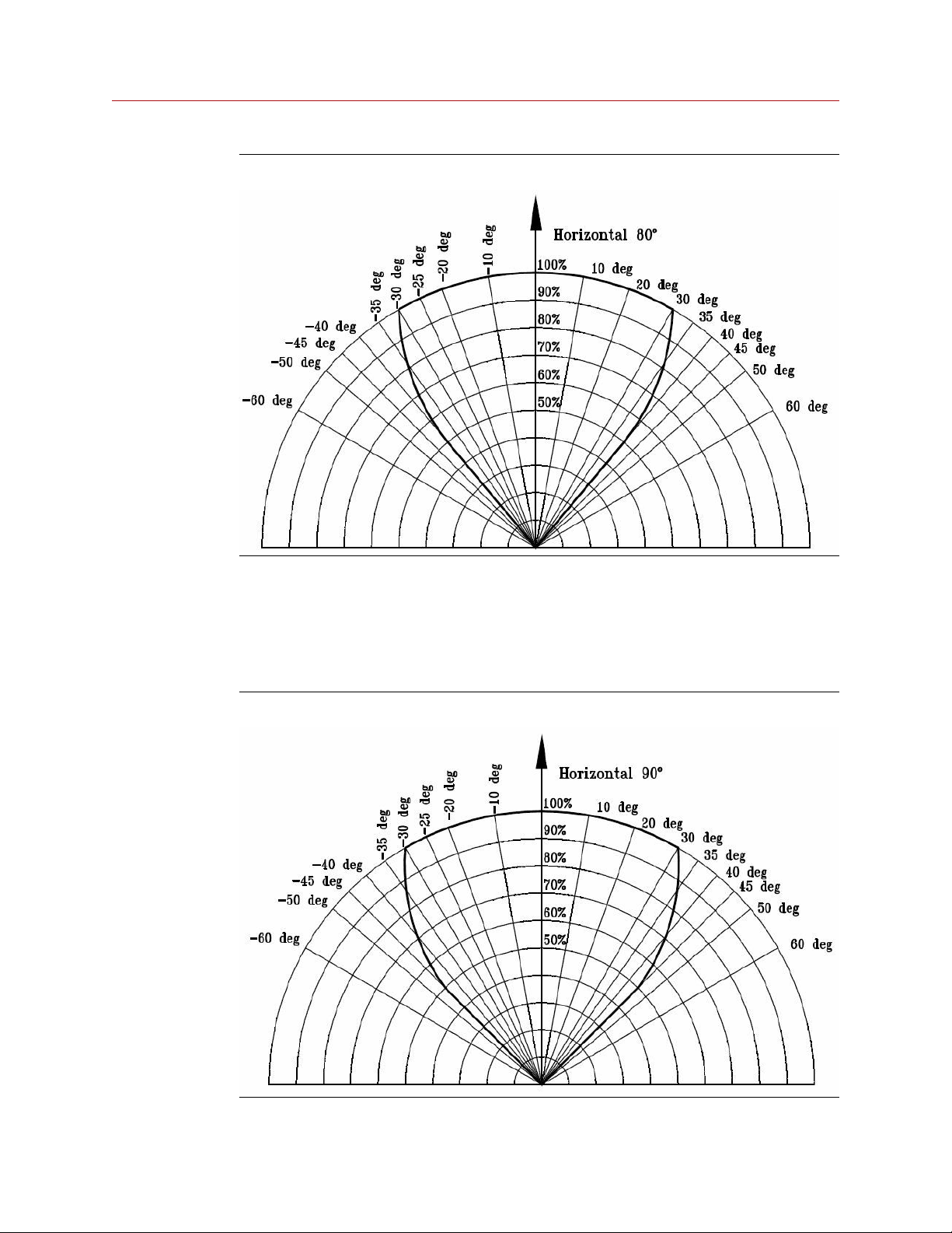
For SharpEye 40/40C-M and D-M
• Horizontal: 80 °
• Vertical: 80 °
SharpEye 40/40 13
Page 14
Installation Reference Manual
December 2021 00909-0100-4975
Figure 2-3: Vertical and horizontal field of view for gasoline
Hydrogen
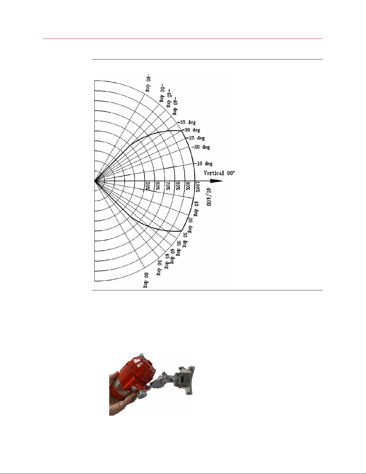
For SharpEye 40/40C-M and D-M
• Horizontal: 90°
• Vertical: 90°
Figure 2-4: Horizontal field of view for hydrogen
14 Spectrex.net
Page 15
Reference Manual
00909-0100-4975 December 2021
Figure 2-5: Vertical field of view for hydrogen
Installation
2.3 Attach detector to tilt mount
Procedure
1. Unpack the detector.
2. Insert location pins on the tilt mount into the openings on detector housing.
3. Thread the holding screw and tighten it.
SharpEye 40/40 15
Page 16
Installation Reference Manual
December 2021 00909-0100-4975
Note
To change the detector field of view, release the horizontal and vertical locking
screws.
4. Point the detector toward the protected area and ensure the view of the area is
unobstructed.
5. Secure the detector in that position by tightening the locking screws on the tilt
mount.
The detector is now correctly located, aligned, and ready to be connected to the
system.
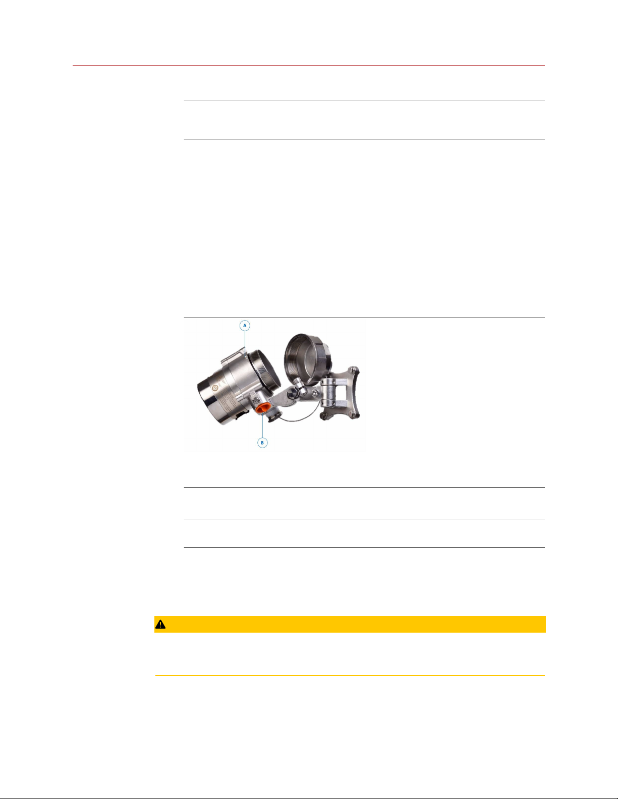
2.4 Open the back cover
Procedure
1. Loosen the back cover security screw.
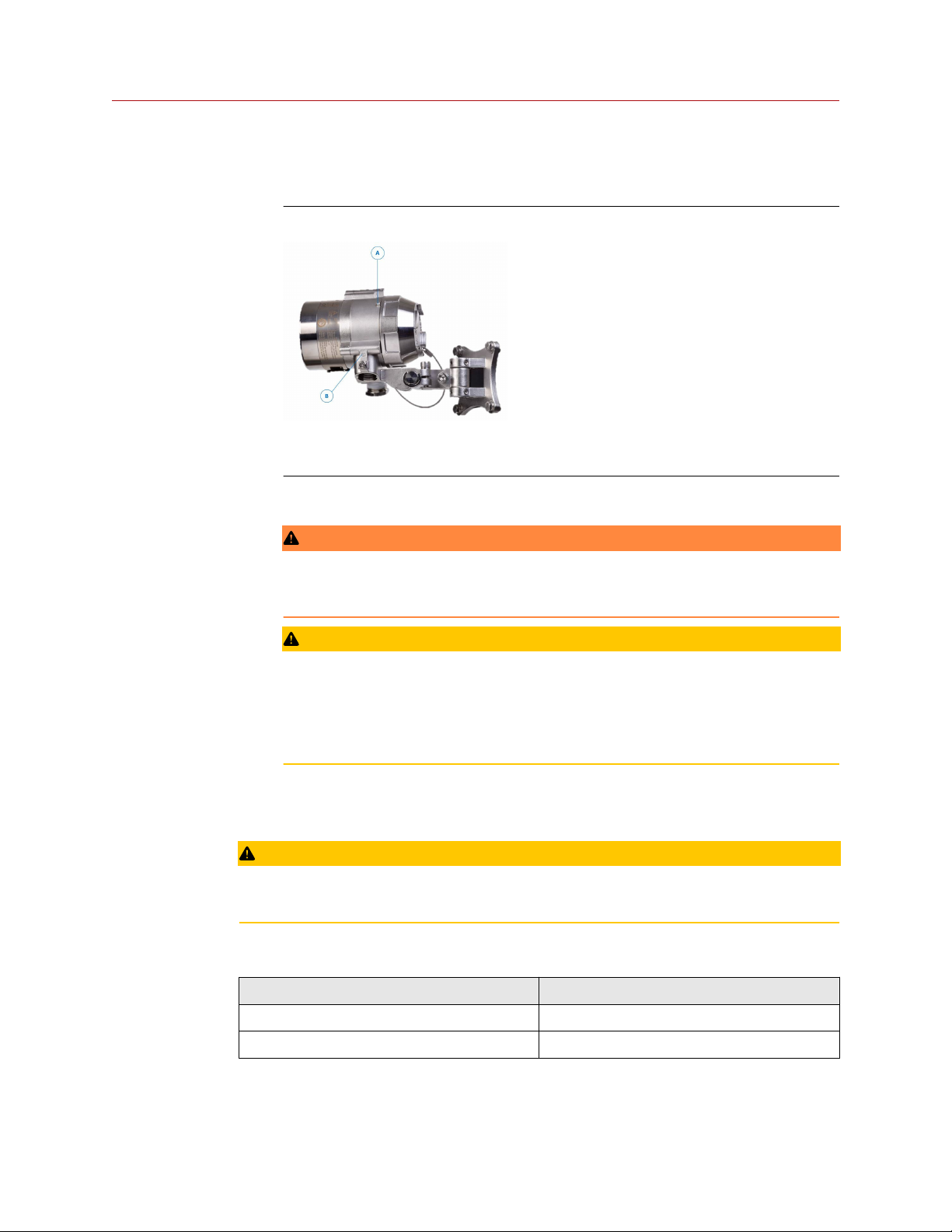
A. Back cover security screw
B. Protective plug
2. Unscrew the back cover.
Note
The back cover is attached by a security cable.
3. Remove the protective plug.
2.5 Wire terminals and ground cable
CAUTION
Improper wiring may damage the detector.
16 Spectrex.net
Page 17

Reference Manual Installation
00909-0100-4975 December 2021
Procedure
1. Connect the terminals according to Table 2-2.
The terminal details are also on the inside back cover.
Figure 2-6: Terminal box
SharpEye 40/40 17
Page 18

Installation Reference Manual
December 2021 00909-0100-4975
Table 2-2: Terminal box
Terminal Function
T1 24 Vdc (+)
T2 24 Vdc (-)
T3 External built-in test (BIT) switch
T4 Fault relay - normally open
T5 Fault relay
T6 Fault relay - normally closed
T7 Alarm relay - normally open
T8 Alarm relay
T9 Alarm relay - normally closed
T10 0-20 mA (+)
T11 0-20 mA (-)
T12 Alarm output
(40/40D models)
T13 RS485 (+)
T14 RS485 (-)
T15 Accessory relay - normally open
T16 Accessory relay
T17 Accessory relay - normally closed
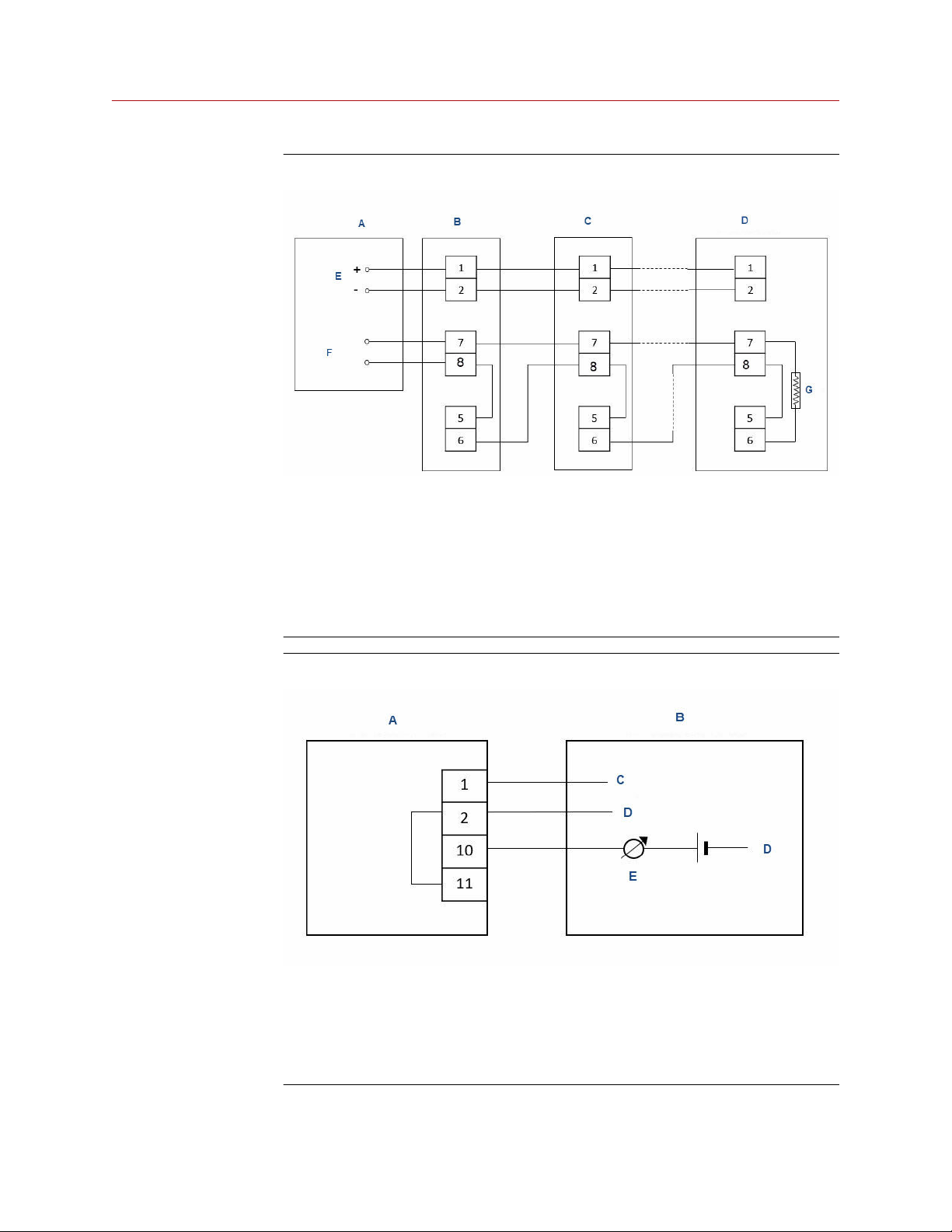
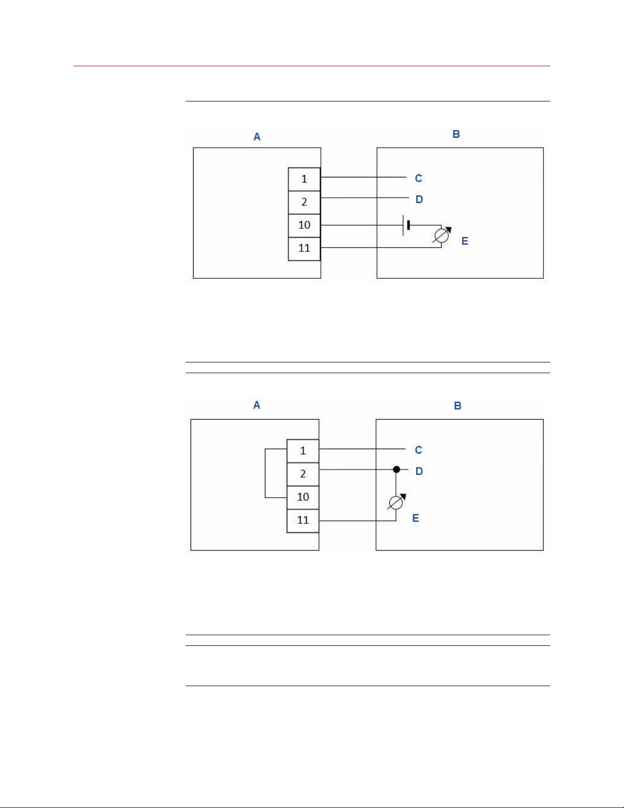
2. Use Figure 2-7, Figure 2-8, Figure 2-9, and Figure 2-10 for typical wiring
configurations.
18 Spectrex.net
Page 19
Reference Manual
Installation
00909-0100-4975 December 2021
Figure 2-7: Typical wiring for four-wire controllers
A. Controller
B. First detector
C. Second detector
D. Last detector
E. Power supply
F. Alarm loop
G. End of line
Figure 2-8: Non-isolated sink (three wires)
A. Detector
B. Controller
C. Input power: 18 to 32 Vdc
D. Return
E. 0-20 mA meter
SharpEye 40/40 19
Page 20
Installation
Reference Manual
December 2021 00909-0100-4975
Figure 2-9: Sink four-wire
A. Detector
B. Controller
C. Input power: 18 to 32 Vdc
D. Return
E. 0-20 mA meter
Figure 2-10: Source three-wire
A. Detector
B. Controller
C. Input power: 18-32 Vdc
D. Return
E. 0-20 mA meter
Note
For additional configuration options, please refer to the Spectrex SharpEye 40/40C
and D Series Flame Detectors Modbus® Manager Manual.
3. Check the wires for secure mechanical connection and press them neatly against
the terminal to prevent them from interfering while closing the back cover.
20 Spectrex.net
Page 21
Reference Manual Installation
00909-0100-4975 December 2021
4. Close the terminal compartment by screwing the back cover on to the housing.
5. Tighten the back cover security screw.
Figure 2-11: Closing security screw
A. Back cover security screw
B. Ground cable connection point
6. Connect the ground cable.
WARNING
The terminal temperature may be higher than 185 °F (85 °C).
CAUTION
To comply with EMC directive 2014/30/EU and protect against interference caused
by radio frequency interference (RFI) and electromagnetic interference (EMI), shield
the cable to the detector and ground the detector. Ground the shield at the
detector end.
2.6 Install the protective cover
CAUTION
Always install the protective cover with the detector.
The protective cover is available in ABS plastic or stainless steel.
Table 2-3: Protective cover
Material Part number
ABS plastic 00975-9000-0020
Stainless steel 00975-9000-0021
SharpEye 40/40 21
Page 22
Installation
December 2021 00909-0100-4975
Procedure
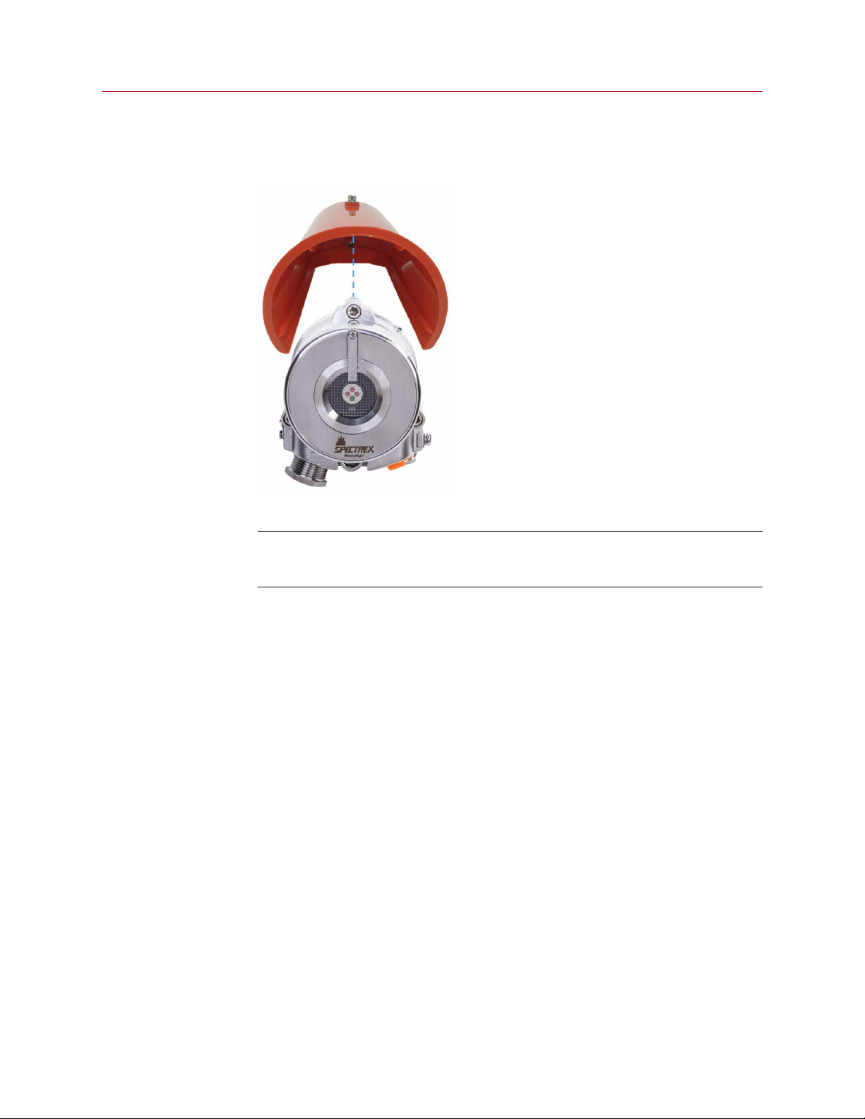
1. Place the protective cover on top of the detector.
Reference Manual
2. Secure the protective cover by tightening the screw.
Note
When installing the stainless steel protective cover, the same installation
instructions apply.
2.7 Aim the detector
Aim the detector toward the center of the detection zone and make sure you have a
completely unobstructed view of the protected area.
Emerson recommends positioning the detector tilted down at a 45° angle to maximize
coverage and prevent accumulation of dust and dirt.
Do not begin installation until all conceivable considerations regarding detection location
have been taken into account.
2.8 Changing default detector settings
The Main settings that can be modified using the Modbus® Manager or HART
communication include:
• Sensitivity
• Response time
®
• Heated optics functionality
• Alarm delay
• Accessory relay options
22 Spectrex.net
Page 23

Reference Manual Installation
00909-0100-4975 December 2021
• Alarm latch
• Field of view integrity indication
Refer to the Spectrex SharpEye 40/40C and D Series Flame Detectors Modbus Manager
Manual or the Spectrex SharpEye 40/40C and D Series Flame Detectors HART Manual for
instructions on changing these settings.
SharpEye 40/40 23
Page 24

Installation Reference Manual
December 2021 00909-0100-4975
24 Spectrex.net
Page 25

Reference Manual
00909-0100-4975 December 2021
Operation
3 Operation
3.1 Power up the detector
Procedure
After connecting the detector to power, wait up to 60 seconds for the detector to
completed the initial start-up procedure.
Note
Turning on the detector initiates the following sequence of events:
a. The yellow light-emitting diode (LED) flashes at 4 Hz.
b. The built-in test (BIT) is executed.
c. BIT completes.
d. Detector enters Normal mode, indicated by:
• Flashing green LED at 1 Hz.
• Fault relay contacts closing.
• mA output is 4 mA (for models featuring analog [voltage] output, this will be 2
V).
3.2 Testing procedures
This section describes the explosion proof testing procedure using the Spectrex™ explosion
proof FS flame simulator series. The detector can also be tested using the Manual BIT.
Table 3-1: Flame Simulator Compatibility
Spectrex model flame simulator Suitable with detectors
FS-1100 Spectrex 40/40C-I and 40/40D-1
FS-1200 Spectrex 40/40C-LB, 40/40C-L4B, 40/40D-LB,
FS-1400 Spectrex 40/40C-M and 40/40D-M
To perform a flame simulator test:
1. Power up the system and wait for up to 60 seconds for the detector to return to
normal status.
The Power LED turns on.
and 40/40D-L4B
2. Ensure all indicators show normal (see Power up the detector).
For full instructions on operating a flame simulator test, see the relevant reference
manual.
SharpEye 40/40 25
Page 26

Operation Reference Manual
December 2021 00909-0100-4975
Table 3-2: Flame Simulator Reference Manuals
Flame simulator Reference manual
Spectrex FS-1100 TM380002
Spectrex FS-1200 TM380102
Spectrex FS-1400 TM380302
26 Spectrex.net
Page 27

Reference Manual
00909-0100-4975 December 2021
Initial setup
4 Initial setup
4.1 Continuous feature test
The detector is supplied with default settings, including a continuous feature test.
To change these settings, refer to the Spectrex SharpEye 40/40C and D Series Flame
Detectors Modbus® Manager Manual.
During normal operation, the detector tests itself continuously and indicates a fault if a
failure is found. This type of test complies with SIL-3 requirements.
The detector continuously tests:
• Input voltage level
• All internal regulator voltage level
• Voltage level status of sensor and sensor circuitry for noise or disconnection in the
electronic circuitry
• 0-20 mA level output
• Relays and heater operation
• Processor watch dog
• Software
• Memory
• Oscillator frequency
4.2 Response to fault indication
If a failure is found, the detector indicates by:
• Light-emitting diode (LED): yellow flashes (4 Hz)
• Fault relay opens
• 0-20 mA: 1 mA default
• Analog voltage output: 0 V output
(SharpEye 40/40D models only)
The fault indications remain until the detector is turned off. The fault indications return if
the fault is still found when power is restored.
4.3 Built-in-test (BIT)
The detector's BIT checks the following:
• Sensors
• Window cleanliness
SharpEye 40/40 27
Page 28

Initial setup Reference Manual
December 2021 00909-0100-4975
• Electronic circuitry
The detector can be set to perform the BIT in the following modes:
• Automatically and manually
• Manually only
BIT operation
The BIT is intended to check optical integrity and electronic circuitry. The detector's status
remains unchanged if the result of a BIT is the same as the current status (Normal or BIT
Fault). The detector’s status changes if the BIT differs from the current status.
Note
In BIT Fault status, the detector can continue to detect a fire in most cases.
Automatic BIT
The detector automatically performs a BIT every 15 minutes. A successful BIT sequence
does not activate any indicator. The BIT interval can be modified if required by the
customer using the RS-485 Modbus® Manager or HART® communicator. In case of a BIT
fault, this sequence continues until a successful BIT occurs, when the detector resumes
normal operation.
• As result of successful automatic/manual BIT, the fault relay remains energized.
• As result of unsuccessful automatic/manual BIT, the fault relay de-energizes.
Manual BIT
You can initiate manual BIT using the Modbus® Manager or HART® communicator.
Connecting terminal 3 to ground also initiates manual BIT. Alarm duration during manual
BIT is configurable using the Modbus Manager or HART communicator.
28 Spectrex.net
Page 29

Reference Manual Maintenance
00909-0100-4975 December 2021
5 Maintenance
5.1 Keeping maintenance records
Record all maintenance operations performed on a detector in accordance with site
guidance and requirements.
5.2 Clean the detector
Procedure
1. Disconnect power from the flame detector.
2. Wipe the detector housing with clean water and a damp cloth.
CAUTION
Do not use a brush or sharp tools.
3. Identify where dust, dirt, or moisture accumulates on the detector window.
a) Clean with a soft optical cloth.
b) Rinse with clean water.
SharpEye 40/40 29
Page 30

Maintenance Reference Manual
December 2021 00909-0100-4975
30 Spectrex.net
Page 31

Reference Manual Troubleshooting
00909-0100-4975 December 2021
6 Troubleshooting
6.1 Light-emitting diode (LED) is off, fault relay is open, 0-20 mA shows 0 mA, analog voltage output is 0 V
Note
Analog voltage output applies to SharpEye 40/40D models only.
Potential cause
No power to the unit.
Recommended actions
1. Check that the operating voltage is correct, according to Electrical
specifications.
2. Check power polarity.
3. Check the terminal wiring.
6.2 Light-emitting diode (LED) flashes yellow at 4 Hz, fault relay is open, 0-20 mA shows 1 mA
Potential cause
Low voltage.
Recommended action
Check that the operating voltage is correct, according to Electrical specifications
Potential cause
Faulty detector.
Recommended action
Re-power the detector.
6.3 Light-emitting diode (LED) flashes yellow at 4 Hz, relay is open, 0-20 mA shows 2 mA
Potential cause
Built-in test (BIT) fault.
SharpEye 40/40 31
Page 32

Troubleshooting Reference Manual
December 2021 00909-0100-4975
Recommended action
Ensure the detector window and reflector mirror are clean.
Potential cause
Faulty detector.
Recommended action
Re-power the detector.
6.4 Light-emitting diode (LED) constantly red, alarm relay energized, 0-20 mA indicates alarm
Potential cause
Existing alarm condition.
Recommended action
Check cause of alarm.
Potential cause
Alarm latched.
Recommended action
Ensure the alarm latch is not enabled in the detector settings.
Potential cause
Faulty detector.
Recommended action
Re-power the detector.
6.5 No HART® communication, 0-20 mA shows 0 mA
Potential
No HART is available at 0 mA level.
Recommended action
For Fault mode, the default indication is 1 mA. Configure this to 0 mA.
Emerson does not recommend this when using a HART connection in order to
preserve the HART communication.
32 Spectrex.net
Page 33

Reference Manual Specifications
00909-0100-4975 December 2021
7 Specifications
7.1 Technical specifications
Spectral response
SharpEye 40/40C-I
SharpEye 40/40C-M
SharpEye 40/40C-LB
SharpEye 40/40C-L4B
SharpEye 40/40D-I
SharpEye 40/40D-M
SharpEye 40/40D-LB
SharpEye 40/40D-L4B
Detection range per fuel (ft./m)
Note
The ranges shown are at highest sensitivity setting for 1 ft2 (0.1 m2) pan fire.
Table 7-1: SharpEye 40/40C Models
Fuel 40/40C-I 40/40C-M 40/40C-LB 40/40C-L4B
Gasoline 215 ft (65 m) 50 ft (15 m) 93 ft (28 m)
Four infrared (IR) bands between 4 μm and 5 μm
Four IR bands between 2 μm and 5 μm
Ultraviolet (UV): 0.185 - 0.260 μm
IR: 2.5-3.0 μm
UV: 0.185 - 0.260 μm
IR: 4.3 – 4.8μm
Four infrared (IR) bands between 4 μm and 5 μm
Four IR bands between 2 μm and 5 μm
Ultraviolet (UV): 0.185 - 0.260 μm
IR: 2.5-3.0 μm
UV: 0.185 - 0.260 μm
IR: 4.3 – 4.8μm
N-Heptane 215 ft (65 m) 50 ft (15 m) 93 ft (28 m)
Diesel fuel 150 ft (45 m) 37 ft (11 m) 70 ft (21 m)
Kerosene 150 ft (45 m) 37 ft (11 m) 70 ft (21 m)
Alcohol 95% 135 ft (40 m) 30 ft (9 m) 57 ft (17 m)
IPA 135 ft (40 m) 37 ft (11 m) 70 ft (21 m)
Methanol 135 ft (40 m) 30 ft (9 m) 57 ft (17 m)
Methane 150 ft (45 m) 30 ft (9 m) 60 ft (18 m)
LPG 150 ft (45 m) 30 ft (9 m) 60 ft (18 m)
Polypropylene 115 ft (35 m) 30 ft (9 m) 60 ft (18 m)
Paper 82.0 ft (25 m) 16.4 ft (5 m) 33 ft (10 m)
Hydrogen N/A 118.1 ft (36 m) 37 ft (11 m) N/A
SharpEye 40/40 33
Page 34

Specifications Reference Manual
December 2021 00909-0100-4975
Table 7-1: SharpEye 40/40C Models (continued)
Fuel 40/40C-I 40/40C-M 40/40C-LB 40/40C-L4B
Magnesium
(1)
alloy
N/A 16.4 ft (5 m) 33 ft (10 m)
Gun powder 141.1 ft (43 m) 32.8 ft (10 m) 91.9 ft (28 m)
Fireworks 23.0 ft (7 m) 5.25 ft (1.6 m) 9.8 ft (3 m)
Cooking oil 147.6 ft (45 m) 37 ft (11 m) 70 ft (21 m)
Mineral oil:
150 ft (45 m) 37 ft (11 m) 70 ft (21 m)
20w50
Wood 82 ft (25 m) 16 ft (5 m) 33 ft (10 m)
Ethylene glycol 118 ft (36 m) 12 ft (3.66 m) 23 ft (7 m)
Butyl acrylate 117 ft (36 m) 37 ft (11 m) 70 ft (21 m)
Vinyl acetate 117 ft (36 m) 37 ft (11 m) 70 ft (21 m)
Flammable
150 ft (45 m) 37 ft (11 m) 70 ft (21 m)
adhesive
Solvents 117 ft (36 m) 37 ft (11 m) 70 ft (21 m)
Oil paint 150 ft (45 m) 37 ft (11 m) 70 ft (21 m)
Jet fuel JP5 150 ft (45 m) 37 ft (11 m) 70 ft (21 m)
Jet fuel A1 150 ft (45 m) 37 ft (11 m) 70 ft (21 m)
(2)
Battery
200 ft (61 m) 39 ft (12 m) 75 ft (23 m)
(1) Contact Spectrex representative for guidance on detecting Magnesium alloy.
(2) One battery cell.
Table 7-2: SharpEye 40/40D Models
Fuel SharpEye
40/40D-I
Gasoline 300 ft (90 m) 93 ft (28 m)
N-Heptane 300 ft (90 m) 93 ft (28 m)
Diesel fuel 207 ft (63 m) 70 ft (21 m)
Kerosene 207 ft (63 m) 70 ft (21 m)
Alcohol 95% 185 ft (55 m) 57 ft (17 m)
Isopropyl alcohol
185 ft (55 m) 70 ft (21 m)
(IPA)
Methanol 185 ft (55 m) 57 ft (17 m)
Methane 207 ft (63 m) 60 ft (18 m)
Liquified
207 ft (63 m) 60 ft (18 m)
petroleum gas
(LPG)
Polypropylene 160 ft (49 m) 60 ft (18 m)
SharpEye
40/40D-M
SharpEye
40/40D-LB
SharpEye
40/40D-L4B
34 Spectrex.net
Page 35

Reference Manual Specifications
00909-0100-4975 December 2021
Table 7-2: SharpEye 40/40D Models (continued)
Fuel SharpEye
40/40D-I
Paper 112 ft (34 m) 10 ft (3 m)
Hydrogen N/A 164 ft (50 m) 70 ft (21 m) N/A
Magnesium
(1)
alloy
Gun powder 197 ft (60 m) 66 ft (20 m) 93 ft (28 m)
Fireworks 33 ft (10 m) 10 ft (3 m)
Cooking oil 207 ft (63 m) 70 ft (21 m)
Mineral oil: 20 w50207 ft (63 m) 70 ft (21 m)
Wood 112 ft (34 m) 33 ft (10 m)
Ethylene glycol 164 ft (50 m) 23 ft (7 m)
Butyl acrylate 246 ft (75 m) 70 ft (21 m)
Vinyl acetate 246 ft (75 m) 70 ft (21 m)
Flammable
adhesive
Solvents 246 ft (75 m) 70 ft (21 m)
Oil paint 207 ft (63 m) 70 ft (21 m)
N/A 33 ft (10 m)
207 ft (63 m) 70 ft (21 m)
SharpEye
40/40D-M
SharpEye
40/40D-LB
SharpEye
40/40D-L4B
Jet fuel JP5 207 ft (63 m) 70 ft (21 m)
Jet fuel A1 207 ft (63 m) 70 ft (21 m)
(2)
Battery
(1) Contact Emerson representative for guidance on detecting magnesium alloy.
(2) One battery cell.
279 ft (85 m) 75 ft (23 m)
Standard response time
Table 7-3: SharpEye 40/40C Models
Spectrex 40/40C-I Spectrex 40/40C-M Spectrex 40/40C-LB Spectrex 40/40C-L4B
Typically <5 sec
Table 7-4: SharpEye 40/40D Models
SharpEye 40/40D-I SharpEye 40/40D-M SharpEye 40/40D-LB SharpEye 40/40D-L4B
Typically <2 sec at 131 ft (40 m)
10 sec at 300 ft (90 m)
Typically 5 sec at 93 ft (28 m)
SharpEye 40/40 35
Page 36

Specifications Reference Manual
December 2021 00909-0100-4975
Ultra fast response time
Table 7-5: SharpEye 40/40C Models
Spectrex 40/40C-I Spectrex 40/40C-M Spectrex 40/40C-LB Spectrex 40/40C-L4B
N/A
Table 7-6: SharpEye 40/40D Models
SharpEye 40/40D-I SharpEye 40/40D-M SharpEye 40/40D-LB SharpEye 40/40D-L4B
Typically <1 sec at 100 ft (30 m) 20 msec for flash fire at 10 ft (3 m)
High speed response time
Table 7-7: SharpEye 40/40C Models
Spectrex 40/40C-I Spectrex 40/40C-M Spectrex 40/40C-LB Spectrex 40/40C-L4B
N/A
Table 7-8: SharpEye 40/40D Models
SharpEye 40/40D-I SharpEye 40/40D-M SharpEye 40/40D-LB SharpEye 40/40D-L4B
50 msec for 1 ft2 (0.1 m2) diameter sphere LPGair mixture explosion at 66 ft (20 m)
50 msec for 1 ft2 (0.1 m2) diameter sphere LPGair mixture explosion at 33 ft (10 m)
Sensitivity ranges
Note
All distances relate to detection of a 1 ft2 (0.1 m2) n-heptane fire
Table 7-9: SharpEye 40/40C Models
Spectrex 40/40C-I Spectrex 40/40C-M Spectrex 40/40C-LB Spectrex 40/40C-L4B
Five ranges:
• 10 ft (3 m)
• 50 ft (15 m)
• 100 ft (30 m)
• 150 ft (45 m)
• 215 ft (65 m)
Two ranges:
• 10 ft (3 m)
• 50 ft (15 m)
Three ranges:
• 10 ft (3 m)
• 50 ft (15 m)
• 92 ft (28 m)
36 Spectrex.net
Page 37

Reference Manual Specifications
00909-0100-4975 December 2021
Table 7-10: SharpEye 40/40D Models
SharpEye 40/40D-I SharpEye 40/40D-M SharpEye 40/40D-LB SharpEye 40/40D-L4B
Six ranges:
• 10 ft (3 m)
• 50 ft (15 m)
• 100 ft (30 m)
• 150 ft (45 m)
• 215 ft (65 m)
• 300 ft (90 m)
Three ranges:
• 10 ft (3 m)
• 50 ft (15 m)
• 92 ft (28 m)
Field of view
Table 7-11: SharpEye 40/40C Models
Spectrex 40/40C-I Spectrex 40/40C-M Spectrex 40/40C-LB Spectrex 40/40C-L4B
H: 100°
V: 95°
H: 100°
V: 95°
Hydrogen:
H: 90°
V: 90°
Other fuels:
H: 80°
V: 80°
H: 100°
V: 95°
H: 100°
V: 95°
Table 7-12: SharpEye 40/40D Models
SharpEye 40/40D-I SharpEye 40/40D-M SharpEye 40/40D-LB SharpEye 40/40D-L4B
Horizontal: 100°
Vertical: 95°
Hydrogen
Horizontal: 90°
Vertical: 90°
Other fuels
Horizontal: 80°
Vertical: 80°
Horizontal: 100°
Vertical: 95°
Temperature range (operating and storage)
Table 7-13: SharpEye 40/40C Models
Spectrex 40/40C-I Spectrex 40/40C-M Spectrex 40/40C-LB Spectrex 40/40C-L4B
-40 °F (-40 °C) to 167 °F (75 °C)
Table 7-14: SharpEye 40/40D Models
SharpEye 40/40D-I SharpEye 40/40D-M SharpEye 40/40D-LB SharpEye 40/40D-L4B
-76 °F (-60 °C) to 185 °F (85 °C)
Humidity
Non-condensing relative humidity up to 100 percent.
SharpEye 40/40 37
Page 38

Specifications Reference Manual
December 2021 00909-0100-4975
7.2 Electrical specifications
The electrical specifications apply to all models unless stated otherwise.
Operating voltage
Power consumption
Cable entries
Electrical input
protection
Electromagnetic
capability
Electrical interface
Electrical input protection
The input circuit is protected against voltage-reversed polarity, voltage transients, surges,
and spikes according to EN 54-10.
Outputs
Relays
Analog
0-20 mA
(stepped)
Alarm, fault, and auxiliary
SPST volt-free contacts rated 2A at 30 Vdc
5 V at detection, 0 V at fault, 2 V at normal
SharpEye 40/40C Models
24 Vdc nominal (18-32 Vdc)
Standby: Max. 3 W (8 W with heated window)
Alarm: Max. 4.2 W (9.6 W with heated window)
2 x ¾-in - 14 NPT conduits or 2 x M25 x 1.5 mm International
Organization for Standardization (ISO)
According to EN 50130
Electromagnetic interference/Radio frequency interference
(EMI/RFI) protected to EN61000-6-3 and EN 50130
The detector includes 17 terminals, one wiring option.
Fault: 0 +1 mA
BIT fault: 2mA ± 0.3mA
Normal: 4mA ± 0.3mA
Warning: 16mA ± 0.3mA
Alarm: 20mA ± 0.3mA
SharpEye 40/40D Models
Heated optics
The front window can be heated to improve performance in ice, condensation, and snow
conditions. The heater increases the temperature of the optical surface by 5 °C to 25 °C
above the ambient temperature
Off
(1) SharpEye 40/40D models have a low power heater option
38 Spectrex.net
Optics are not heated
(1)
. The heated optics can be configured in three ways:
Fault: 0 +1 mA
Built-in test (BIT) Fault: 2 mA ± 0.3 mA
Normal: 4 mA ± 0.3 mA
Warning: 16 mA ± 0.3 mA
Alarm: 20 mA ± 0.3 mA
Page 39

Reference Manual Specifications
00909-0100-4975 December 2021
On
Auto (default)
Note
In Auto mode, the starting heat temperature can be defined between 32 °F (0 °C) and 95 °F
(35 °C). The detector stops heating the window when the temperature is 15 °C above the
start temperature.
Optics are continuously heated
Operated only when the change of temperature requires the heating
7.3 Mechanical specifications
Enclosure options
SharpEye 40/40C
Models
SharpEye 40/40D
Models
Tilt mount
Stainless steel 316 with electropolish finish
Detector dimensions
Heavy duty copper free aluminum (less than 1%), polyurethane
painted
Stainless steel 316 with electropolish finish
Heavy duty copper free aluminum (less than one percent),
polyurethane painted
4 in (100.6 mm) x 4.6 in (117 mm) x 6.18 in (155 mm)
Weight
SharpEye 40/40C Models
SharpEye 40/40D Models
Environmental standards
DNV 2-4
Water and dust
IP66 and IP68 per EN 60529
(2)
Detector: 2.8 lb (1.3 kg)
Tilt mount 2.5 lb (1.13 kg)
Stainless steel detector: 6.3 lb (2.9 kg)
Aluminum detector: 2.8 lb (1.3 kg)
Tilt mount 2.5 lb (1.13 kg)
(2) SharpEye 40/40D Models only
SharpEye 40/40 39
Page 40

Specifications Reference Manual
December 2021 00909-0100-4975
40 Spectrex.net
Page 41

Reference Manual Reference data
00909-0100-4975 December 2021
A Reference data
A.1 Ordering information, specifications, and
dimensional drawings
To view current SharpEye 40/40 Series ordering information, specifications, and
dimensional drawings, follow these steps:
Procedure
1. Go to Spectrex.net/en-us/flame-gas-detectors-flame-detectors-40-40-series.
2. Select the appropriate product.
3. Scroll down to Documents and Drawings.
4. Select DATA SHEETS & BULLETINS
5. Select the appropriate Product Data Sheet.
A.2 Product certifications and installation
drawings
To view current SharpEye 40/40 Series product certifications and installation drawings,
follow these steps:
Procedure
1. Go to Spectrex.net/en-us/flame-gas-detectors-flame-detectors-40-40-series.
2. Select the appropriate product.
3. Scroll down to Documents and Drawings.
4. Select CERTIFICATES & APPROVALS
5. Select the appropriate document.
SharpEye 40/40 41
Page 42

Reference data Reference Manual
December 2021 00909-0100-4975
42 Spectrex.net
Page 43

Reference Manual FM fuel test responses
00909-0100-4975 December 2021
B FM fuel test responses
Results of the FM fuel tests are as follows:
Table B-1: SharpEye 40/40C Models
Fuel SharpEye
40/40C-I
(1)
(1)
(2)
(3)
(1)
(1)
(2)
(1)
(1)
(5)
(2)
(1)
(1)
(1)
(1)
213 ft (65 m) 49 ft (15 m) 92 ft (28 m)
213 ft (65 m) 49 ft (15 m) 92 ft (28 m)
148 ft (45 m) 36 ft (11 m) 69 ft (21 m)
148 ft (45 m) 36 ft (11 m) 69 ft (21 m)
148 ft (45 m) 36 ft (11 m) 69 ft (21 m)
131 ft (40 m) 30 ft (9 m) 56 ft (17 m)
131 ft (40 m) 36 ft (11 m) 69 ft (21 m)
131 ft (40 m) 30 ft (9 m) 56 ft (17 m)
148 ft (45 m) 33 ft (10 m) 59 ft (18 m)
148 ft (45 m) 33 ft (10 m) 59 ft (18 m)
(1)
115 ft (35 m) 30 ft (9 m) 59 ft (18 m)
82 ft (25 m) 16 ft (5 m) 33 ft (10 m)
N/A 118 ft (36 m) 36 ft (11 m) N/A
N/A 16 ft (5 m) 33 ft (10 m)
(4)
141 ft (43 m) 33 ft (10 m) 92 ft (28 m)
23 ft (7 m) 5 ft (1.52 m) 10 ft (3 m)
148 ft (45 m) 36 ft (11 m) 69 ft (21 m)
Gasoline
N-Heptane
Diesel fuel
JP5
Kerosene
Alcohol 95%
IPA
Methanol
Methane
LPG
Polypropylene
Paper
Hydrogen
Magnesium
alloy
Gun powder
Fireworks
Cooking oil
SharpEye
40/40C-M
SharpEye 40/40
C-LB
SharpEye 40/40
C-L4B
Mineral oil:
(1)
20w50
(1)
Wood
Ethylene glycol
Butyl acrylate
Vinyl acetate
Flammable
adhesive
Solvents
Oil paint
JET A1
(1)
(1)
(1)
(1)
148 ft (45 m) 36 ft (11 m) 69 ft (21 m)
82 ft (25 m) 16 ft (5 m) 33 ft (10 m)
(1)
118 ft (36 m) 12 ft (4 m) 23 ft (7 m)
(1)
117 ft (36 m) 36 ft (11 m) 69 ft (21 m)
(1)
117 ft (36 m) 36 ft (11 m) 69 ft (21 m)
148 ft (45 m) 36 ft (11 m) 69 ft (21 m)
117 ft (36 m) 36 ft (11 m) 69 ft (21 m)
148 ft (45 m) 36 ft (11 m) 69 ft (21 m)
148 ft (45 m) 36 ft (11 m) 69 ft (21 m)
SharpEye 40/40 43
Page 44

FM fuel test responses Reference Manual
December 2021 00909-0100-4975
Table B-1: SharpEye 40/40C Models (continued)
Fuel SharpEye
40/40C-I
(6)
Battery
200 ft (61 m) 39 ft (12 m) 76 ft (23 m)
SharpEye
40/40C-M
(1) 1 ft2 (0.1 m2) pan fire
(2) Plume fire: 2.5 ft (0.75 m) high, 0.8 ft (0.25 m) wide
(3) Only for UV detector.
(4) 1.5 in2 (10 cm2) pan fire
(5) 10 pieces per test.
(6) One battery cell.
Table B-2: SharpEye 40/40D Models
Fuel SharpEye
40/40D-I
(1)
(1)
(1)
(2)
(1)
(1)
(1)
(1)
(1)
295 ft (90 m) 92 ft (28 m)
295 ft (90 m) 92 ft (28 m)
207 ft (63 m) 69 ft (21 m)
207 ft (63 m) 69 ft (21 m)
207 ft (63 m) 69 ft (21 m)
180 ft (55 m) 56 ft (17 m)
180 ft (55 m) 69 ft (21 m)
180 ft (55 m) 56 ft (17 m)
207 ft (63 m) 59 ft (18 m)
Gasoline
N-Heptane
Diesel fuel
JP5
Kerosene
Alcohol 95%
Isopropyl
alcohol
Methanol
Methane
SharpEye
40/40D-M
SharpEye 40/40
C-LB
SharpEye
40/40D-LB
SharpEye 40/40
C-L4B
SharpEye
40/40D-L4B
Liquified
petroleum gas
(1)
(LPG)
Polypropylene
(1)
Paper
Hydrogen
Magnesium
alloy
(1)
(3)
Gun powder
Fireworks
Cooking oil
Mineral oil: 20 w
50
Wood
(5)
(1)
(1)
(1)
Ethylene glycol
Butyl acrylate
207 ft (63 m) 59 ft (18 m)
(1)
161 ft (49 m) 59 ft (18 m)
112 ft (34 m) 33 ft (10 m)
N/A 164 ft (50 m) 69 ft (21 m) N/A
N/A 33 ft (10 m)
(4)
197 ft (60 m) 66 ft (20 m) 92 ft (28 m)
33 ft (10 m) 10 ft (3 m)
207 ft (63 m) 69 ft (21 m)
207 ft (63 m) 69 ft (21 m)
112 ft (34 m) 33 ft (10 m)
(1)
164 ft (50 m) 23 ft (7 m)
(1)
246 ft (75 m) 69 ft (21 m)
44 Spectrex.net
Page 45

Reference Manual FM fuel test responses
00909-0100-4975 December 2021
Table B-2: SharpEye 40/40D Models (continued)
Fuel SharpEye
40/40D-I
(6)
(1)
(1)
(1)
(1)
(1)
246 ft (75 m) 69 ft (21 m)
207 ft (63 m) 69 ft (21 m)
246 ft (75 m) 69 ft (21 m)
207 ft (63 m) 69 ft (21 m)
207 ft (63 m) 69 ft (21 m)
279 ft (85 m) 76 ft (23 m)
Vinyl acetate
Flammable
adhesive
Solvents
Oil paint
Jet fuel A1
Battery
SharpEye
40/40D-M
(1) 1 ft2 (0.1 m2) pan fire
(2) Plume fire: 2.5 ft (0.75 m) high, 0.8 ft (0.25 m) wide
(3) Only for ultraviolet (UV) detector.
(4) 1.5 in2 (10 cm2) pan fire
(5) Ten pieces per test.
(6) One battery cell.
SharpEye
40/40D-LB
SharpEye
40/40D-L4B
SharpEye 40/40 45
Page 46

FM fuel test responses Reference Manual
December 2021 00909-0100-4975
46 Spectrex.net
Page 47

Reference Manual Immunity to false alarm sources
00909-0100-4975 December 2021
C Immunity to false alarm sources
Table C-1: Immunity to false alarm sources
IAD: Immunity at any distance
Radiation source Immunity distance
SharpEye
40/40C-I and D-I
Indirect or reflected sunlight IAD IAD IAD IAD
Vehicle headlights (low beam)
conforming to MS53023
Incandescent frosted glass light,
300 W
Fluorescent light with white enamel
reflector, standard office or shop,
80 W (or two 40 W)
Electric arc (15/32-in (12 mm)) gap at
4000 Vac, 60 Hz
Arc welding (5/16-in (6 mm)) rod,
210 A
Ambient light extremes (darkness to
bright light with snow, water, rain,
desert glare, or fog)
Bright colored clothing, including red
and safety orange
Electronic flash (180 W seconds
minimum output)
IAD IAD IAD IAD
IAD IAD IAD IAD
IAD IAD IAD IAD
IAD IAD IAD IAD
See Table C-2. See Table C-2. See Table C-2. See Table C-2.
IAD IAD IAD IAD
IAD IAD IAD IAD
IAD IAD IAD IAD
SharpEye
40/40C-M and DM
SharpEye
40/40C-LB and DLB
SharpEye
40/40C-L4B and
D-L4B
Movie light, 625 W quartz DWY lamp
(Sylvania S.G. 55 or equivalent)
Blue green dome light conforming to
M251073
Flashlight (MX 991/U) IAD IAD IAD IAD
Radiation heater, 3000 W >3 ft (1 m) >3 ft (1 m) IAD IAD
Radiation heater, 1000 W with fan IAD IAD IAD IAD
Quartz lamp (1000 W) >3 ft (1 m) >3 ft (1 m) See Table C-3. See Table C-3.
Mercury vapor lamp IAD IAD IAD IAD
Grinding metal IAD IAD IAD IAD
Lit cigar >1 ft (0.3 m) >1 ft (0.3 m) IAD IAD
Lit cigarette >1 ft (0.3 m) >1 ft (0.3 m) IAD IAD
Match, wood, stick, including flare up >20 ft (6 m) >10 ft (3 m) >7 ft (2 m) >7 ft (2 m)
SharpEye 40/40 47
>6.5 ft (2 m) >6.5 ft (2 m) >13 ft (4 m) >3 ft (1 m)
IAD IAD IAD IAD
Page 48

Immunity to false alarm sources Reference Manual
December 2021 00909-0100-4975
Table C-1: Immunity to false alarm sources (continued)
Radiation source Immunity distance
Vehicle exhaust diesel fume
For SharpEye 40/40D-IH only
SharpEye
40/40C-I and D-I
IAD IAD N/A N/A
SharpEye
40/40C-M and DM
SharpEye
40/40C-LB and DLB
Table C-2: Welding immunity distance
Level Range Distance
1 >10 ft (3 m) >1.6 ft (0.5 m)
2 >50 ft (15 m) >6 ft (2 m)
3 >100 ft (30 m) >12 ft (4 m)
4 >150 ft (45 m) >17 ft (6 m)
5 >215 ft (65 m) >25 ft (7.5 m)
6 >295 ft (90 m) >33 ft (10 m)
Table C-3: Halogen immunity distance
Sensitivity level Detection range Halogen distance
SharpEye 40/40C-LB and D-LB SharpEye 40/40C-L4B and D-L4B
750 W 1000 W 750 W 1000 W
SharpEye
40/40C-L4B and
D-L4B
1 10 ft (3 m) >13 ft (4 m) >15 ft (4.5 m) >6 ft (2 m) >8 ft (2.5 m)
2 50 ft (15 m) >43 ft (13 m) >50 ft (15 m) >15 ft (4.5 m) >16 ft (5 m)
3 93 ft (28 m) >66 ft (20 m) >70 ft (21 m) >27 ft (8 m) >30 ft (9 m)
48 Spectrex.net
Page 49

Reference Manual
00909-0100-4975 December 2021
SharpEye 40/40 49
Page 50

00909-0100-4975
Rev. AB
2021
For more information:
©
2021 Emerson. All rights reserved.
www.emerson.com
Spectrex is a mark of one of the Emerson family of companies.
All other marks are the property of their respective owners.
 Loading...