

Page 1

FAST Survey
Reference Manual
Page 2

Copyright Notice
Copyright 2010 Ashtech. All rights reserved. This manual is derived
from the Carlson SurvCE Reference Manual, last revised Oct 13, 2010.
Trademarks
All product and brand names mentioned in this publication are trademarks of their respective holders.
Ashtech Products - Limited Warranty (North, Central and South America)
Ashtech warrants their GPS receivers and hardware accessories to be
free of defects in material and workmanship and will conform to our
published specifications for the product for a period of one year from
the date of original purchase. THIS WARRANTY APPLIES ONLY TO
THE ORIGINAL PURCHASER OF THIS PRODUCT.
In the event of a defect, Ashtech will, at its option, repair or replace the
hardware product with no charge to the purchaser for parts or labor. The
repaired or replaced product will be warranted for 90 days from the
date of return shipment, or for the balance of the original warranty,
whichever is longer. Ashtech warrants that software products or software included in hardware products will be free from defects in the media for a period of 30 days from the date of shipment and will
substantially conform to the then-current user documentation provided
with the software (including updates thereto). Ashtech's sole obligation
shall be the correction or replacement of the media or the software so
that it will substantially conform to the then- current user documentation. Ashtech does not warrant the software will meet purchaser's requirements or that its operation will be uninterrupted, error-free or
virus-free. Purchaser assumes the entire risk of using the software.
PURCHASER'S EXCLUSIVE REMEDY UNDER THIS WRITTEN WARRANTY OR ANY IMPLIED WARRANTY SHALL BE LIMITED TO THE
REPAIR OR REPLACEMENT, AT ASHTECH'S OPTION, OF ANY DEFECTIVE PART OF THE RECEIVER OR ACCESSORIES WHICH ARE COVERED BY THIS WARRANTY. REPAIRS UNDER THIS WARRANTY
SHALL ONLY BE MADE AT AN AUTHORIZED ASHTECH SERVICE
CENTER. ANY REPAIRS BY A SERVICE CENTER NOT AUTHORIZED
BY ASHTECH WILL VOID THIS WARRANTY.
To obtain warranty service the purchaser must obtain a Return Materials Authorization (RMA) number prior to shipping by calling 1-800229-2400 (North America) or 1-408-572-1134 (International) and
leaving a voice mail at option 3, or by submitting a repair request online at: http://ashtech.com (fill out the RMA request from under the
Support tab). The purchaser must return the product postpaid with a
copy of the original sales receipt to the address provided by Ashtech
with the RMA number. Purchaser’s return address and the RMA number
must be clearly printed on the outside of the package.
Ashtech reserves the right to refuse to provide service free-of-charge if
the sales receipt is not provided or if the information contained in it is
incomplete or illegible or if the serial number is altered or removed.
Ashtech will not be responsible for any losses or damage to the product
incurred while the product is in transit or is being shipped for repair.
Insurance is recommended. Ashtech suggests using a trackable shipping method such as UPS or FedEx when returning a product for service.
EXCEPT AS SET FORTH IN THIS LIMITED WARRANTY, ALL OTHER
EXPRESSED OR IMPLIED WARRANTIES, INCLUDING THOSE OF FITNESS FOR ANY PARTICULAR PURPOSE, MERCHANTABILITY OR
NON-INFRINGEMENT, ARE HEREBY DISCLAIMED AND IF APPLICABLE, IMPLIED WARRANTIES UNDER ARTICLE 35 OF THE UNITED
NATIONS CONVENTION ON CONTRACTS FOR THE INTERNATIONAL
SALE OF GOODS. Some national, state, or local laws do not allow limitations on implied warranty or how long an implied warranty lasts, so
the above limitation may not apply to you.
The following are excluded from the warranty coverage: (1) periodic
maintenance and repair or replacement of parts due to normal wear and
tear; (2) batteries and finishes; (3) installations or defects resulting
from installation; (4) any damage caused by (i) shipping, misuse,
abuse, negligence, tampering, or improper use; (ii) disasters such as
fire, flood, wind, and lightning; (iii) unauthorized attachments or modification; (5) service performed or attempted by anyone other than an
authorized Ashtechs Service Center; (6) any product, components or
parts not manufactured by Ashtech; (7) that the receiver will be free
from any claim for infringement of any patent, trademark, copyright or
other proprietary right, including trade secrets; and (8) any damage due
to accident, resulting from inaccurate satellite transmissions. Inaccurate transmissions can occur due to changes in the position, health or
geometry of a satellite or modifications to the receiver that may be required due to any change in the GPS. (Note: Ashtech GPS receivers use
GPS or GPS+GLONASS to obtain position, velocity and time information. GPS is operated by the U.S. Government and GLONASS is the
Global Navigation Satellite System of the Russian Federation, which
are solely responsible for the accuracy and maintenance of their systems. Certain conditions can cause inaccuracies which could require
modifications to the receiver. Examples of such conditions include but
are not limited to changes in the GPS or GLONASS transmission.)
Opening, dismantling or repairing of this product by anyone other than
an authorized Ashtech Service Center will void this warranty.
ASHTECH SHALL NOT BE LIABLE TO PURCHASER OR ANY OTHER
PERSON FOR ANY INCIDENTAL OR CONSEQUENTIAL DAMAGES
WHATSOEVER, INCLUDING BUT NOT LIMITED TO LOST PROFITS,
DAMAGES RESULTING FROM DELAY OR LOSS OF USE, LOSS OF OR
DAMAGES ARISING OUT OF BREACH OF THIS WARRANTY OR ANY
IMPLIED WARRANTY EVEN THOUGH CAUSED BY NEGLIGENCE OR
OTHER FAULT OFASHTECH OR NEGLIGENT USAGE OF THE PRODUCT. IN NO EVENT WILL ASHTECH BE RESPONSIBLE FOR SUCH
DAMAGES, EVEN IF ASHTECH HAS BEEN ADVISED OF THE POSSIBILITY OF SUCH DAMAGES.
This written warranty is the complete, final and exclusive agreement
between Ashtech and the purchaser with respect to the quality of performance of the goods and any and all warranties and representations.
This warranty sets forth all of Ashtech's responsibilities regarding this
product. This limited warranty is governed by the laws of the State of
California, without reference to its conflict of law provisions or the U.N.
Convention on Contracts for the International Sale of Goods, and shall
benefit Ashtech, its successors and assigns.
This warranty gives the purchaser specific rights. The purchaser may
have other rights which vary from locality to locality (including Directive
1999/44/EC in the EC Member States) and certain limitations contained in this warranty, including the exclusion or limitation of incidental or consequential damages may not apply.
For further information concerning this limited warranty, please call or
write:
Ashtech LLC, El Camino Real 451, Suite 210, CA 95050, Santa Clara,
USA, Phone: +1 408 572 1103, Fax: +1 408 572 1199 or
Ashtech - ZAC La Fleuriaye - BP 433 - 44474 Carquefou Cedex France Phone: +33 (0)2 28 09 38 00, Fax: +33 (0)2 28 09 39 39.
Ashtech Products Limited Warranty (Europe, Middle East, Africa)
All Ashtech global positioning system (GPS) receivers are navigation
aids, and are not intended to replace other methods of navigation. Purchaser is advised to perform careful position charting and use good
judgment. READ THE USER GUIDE CAREFULLY BEFORE USING THE
ODUCT.
PR
1. ASHTECH WARRANTY
Ashtech warrants their GPS receivers and hardware accessories to be
free of defects in material and workmanship and will conform to our
published specifications for the product for a period of one year from
the date of original purchase or such longer period as required by law.
Page 3

THIS WARRANTY APPLIES ONLY TO THE ORIGINAL PURCHASER OF
THIS PRODUCT.
In the event of a defect, Ashtech will, at its option, repair or replace the
hardware product with no charge to the purchaser for parts or labor. The
repaired or replaced product will be warranted for 90 days from the
date of return shipment, or for the balance of the original warranty,
whichever is longer. Ashtech warrants that software products or software included in hardware products will be free from defects in the media for a period of 30 days from the date of shipment and will
substantially conform to the then-current user documentation provided
with the software (including updates thereto). Ashtech's sole obligation
shall be the correction or replacement of the media or the software so
that it will substantially conform to the then- current user documentation. Ashtech does not warrant the software will meet purchaser's requirements or that its operation will be uninterrupted, error-free or
virus-free. Purchaser assumes the entire risk of using the software.
2. PURCHASER'S REMEDY
PURCHASER'S EXCLUSIVE REMEDY UNDER THIS WRITTEN WARRANTY OR ANY IMPLIED WARRANTY SHALL BE LIMITED TO THE
REPAIR OR REPLACEMENT, AT ASHTECH'S OPTION, OF ANY DEFECTIVE PART OF THE RECEIVER OR ACCESSORIES WHICH ARE COVERED BY THIS WARRANTY. REPAIRS UNDER THIS WARRANTY
SHALL ONLY BE MADE AT AN AUTHORIZED ASHTECH SERVICE
CENTER. ANY REPAIRS BY A SERVICE CENTER NOT AUTHORIZED
BY ASHTECH WILL VOID THIS WARRANTY.
3. PURCHASER'S DUTIES
To obtain service, contact and return the product with a copy of the
original sales receipt to the dealer from whom you purchased the product.
Ashtech reserves the right to refuse to provide service free-of-charge if
the sales receipt is not provided or if the information contained in it is
incomplete or illegible or if the serial number is altered or removed.
Ashtech will not be responsible for any losses or damage to the product
incurred while the product is in transit or is being shipped for repair.
Insurance is recommended. Ashtech suggests using a trackable shipping method such as UPS or FedEx when returning a product for service.
4. LIMITATION OF IMPLIED WARRANTIES
EXCEPT AS SET FORTH IN ITEM 1 ABOVE, ALL OTHER EXPRESSED
OR IMPLIED WARRANTIES, INCLUDING THOSE OF FITNESS FOR
ANY PARTICULAR PURPOSE OR MERCHANTABILITY, ARE HEREBY
DISCLAIMED AND IF APPLICABLE, IMPLIED WARRANTIES UNDER
ARTICLE 35 OF THE UNITED NATIONS CONVENTION ON CONTRACTS FOR THE INTERNATIONAL SALE OF GOODS.
Some national, state, or local laws do not allow limitations on implied
warranty or how long an implied warranty lasts, so the above limitation
may not apply to you.
5. EXCLUSIONS
The following are excluded from the warranty coverage:
(1) periodic maintenance and repair or replacement of parts due to normal wear and tear;
(2) batteries;
(3) finishes;
(4) installations or defects resulting from installation;
(5) any damage caused by (i) shipping, misuse, abuse, negligence,
tampering, or improper use; (ii) disasters such as fire, flood, wind, and
lightning; (iii) unauthorized attachments or modification;
(6) service performed or attempted by anyone other than an authorized
Ashtechs Service Center;
(7) any product, components or parts not manufactured by Ashtech,
(8) that the receiver will be free from any claim for infringement of any
patent, trademark, copyright or other proprietary right, including trade
secrets
(9) any damage due to accident, resulting from inaccurate satellite
transmissions. Inaccurate transmissions can occur due to changes in
the position, health or geometry of a satellite or modifications to the receiver that may be required due to any change in the GPS. (Note:
Ashtech GPS receivers use GPS or GPS+GLONASS to obtain position,
velocity and time information. GPS is operated by the U.S. Government
and GLONASS is the Global Navigation Satellite System of the Russian
Federation, which are solely responsible for the accuracy and maintenance of their systems. Certain conditions can cause inaccuracies
which could require modifications to the receiver. Examples of such
conditions include but are not limited to changes in the GPS or
GLONASS transmission.).
Opening, dismantling or repairing of this product by anyone other than
an authorized Ashtech Service Center will void this warranty.
6. EXCLUSION OF INCIDENTAL OR CONSEQUENTIAL DAMAGES
ASHTECH SHALL NOT BE LIABLE TO PURCHASER OR ANY OTHER
PERSON FOR ANY INDIRECT, INCIDENTAL OR CONSEQUENTIAL
DAMAGES WHATSOEVER, INCLUDING BUT NOT LIMITED TO LOST
PROFITS, DAMAGES RESULTING FROM DELAY OR LOSS OF USE,
LOSS OF OR DAMAGES ARISING OUT OF BREACH OF THIS WARRANTY OR ANY IMPLIED WARRANTY EVEN THOUGH CAUSED BY
NEGLIGENCE OR OTHER FAULT OFASHTECH OR NEGLIGENT USAGE OF THE PRODUCT. IN NO EVENT WILL ASHTECH BE RESPONSIBLE FOR SUCH DAMAGES, EVEN IF ASHTECH HAS BEEN
ADVISED OF THE POSSIBILITY OF SUCH DAMAGES.
Some national, state, or local laws do not allow the exclusion or limitation of incidental or consequential damages, so the above limitation or
exclusion may not apply to you.
7. COMPLETE AGREEMENT
This written warranty is the complete, final and exclusive agreement
between Ashtech and the purchaser with respect to the quality of performance of the goods and any and all warranties and representations.
THIS WARRANTY SETS FORTH ALL OF Ashtech'S RESPONSIBILITIES REGARDING THIS PRODUCT.
THIS WARRANTY GIVES YOU SPECIFIC RIGHTS. YOU MAY HAVE
OTHER RIGHTS WHICH VARY FROM LOCALITY TO LOCALITY (including Directive 1999/44/EC in the EC Member States) AND CERTAIN
LIMITATIONS CONTAINED IN THIS WARRANTY MAY NOT APPLY TO
YOU.
8. CHOICE OF LAW.
This limited warranty is governed by the laws of France, without reference to its conflict of law provisions or the U.N. Convention on Contracts for the International Sale of Goods, and shall benefit Ashtech, its
successors and assigns.
THIS WARRANTY DOES NOT AFFECT THE CUSTOMER'S STATUTORY
RIGHTS UNDER APPLICABLE LAWS IN FORCE IN THEIR LOCALITY,
NOR THE CUSTOMER'S RIGHTS AGAINST THE DEALER ARISING
FROM THEIR SALES/PURCHASE CONTRACT (such as the guarantees
in France for latent defects in accordance with Article 1641 et seq of
the French Civil Code).
For further information concerning this limited warranty, please call or
write:
Ashtech SAS - ZAC La Fleuriaye - BP 433 - 44474 Carquefou Cedex France.
Phone: +33 (0)2 28 09 38 00, Fax: +33 (0)2 28 09 39 39
Page 4

Page 5

Table of Contents
Installation
6
Using the Manual
6
System Requirements
6
Microsoft ActiveSync
6
Installing FAST Survey
9
Authorizing FAST Survey
12
Hardware Notes
13
Color Screens
13
Memory
14
Battery Status
14
Save System
14
User Interface
15
Graphic Mode
15
View Options
17
Quick Calculator
18
Hot Keys & Hot List
19
Instrument Selection
22
Input Box Controls
22
Keyboard Operation
24
Abbreviations
25
FILE
27
Job
27
Job Settings (New Job)
28
Job Settings (System)
29
Job Settings (Format)
30
Job Settings (Options)
31
Job Settings (Stake)
34
List Points
40
Raw Data
42
Feature Code List
49
Data Transfer
66
Import/Export
70
Delete File
73
Add Job Notes
74
Exit
74
EQUIP
75
Total Station
75
GPS Setup
80
GPS Base
84
GPS Rover
90
GPS Utilities
95
Configure (General)
97
Configure (View Pt)
99
Configure (Sets)
100
Localization
101
Monitor/SkyPlot (GPS)
112
Check Level (Total Station)
114
Tolerances
114
Peripherals
116
p3
Page 6

About FAST Survey
119
SURV
120
Orientation (Instrument Setup)
120
Orientation (Backsight)
122
Orientation (Remote Benchmark)
123
Orientation (Advanced Occupation)
124
Orientation (Robotics)
133
Store Points (TS)
135
Store Points (TS Offsets)
138
Store Points (GPS)
140
Store Points (GPS Offsets)
142
Stake Points
145
Stake Line/Arc
155
Stake Offset
169
Elevation Difference
172
Grid/Face
176
Resection
178
Set Collection
182
Leveling
188
Auto By Interval
195
Remote Elevation
197
Log Raw GPS
198
COGO
202
Keyboard Input
202
Inverse
203
Areas
204
Intersections
206
Point Projection
209
Station Store
211
Transformation
213
Calculator
216
Manual Traverse
220
Point Average
222
ROAD
224
Centerline Editor
224
Draw Centerline
229
Profile Editor
229
Draw Profile
231
Template Editor
231
Draw Template
235
Utilities
236
Stake Slope
253
Store Sections
268
Stake Road
277
MAP
283
Basics
283
FILE
285
VIEW
297
DRAW
300
COGO
314
TOOLS
323
p4
Page 7

Tutorials
332
Tutorial 1: Calculating a Traverse (By Hand) with FAST Survey
332
Tutorial 2: Performing Math Functions in FAST Survey Input Boxes
333
Tutorial 3: Performing a Compass Rule Adjustment
333
Tutorial 4: Defining Field Codes, Line/Layer Properties & GIS Prompting
337
Tutorial 5: Standard Procedures for Conducting GPS Localizations
350
Instrument Setup by Manufacturer
357
Total Station (Geodimeter/Trimble)
357
Total Station (Leica TPS Series)
360
Total Station (Leica Robotic)
363
Total Station (Leica/Wild Older Models)
368
Total Station (Nikon)
369
Total Station (Pentax)
369
Total Station (Sokkia Set)
370
Total Station (Sokkia Robotic)
373
Total Station (Topcon 800/8000/APL1)
374
Total Station (Topcon GTS)
378
GPS (Ashtech)
378
GPS (NMEA)
381
GPS Utilities by Manufacturer
383
GPS Utilities (Magellan/Ashtech)
383
Troubleshooting
386
GPS Heights
386
Handheld Hardware
386
Miscellaneous Instrument Configuration
387
Supported File Formats
387
Raw Data
389
File Format
389
p5
Page 8

Installation
This chapter describes the system requirements and installation instructions for FAST Survey.
Using the Manual
This manual is designed as a reference guide. It contains a complete description of all commands in the FAST Survey
product.
The chapters are organized by program menus, and they are arranged in the order that the menus typically appear in
FAST Survey. Some commands are only applicable to either GPS or total station use and may not appear in your menu.
Look for the icons for either GPS mode and/or total station mode, found at the start of certain chapters. These icons will
be located at the top (header) of these pages, or at the start of a chapter.
For some commands both icons will be shown, indicating that the FAST Survey command can be used in both GPS and
total station modes.
System Requirements
The information below describes the system requirements and installation instructions for FAST Survey.
Software
Windows CE® or Windows Mobile version 4.0 or later. Handheld PC.
Microsoft ActiveSync 3.7 and later.
RAM and Hard Disk Space Requirements
64 MB of RAM (recommended)
16 MB of hard disk space (minimum)
Hardware (Required)
StrongARM, XScale or compatible processor (hardware must be supported by the Microsoft operating system being
used)
Hardware (Optional)
Serial cable for uploading and downloading data.
Microsoft ActiveSync
If you use Windows XP or an earlier version of the Windows Operating System on your computer, Microsoft®
ActiveSync® provides support for synchronizing data between a Windows-based desktop computer and Microsoft®
Windows® CE or Windows® Mobile based portable devices.
ActiveSync is only compatible with Windows XP or earlier. If you are running Windows Vista or Windows 7, you will
need to download and install Windows Mobile Device Center from Microsoft.
You should have a USB cable or 9-pin null modem cable that was included with your mobile device. Attach this cable
from your desktop PC to the mobile device. Before you can install FAST Survey, your desktop PC must have Microsoft
ActiveSync or Windows Mobile Device Center installed and running depending on what version of Windows is running
on your computer. If you have ActiveSync on your desktop PC, you should see the ActiveSync icon in your system tray.
If you do not see this icon in the tray, choose the Windows Start button, choose Programs and then choose Microsoft
p6
Page 9
ActiveSync. If you do not have ActiveSync installed, insert the FAST Survey CD-ROM and choose “Install ActiveSync
”. You may also choose to download the latest version from Microsoft. After the ActiveSync installation starts, follow
the prompts. If you need more assistance to install ActiveSync, visit Microsoft’s web site for the latest install details.
Auto Connection
If the default settings are correct, ActiveSync should automatically connect to the mobile device. When you see a dialog
on the mobile device that asks you if you want to connect, press Yes.
Manual Connection
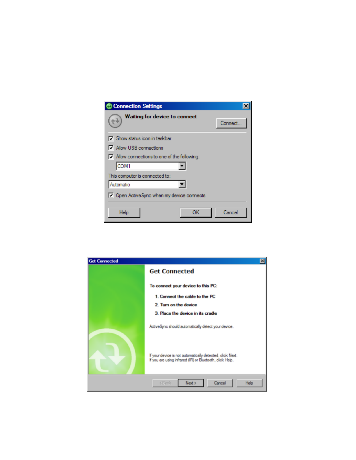
If nothing happens when you connect the cable, check to see if you have the ActiveSync icon in your system tray. If you
see this icon, right click on it and choose “Connection Settings”. You should see the following dialog:
Be sure that you have selected the appropriate COM port or USB options. Assuming that you are using a COM port
connection, you will choose the COM port (usually this will be COM1). Click Connect at the top right. You will now
see the Get Connected dialog.
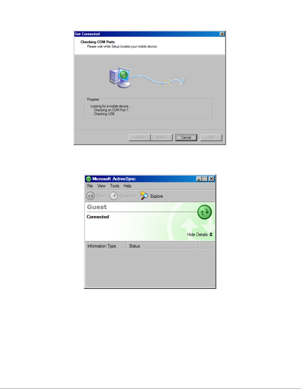
You now need to manually "link" to the remote device. Focus on the mobile device while still observing your PC screen.
Observe the above dialog and, with your device properly connected to the PC, be prepared to click the Next button at
the bottom. Now look at the mobile device screen for the "PC Link" icon.
First, click Next on the PC. Then immediately double-tap the PC Link icon. (You may have to do the double-tap more
p7
Page 10
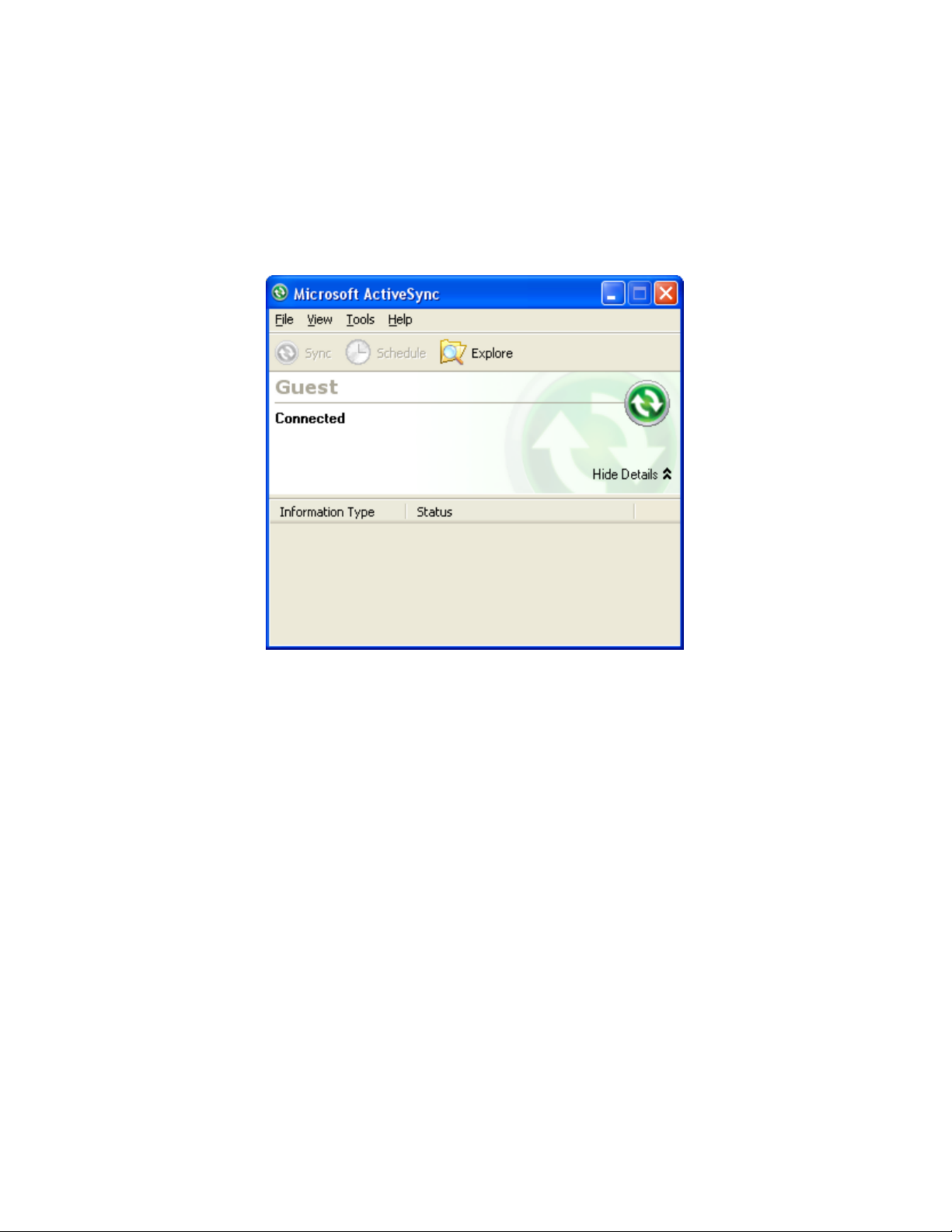
than once.) If successful, after you press Next, the following screen will appear and the connection will be made.
In ActiveSync, you will then see the New Partnership dialog. Click No to setting up a partnership, and click Next.
When you see the icon in the system tray, and it is green with no "x" through it, you are connected. Once you are
connected, you should see the following dialog. It should say "Connected":
Troubleshooting
If you cannot get connected, make sure that no other program is using the COM port. Programs to check for include any
Fax/Modem software and other data transfer software. If you see anything you think may be using the COM port, shut it
down and retry the connection with ActiveSync.
Enabling COM Port Communication for ActiveSync on Allegro, Panasonic Toughbook 01 and other CE devices
In order for ActiveSync to communicate, it may be necessary to direct the CE device to utilize the COM port as a
default. Some may come set default to USB. Go to Start (on Allegro, blue key and Start button), then Settings, and
open the Control Panel. Next choose the Communications icon, then PC Connection. Choose COM1 at a high baud
rate, such as 57,600 baud. This will download programs and files at a high rate of speed. On the Allegro, use PC Link
to connect to PC with ActiveSync. On the Panasonic Toughbook, do Start, Run, and in the Open window, type in
“autosync –go” (autosync then spacebar then “minus” go). Then go to Start, then Settings, and open the Control Panel.
Choose the Communications icon, then PC Connection. Change Connection to Serial Port @ 115K. Make sure “Enable
p8
Page 11
direct connections to the desktop computer” is checked.
Note:
When using FAST Survey’s Data Transfer option, you will need to disable Serial Port Connection (uncheck
Allow Serial Cable). This is done in the Connection Settings in ActiveSync. This option must be enabled again in order
to use ActiveSync.
Installing FAST Survey
Before you install FAST Survey, close all running applications on the mobile device.
Connect the mobile device to the desktop PC and ensure that the ActiveSync connection is made.
1.
Insert the CD into the CD-ROM drive on the desktop PC. If Autorun is enabled, the startup program begins. The
2.
startup program lets you choose the version of FAST Survey to install. To start the installation process without
using Autorun, choose Run from the Windows Start Menu. Enter the CD-ROM drive letter, and setup. For example,
enter d:\setup (where d is your CD-ROM drive letter).
On the desktop PC, a Welcome dialog will appear. Click Next.
3.
p9
Page 12
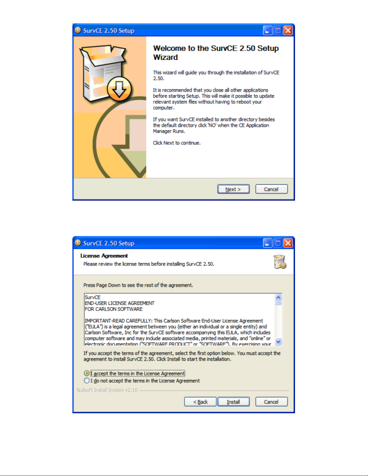
On the next dialog, you must read and accept the FAST Survey End-User License Agreement (EULA). If you agree
4.
with the EULA, click "I accept ..." and then select Install. If you do not agree with the EULA, click "I do not accept
..." and the installation program will quit.
The next dialog asks you to confirm the installation directory. Press Yes.
5.
p10
Page 13
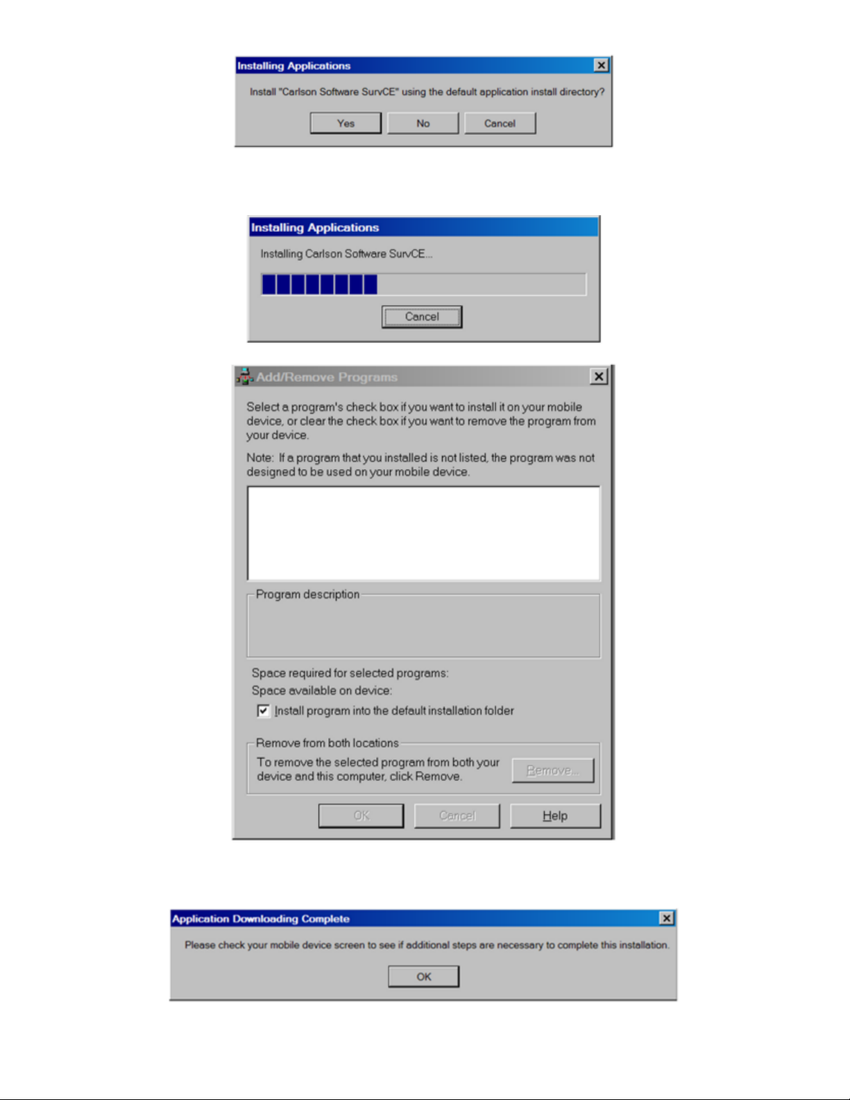
At this point, the necessary files will be copied to the mobile device. A dialog will appear to show installation
6.
progress.
You are given a final chance to check your mobile device. Click OK when you are ready, then click Finish on the
7.
desktop PC.
p11
Page 14
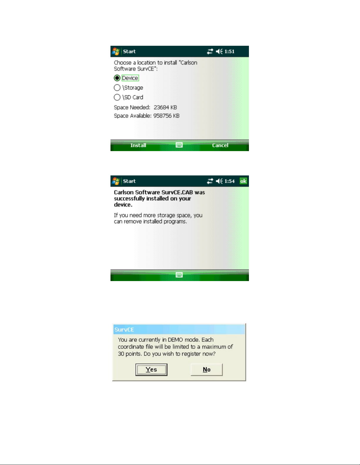
On the Data Collector - Tap “Install” in the bottom left to install FAST Survey to the default location of “Device”.
8.
After tapping Install you will see an hourglass with a progress bar showing the installation progress.
Once the Status Bar finishes on the data collector it will say “Software was successfully installed”. Tap OK in the
9.
upper right to complete the installation of FAST Survey.
Authorizing FAST Survey
The first time you start FAST Survey, you are prompted to register your license of the software. If you do not register,
FAST Survey will remain in demo mode, limiting each job file to a maximum of 30 points.
1) If you open FAST Survey and it says you are in “Demo Mode”, tap Yes to register now. If you are at the Main menu
of FAST Survey already you can tap the Equip tab / About FAST Survey and tap Change Registration to access this
screen.
2) Type in your FAST Survey Serial number into the Serial Number box at the top
3) Tap the “Get Code” button
p12
Page 15
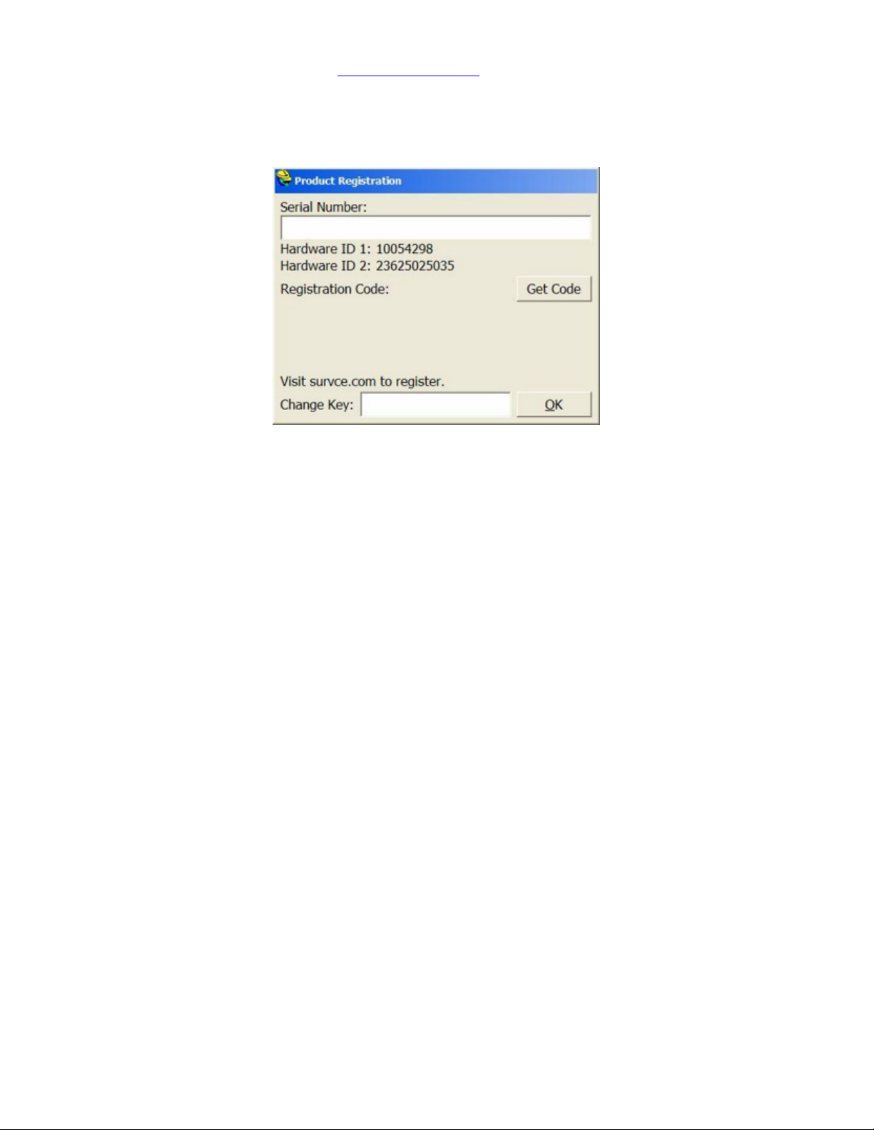
4) Now go to the FAST Survey website at www.survce.com/ashtech to complete your registration via the Internet
PLEASE NOTE: If you do not have access to the Internet, you may fax your company name, phone number, email
address, your FAST Survey serial number, Hardware #1, Hardware #2 and the registration code to 606-564-9525.
Your registration information will be faxed back to you within 48 hours.
5) Click on the “Registration Page” icon under Version 2.0/2.5
6) Fill out this form with your Name and Company information / type in your FAST Survey Serial number in the “Serial
Number” box and make sure to include the Dashes
7) Fill in the Hardware #1 and Hardware #2 boxes with the Values displayed on your Data Collector Screen {If you
have trouble finding them click the “where is it located link”}
8) Choose the Reason for Install of “Initial Installataion” if this is your First time registering FAST Survey
9) Fill in the Registration Code from the screen of your Data Collector and make sure to include the Dash
10) Click the Submit Registration Button
11) If this is your first time Registering FAST Survey you may need to fill in Some Contact Details then click “Submit
Contact Information”
12) If this is your first time Registering this Data Collector with FAST Survey please Select the “Device Model” from
the List and fill in the “Device Serial Number” and click the “Register Device to Complete Registration” button
13) Your Change Key will be displayed in a BOX in the Top Left of the FAST Survey Registration summary. Type this
change key in on the “Change Key” box on your Data Collector then tap OK
14) You should receive a message saying “Successful FAST Survey Registration!”. Tap OK
15) Your FAST Survey Software is now Fully Registered. Your change key will also be emailed to the address that you
submit. Keep a copy of this email for your permanent records.
Hardware Notes
If FAST Survey quits responding, you can reset the hardware by following the applicable procedures described in the
hardware documentation.
Color Screens
FAST Survey enables viewing of color. Any red, green, blue or other colored entities in DXF files will retain their color
when viewed within FAST Survey. Points will appear with black point numbers, green descriptions and blue elevations.
Dialogs and prompting will utilize color throughout FAST Survey.
p13
Page 16

Memory
Memory is NOT an issue with newer data collectors running Windows Mobile. Please ignore this section of you have a
Windows Mobile device. For all Windows Mobile users, there is no need to do any memory allocation. This section
applies only to older, Windows CE devices like the early Rangers and Allegros.
Memory on most Windows CE devices (excluding Windows Mobile), can be allocated directly by the user for best
results when running or installing FAST Survey. We recommend setting “Storage Memory” to a minimum of 16,000
KB. The following discussion is an example for setting that memory . An equivalent process should be used for other
CE devices, as available.
The FAST Survey controller will function better during topo and stakeout with the "Storage Memory" set to around
18,000 KB. Use the following process to check and/or change the settings:
Go to the start menu by simultaneously hitting the
double click on
side, so that
Keep in mind that to upgrade software, this setting may need to be changed back, so that the Program Memory has more
available. To change, do as above but slide the pointer toward the right, which is the Program side, so that
18,000 KB
around
Once the upgrade or additional software is added, you can change it back so that the pointer is more toward the Storage
Memory -- around 18,000 KB.
After changing these settings, or updating software, it's a good idea to do a "Save System".
System
. Touch the
Allocated
. This assures that there is enough Program memory, so that the new updates can be saved.
is around
Memory tab
18,000 KB
Blue Key
and slide the pointer toward the left, which is the Storage Memory
.
and
Start
. Choose
Settings,
Control Panel,
then
Allocated
then
is
Battery Status
Battery Status of Data Collector
status of the data collector itself. Full black should indicate full battery. As battery levels decrease the black recedes to
full white (out of battery).
Most Windows Mobile devices show an accurate battery status. If you tap the battery icon, it will display the exact
battery percent available, as in 73% (for example). On some CE devices, there is no way to detect battery status, so the
battery icon does not change. On other devices such as the Jett CE, a partial indication of battery status is detected as
follows:
: The black icon that appears at the top of every screen is designed to indicate battery
Good - 100%
Low - 50%
Critical – 10%
Save System
On older Windows CE devices, its highly recommended that you perform a Save System on the device after installing
FAST Survey or making any system level changes (eg. memory settings).
Examples:
Allegro
Start Programs Utilities Save System
This is not necessary (or even possible) on most Windows Mobile data controllers. Windows Mobile itself protects
against loss of registries and data when the power is low or disrupted.
p14
Page 17
User Interface
This chapter describes the general user interface features of FAST Survey.
Graphic Mode
Icons
FAST Survey can be configured to show either the traditional letter icons or graphical icons for several functions. To set
this option, go to the EQUIP tab, select Configure and toggle the "Use Graphic Icons" check box.
(ALT-A).
taken by laser and hydrographic devices that measure distance only, or distance and azimuth (ALT-O).
preferences in FAST Survey such as the number of readings to average, function of the Store icon, and whether to
This icon will Read a measurement (ALT-R).
Total Station Only. This icon will Traverse to the measured point by advancing your setup (ALT-T).
This icon will Store a point. This function is also performed via the Enter key. (ALT-S).
This icon will lead to a dialog where the user can
This icon leads to
This icon will take you to the
O
ffset reading screens with options for keyed-in offsets as well as offsets
C
onfigure dialog, also found on the EQUIP tab. Here you set many
p15
A
verage up to 999 epochs of GPS readings
Page 18
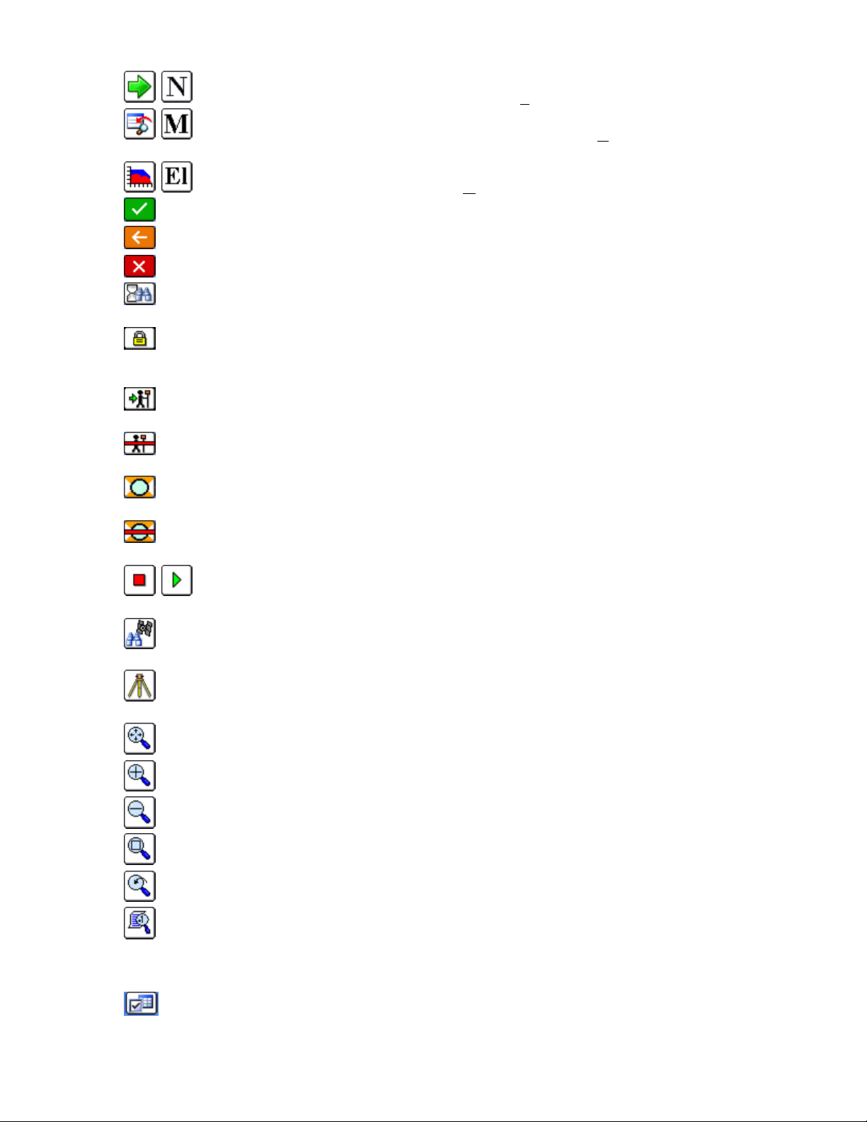
display the Hgt/Desc prompt on Save (ALT-C).
stake data.
the instrument in search mode when then leads to lock mode when the prism is found.
the robotic total station in Standby mode, meaning it will suspend tracking mode (e.g. allows you to place the pole
down, drive a stake, then resume work).
(tracking) and when pressed will stop the EDM.
distances (not tracking) and when pressed will start the EDM.
will switch the instrument to reflectorless mode.
This icon will advance stake location incrementally to the
This icon returns to the previous stakeout settings dialog where you can
This icon allows the user to override the design
OK:
This icon will accept the dialog.
Back:
This icon will return you to the previous dialog.
Exit:
This icon will return you to the main menu and dismiss any changes (ALT-X).
Standby/Search:
Locked:
Tracking is On:
Tracking is Off:
Prism Mode:
Robotics only. This icon shows that the instrument is locked on the prism, and when pressed, places
Robotics only. This status icon shows the instrument is in standby and when pressed, puts
Robotics only. This icon shows that the instrument is continuously measuring distances
Robotics only. This icon shows that the instrument is NOT continuously measuring
This icon shows that the instrument is currently configured to read a prism and when pressed
El
evation (ALT-E).
N
ext point or station (ALT-N).
M
odify the current design
Reflectorless Mode:
will switch the instrument to prism mode.
Stop/Go:
(ALT-G).
Monitor/SkyPlot:
Lat/Long display (ALT-D).
Tripod:
and Remote Benchmark (ALT B).
Zoom Extents:
Zoom In:
Zoom Out:
Zoom Window:
Zoom Previous:
View Options:
symbol, the style of the plot and the freezing or thawing of attributes such as descriptions and elevations. To avoid
“point clutter”, you can even set it to show only the last stored point along with setup and BS. See the View Options
section of this manual.
This will take you to the Instrument Setup dialog. This dialog contains Backsight, Setup, Robotics
Zooms in 25%.
Zooms out 25%
This icon shows that the instrument is currently in reflectorless mode and when pressed
This icon, inside of Auto By Interval, begins and pauses the action of recording points
This icon will take you to the Monitor/SkyPlot screen for GPS status and Coordinate and
This zooms the entire drawing to fit the screen.
Zooms into a rectangular area that you pick on the map screen.
Zooms to the previous view. FAST Survey remembers up to 50 views.
Displays the View Options dialog box, where you can control aspects of points such as the
Pan
Settings
: This icon leads to settings associated with the current command or option.
p16
Page 19
You can also pan the screen simply by touching it, then holding and dragging your finger or stylus along the screen
surface. Pan is automatic and needs no prior command.
View/Edit Points by Touch
You can edit or delete any point by simply clicking on it graphically. In the Store Points command, clicking on a point
also allows you to Re-Measure the point location, both in GPS and Total Station mode.
Text Mode
The Text screen uses a large character size for easy viewing, and limits options to Monitor/Skyplot, Offset and Store.
Select the Text mode by clicking on the Helmet in the upper left of the screen, in most active survey commands,
choosing Text. You can return to the Graph view by tapping the Helmet icon and choosing Graph. You can also
temporarily view your points on the screen by tapping
screen. Note that the program will remember which screen you were in last (Graph or Text) and return to that mode of
data collection automatically.
Map
, then tap
Back
to return to the text-based data collection
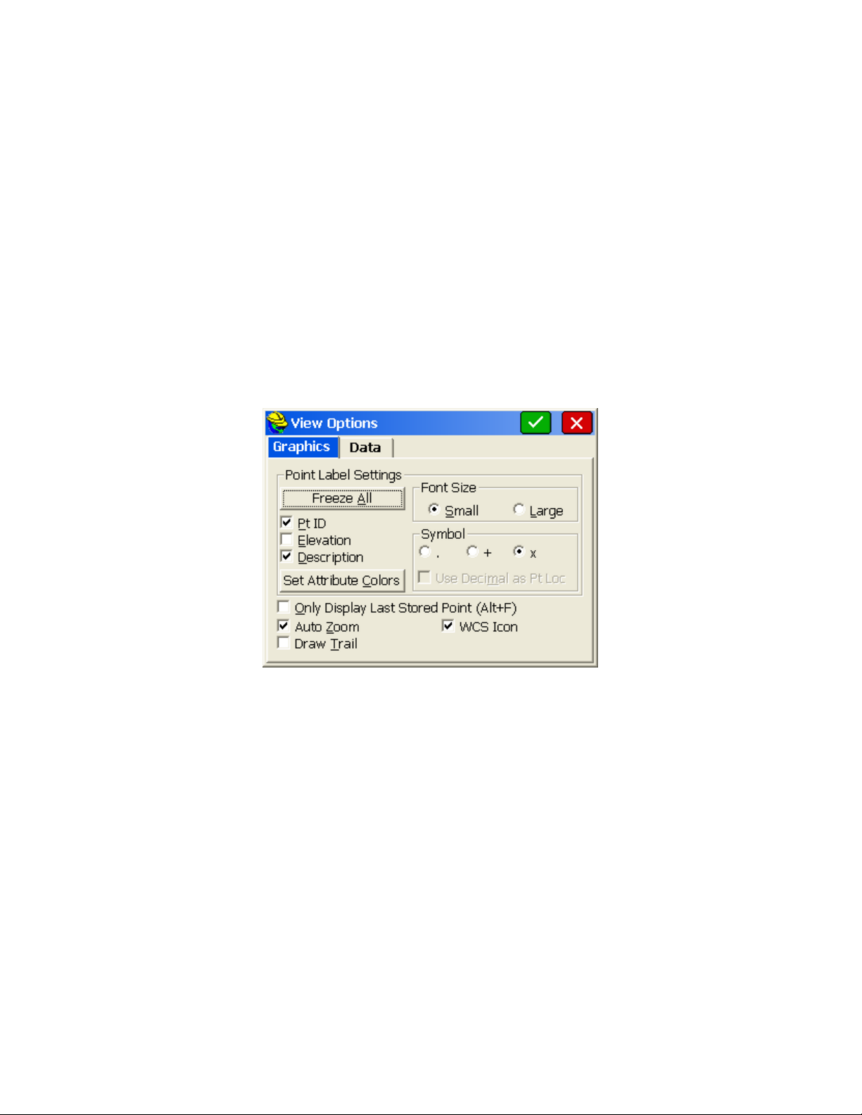
View Options
The graphic view has all of the standard zoom icons as well as a View Setting Icon in the lower left. This icon allows
you to change the way the graphical items will be displayed. The View Setting Icon will show more options such as the
"Alt-F" (store last point only) option when clicked during commands such as Store Points and Stake Points (active
survey commands).
Freeze All:
Each attribute can be toggled off separately as well.
Font Size
Use Decimal as Point Location:
point of the elevation. It applies if the "dot" symbol is used.
Set Attribute Colors:
Only Display Last Stored Point (ALT-F):
collected, the instrument and backsight points, and the last point collected. This is a popular setting to reduce the
clutter of numerous points displayed all at once.
Auto Zoom
magnification, and in stakeout commands, the zoom includes your target and current location. If turned off, the
program holds the current window.
Draw Trail
direction of movement is shown by an added trail or tail associated with the arrowhead (current position).
WCS Icon
The Data tab goes to a secondary screen which normally shows only the Intelligent Zoom option, but when selected
from the Map screen (globe icon), also includes Traverse Defaults:
This toggle will freeze (hide from view) the point attributes (e.g. Point ID, Elevation and Description).
: Points can be small (default setting) or large and bold for easier readability.
This toggle will adjust the text location so that the point location is the decimal
This button will allow users to specify the colors of the point text (color units only).
This toggle will result in FAST Survey only displaying the linework
: Normally clicked on, this setting zooms to your location in survey commands at the current zoom
: For GPS and robotic total station work where the current position is updated continuously, the
: This shows the N/E icon on the graphic screen, for orientation.
p17
Page 20
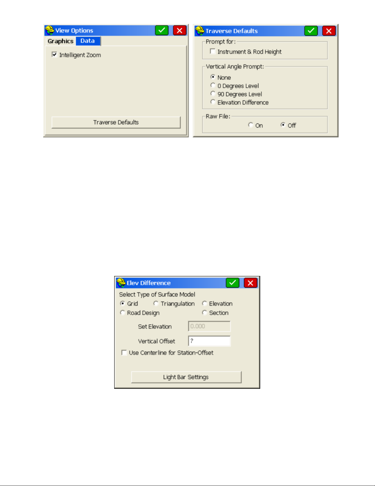
Intelligent Zoom
"Intelligent Zoom" allows you to pick the point from the screen in a condensed area of points, and the program will
auto-zoom allowing you to pick again and obtain the precise point that you want. If Intelligent Zoom is off, you
would instead see a list of points and must pick from the list or return to the Map screen and zoom in closer using
the Zoom + or Zoom Window options.
Traverse Defaults
instrument height, rod height and zenith angles as set in this dialog, and will optionally store to the raw file for
processing. This allows for very fast manual entry of raw field data.
: When selecting points "From Map" in commands such as Inverse or Stake Points, the
: The T for Traverse and S for Sideshot commands, within the Map screen, will prompt for
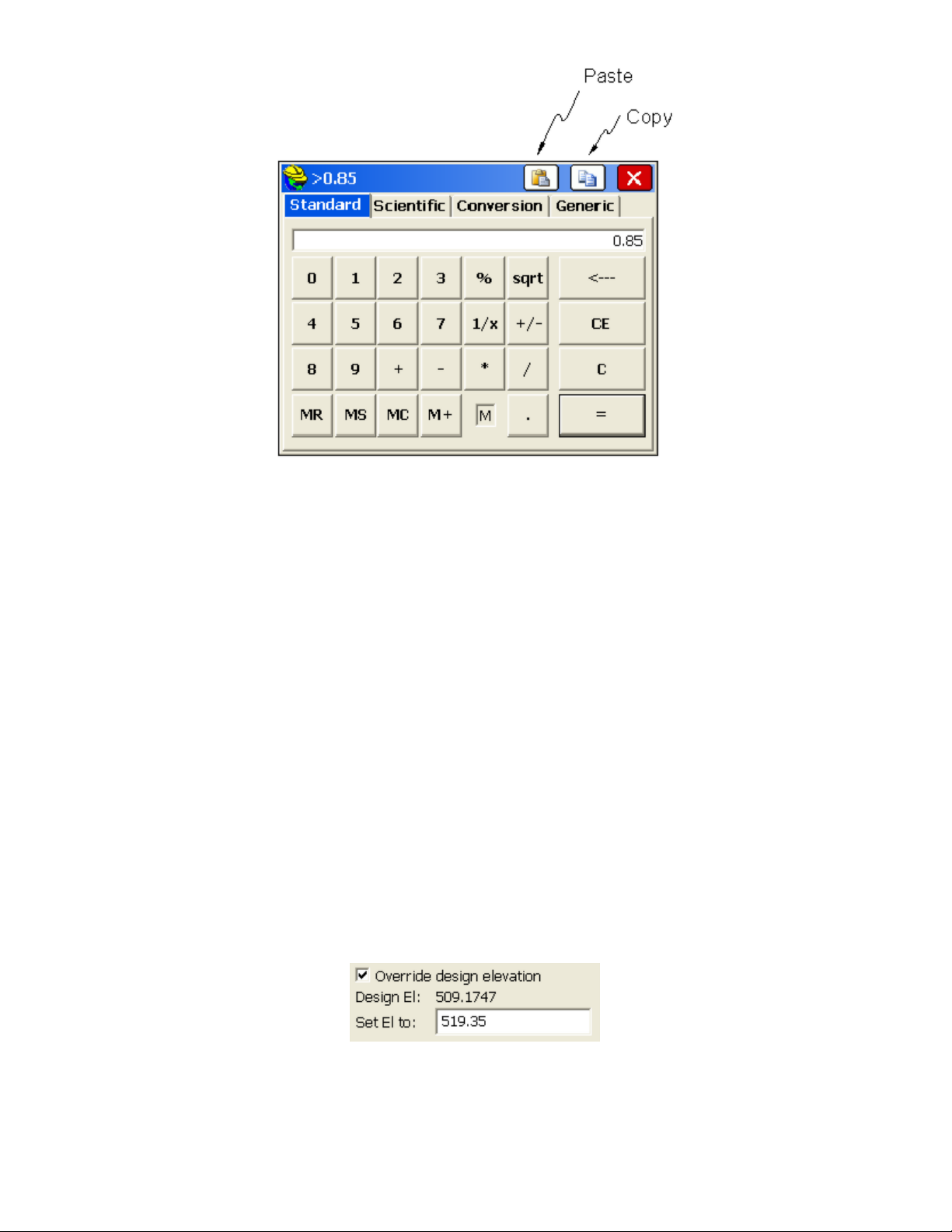
Quick Calculator
From virtually any dialog entry line in the program, the ? command will go to the Calculator routines and allow copying
and pasting of any selected calculation result back into the dialog entry line.
For example, if you were grading a site that had 4 subgrades, and had modeled the top surface, you need to grade to the
lowest subgrade surface with a vertical offset of (0.12+0.15+0.33+0.25). You could quickly obtain the value by
entering ? in the Vertical Offset field within the
Elevation Difference
dialog, as shown in this next figure.
This leads immediately to the
Standard tab, we can enter 0.12+0.15+0.33+0.25 and then "=" . Then select the
the banner line at the very top of the screen. Then choose
edit box. Change the sign to "-" for negative, as needed. Calculations can also be done directly from the edit box
within the
units setting. In this same edit box, you could also enter 19.5/12, which would do the division directly in the edit box.
Vertical Offset
Calculator
dialog. You could enter "19.5 in" for inches, which would auto-convert to feet or the current
dialog, with its four tabs, or options, many with sub-options. Using the
Copy
button, which places the value in
Paste
to paste the value back into the
p18
Vertical Offset
dialog
Page 21
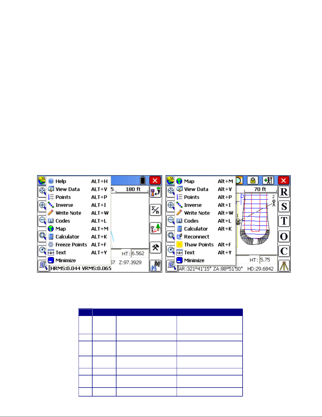
Hot Keys & Hot List
The ALT key commands take the form ALT-C (Configure Reading) or ALT-N (Next Point). The ALT key and the
subsequent "Hot Key" (“C” or “N”, as mentioned here) can be entered at nearly the same time or with any delay desired.
If you press ALT and delay the entry of the hot key, you will see a text instruction: “Waiting for HotKey… Press Alt
again to return”. A second ALT returns to the previous position in the program without executing any command. ALT< and ALT- > will brighten or darken screens on “At Work” brand CE data collectors.
List of Hot Key Commands Activated by ALT
Many of the hot keys work only within related data gathering commands, as opposed to working from the main menus.
Hot Keys vary by command. For example, in the Store Points screen, the hot keys are as follows.
ALT-R
ALT-S
ALT-O
ALT-C
ALT-B
Here is a list of other common hot keys:
ALT-E
Elevation Difference and virtually all stakeout commands except Stakeout Points, ALT-E will allow the user to
enter an alternate design elevation different from the computed current design elevation. The screen prompt
appears below:
ALT-F
all but the setup point number, backsight point number and current foresight shot. This is helpful when points are
densely located. Alt F again returns to the full point plot. Linework remains. In GPS Mode, Alt-F hides (freezes)
all points, but shows a solid square symbol for the last GPS-measured point.
ALT-H:
: Read (Total Station Only)
: Store (or Shot/Store)
: Offset
:Configure Reading
: Backsight (Total Station Only)
: Target Elevation — From the stakeout screen in any Stakeout Line/Arc command, Offset Stakeout,
: Foresight Only Toggle. When in the Store Points graphic screen and taking new shots, ALT-F will freeze
Help. Takes you to the Help menu, where available.
p19
Page 22
ALT-I
Key
GPS
Conventional TS
Robotic TS
A
Take
Average
Reading
Read and Store (All)
Read and Store (All)
B
Total Station Setup
Setup and Robotics
C
Configure
Reading
Configure Reading
Configure Reading, Sets,
Settings and Search
D
Monitor
GPS
Manual Read
Leica: Toggle EDM; Others:
Manual Read
E
F
Freeze
Points
Freeze Points
Freeze Points
G
Start/Stop
Start/Stop Interval Recording
In most measurement screens you can also select the FAST Survey Helmet icon at the top left to access the hot list of
shortcuts to other routines. Depending on what commands you are in, or if a Bluetooth devices is involved (Reconnect
option), the Helmet options appear as shown:
: Inverse. Does a quick inverse, and upon exit, returns you to the command you were in. Inverse is also
accessible from the Helmet in the upper left of the screen, in many commands including Store Points.
ALT-J
: Joystick. Applies only to robotic total station. Takes you to the Settings option. ALT-J typically only
functions if you are configured for a robotic total station. ALT-J will work from within data gathering commands,
most stakeout commands (eg. Stake Points) and from the main menus.
ALT-L
: List, as in Feature Code List. When entered in any Description field, this will recall the Feature Code List,
which displays the characteristics (layer/linework) of the feature code. This serves not only as a way to select the
code and apply it to the description, but it also serves as a handy reminder of the code’s properties. Helmet-Codes
also goes to the Feature Code List.
ALT-M
ALT-N
ALT-T
presented for verification. Applies when in the Store Points routine.
ALT-V
ALT-W
ALT-X
?
SDR8100 is an exception. This device uses the ‘=’ symbol.)
: Map Screen. ALT-M will switch to the map screen.
: Next. Moves you to the Next point or station in the Stakeout commands.
: Traverse. Takes a reading and advances the setup to the measured point. The instrument setup dialog is
: Shortcut to View the Raw Data, Point Data, Feature Codes and Cutsheets.
: Write a Note anytime with this command. Notes store to the Raw File.
: Shortcut to Exit most commands. Similar to Esc (escape key).
: The ‘?’ character can be used in any field that requires a numerical entry to access the Calculator. (The Sokkia
While in any Topo (Store Points) or Stakeout routine, a number of features are accessible by pressing ALT, followed by
the corresponding Hot Key. Below is a list of Hot Keys arranged by routine and equipment type.
Action in Topo Mode Summary
p20
Page 23

Interval
Recording
H
Help
Help
Help
I
Inverse
Inverse
Inverse
J
Sokkia Motorized: Joystick
Joystick
K
Calculator
Calculator
Calculator
L
Feature
Code List
Feature Code List
Feature Code List
M
View Map
View Map
View Map
N
O
Offset
Point
Collection
Offset Point Collection
Offset Point Collection
P
List Points
List Points
List Points
Q
Toggle
Prompt for
Hgt/Desc
Toggle Prompt for Hgt/Desc
On and Off
Toggle Prompt for Hgt/Desc
On and Off
R
Read
Read and Store
S
Store
Store
Store
T
Traverse
Traverse
U
V
View Raw
File
View Raw File
View Raw File
W
Write Job
Notes
Write Job Notes
Write Job Notes
X
Exit to
Main
Menu
Exit to Main Menu
Exit to Main Menu
Y
Toggle
Graphics/T
ext Mode
Toggle Graphics/Text Mode
(Helmet-Graph to return)
Toggle Graphics/Text Mode
(Helmet-Graph to return)
Z
Zoom to
Point
Zoom to Point
Zoom to Point
Action in Stakeout Mode Summary
Key
GPS
Conventional TS
Robotic TS
A
B
Total Station Setup
Total Station Setup
C
Configure Reading
Configure Reading
Configure Reading
D
Monitor GPS
Leica: Toggle EDM
E
Set Target
Elevation
Set Target Elevation
Set Target Elevation
F
Freeze Points
Freeze Points
Freeze Points
G
H
Help
Help
Help
I
Inverse
Inverse
Inverse
J
Sokkia Motorized:
Joystick
Joystick
K
Calculator
Calculator
Calculator
L
Feature Code List
Feature Code List
Feature Code List
M
View Map
View Map
View Map
N
Next Point/Station
to Stake
Next Point/Station to
Stake
Next Point/Station to Stake
O
p21
Page 24
P
List Points
List Points
List Points
Q
R
Read
Read and Store
S
Store
Store
Store
T
U
V
View Raw File
View Raw File
View Raw File
W
Write Job Notes
Write Job Notes
Write Job Notes
X
Exit to Main Menu
Exit to Main Menu
Exit to Main Menu
Y
Toggle
Graphics/Text
Mode
Toggle Graphics/Text
Mode (Helmet-Graph to
return)
Toggle Graphics/Text
Mode (Helmet-Graph to
return)
Z
Zoom to Point
Zoom to Point
Zoom to Point
Instrument Selection
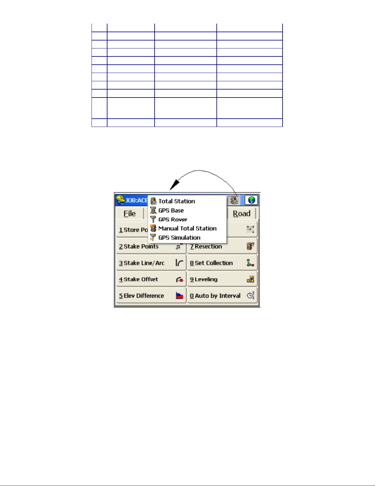
The user can switch between current instruments using the Instrument Selection flyout on the top bar of FAST Survey.
Input Box Controls
When point IDs are used to determine a value, the program will search for the point IDs in the current job. If not found
it will then search in the control job, if active.
Formatted Distance/Height Entries
Entries for distances or heights that include certain special or commonly understood measurement extensions are
automatically interpreted as a unit of measurement and converted to the working units as chosen in job setup. For
example, a target height entry of 2m is converted to 6.5617 feet if units are configured for feet. The extension can
appear after the number, separated by a space (2 m), or can be directly appended to the number (2m). For feet and inch
conversion, the second decimal point informs the software that the user is entering fractions (See Below). Recognized
text and their corresponding units are shown below:
f or ft:
US Feet
i or ift:
International Feet
in:
Inches
cm:
Centimeters
m:
Meters
#.##.#:
Feet and Inches (e.g. 1.5.3.8 = 1'5 3/8" either entry format is supported)
p22
Page 25

These extensions are automatically recognized for target heights and instrument heights, and within certain distance
entry dialogs. Entries are not case sensitive.
Formatted Bearing/Azimuth Entries
Most directional commands within FAST Survey allow for the entry of both azimuths and bearings. Azimuth entries are
in the form 350.2531 (DDD.MMSS), representing 350 degrees, 25 minutes and 31 seconds. But that same direction
could be entered as N9.3429W or alternately as NW9.3429. FAST Survey will accept both formats. Additional
directional entry options, which might apply to commands such as Intersection under Cogo, are outlined below:
If options in Job Settings are set to Bearing and Degrees (360 circle), the user can enter the quadrant number before the
angle value.
Example
120.1234
The result is N20°12’34’’E.
Quadrants
1 NE
2 SE
3 SW
4 NW
In the case where Job Settings have been set for Bearing, and the user would like to enter an Azimuth, the letter A can
be placed before the azimuth value and the program will convert it to a Bearing.
Example
A20.1234
The result is N20°12’34’’E.
In the case where Job Settings is set to Azimuth and the user would like to enter a bearing, the quadrant letters can be
used before the bearing value.
Example
NW45.0000
The result is 315°00’00”.
Formatted Angle Entries
Interior Angle:
The user can compute an angle defined by three points by entering the point IDs as <Point ID>,<Point
ID>,Point ID>. The program will return the interior angle created by the three points using the AT-FROM-TO logic.
Such entries might apply to the Angle Right input box in Store Points when configured to Manual Total Station.
Example
1,2,3
Using the coordinates below, the result is 90°00’00”. Point 2 would be the vertex point.
Pt. North East
1 5500 5000
2 5000 5000
3 5000 5500
Mathematical Expressions
Mathematical expressions can be used in nearly all angle and distance edit boxes. For example, within the Intersection
routine, an azimuth can be entered in the form 255.35-90, which means 255 degrees, 35 minutes minus 90 degrees.
Additionally, point-defined distances and directions can be entered with a comma as separator, as in 4,5. If point 4 to
point 5 has an azimuth of 255 degrees, 35 minutes, then the same expression above could be entered as 4,5-90. For
math, the program handles “/”, “*”, “-“ and “+”. To go half the distance from 103 to 10, enter 103,10/2.
Point Ranges
p23
Page 26

When ranges of points are involved, such as in stakeout lists, a dash is used. You can enter ranges in reverse (e.g..
75-50), which would create a list of points from 75 down to 50 in reverse order. For example, in Stake Points, you
could enter 75-50 for the point to stake, click "Add to List", then starting at point 75, stake 74, then 73, etc. by clicking
N for Next.
Survey Data Display Controls
ANGLE
The angle control will display the angle as defined by the current settings in Job Settings.
Options are available for Azimuth (North or South) or Bearing combined with the option of Degrees or Grads.
Format
The display format of degrees uses the degree, minute, and second symbols. For the case of a bearing we display the
quadrant using the characters N, S, W, E.
Example Bearing
N7°09'59"E
Example Azimuth
7°09'59"
All angular values entered by the user should be in the DD.MMSS format.
Example
7.0959
The result is 7°09'59".
Formulas
Formulas can be entered for working with angles. The format must have the operator after the angle value.
Example
90.0000 * 0.5
The result would be 45°00’00”
DISTANCE
The distance control will display the value using the current Job Settings unit. You can enter a formula using the
mathematical operators as described above.
Inverse
You can compute a distance from a point-to-point inverse by entering <Point ID>,<Point ID>.
Example
1,2
Using the coordinates listed below, the result is 500’.
Pt. North East
1 5500 5000
2 5000 5000
STATION
The station control will display the value using the current Job Settings format.
The same options described above for distance input boxes apply.
SLOPE
The slope control will display the value using the current Job Settings format.
Keyboard Operation
FAST Survey allows the user to operate the interface entirely from keyboard navigation, as well as touch screen
navigation. The rules for keyboard navigation are outlined below:
Controls
Button (Radio Buttons, Check Boxes and Standard Buttons)
Enter:
o
Right/Left Arrows:
o
Select the button.
Move to the next tab stop.
p24
Page 27

Right
Left
Up/Down Arrows:
o
Down
Up
Tab:
o
In Menus like Job Settings, Tab Right and Tab Left move through the tab headings (New Job, System, Format, Options,
Stake) along the top of the dialog, while the right and left arrows move up and down through the options within each
tab.
Drop List
o
o
o
o
Edit Box
o
o
o
o
Tab
o
o
o
o
Move to the next tab stop.
Enter:
Right/Left Arrows:
Up/Down Arrows:
Tab:
Enter:
take a reading. For all other edit boxes, ENTER moves through the tab stops.
Right/Left Arrows:
Up/Down Arrows:
Tab:
Enter:
Right/Left Arrows:
Up/Down Arrows:
Tab:
Selects the highlighted option within each drop list.
Right
Left
Move to the next tab stop.
Move to the next tab stop. For any measurement screen, if focus is in the description edit box,
Down
Up
Move to the next tab stop.
Move to the next tab stop.
Right
Left
Down
Up
Move to the next tab stop.
[Tab]
[Shift+Tab]
Move to the next tab stop.
[Tab]
[Shift+Tab]
Move to the next tab stop.
[Tab]
[Shift+Tab]
Move through the list items.
Move through the text like standard windows.
Move to the next tab stop.
[Tab]
[Shift+Tab]
Move through the tabs.
Next Tab
Previous Tab
Move to the next tab stop.
[Tab]
[Shift+Tab]
Abbreviations
Adr: Address
AR: Angle Right
Avg: Average
Az: Azimuth
Bk: Back
Calc: Calculate
Char: Character
Chk: Check
cm: Centimeter
Coord(s): Coordinate(s)
Ctrl: Control
Desc: Description
Dev: Deviation
p25
Page 28

Diff: Difference
Dist: Distance
El: Elevation
Fst: Fast
ft: Foot
Fwd: Forward
HD: Horizontal Distance
HI: Height of Instrument.
Horiz: Horizontal
Ht: Height or Height of Antenna with GPS.
HT: Height of Target.
ID: Identifier
ift: International Foot
in: Inch
Inst: Instrument
Int: Interval
L: Left
m: Meter
No: Number
OS: Offset
Prev: Previous
Pt: Point ID
Pts: Points
R: Right
Rdg: Reading
SD: Slope Distance
Sta: Station
Std: Standard
Vert: Vertical
ZE: Zenith
p26
Page 29
FILE
This chapter provides information on using the commands from the File menu.
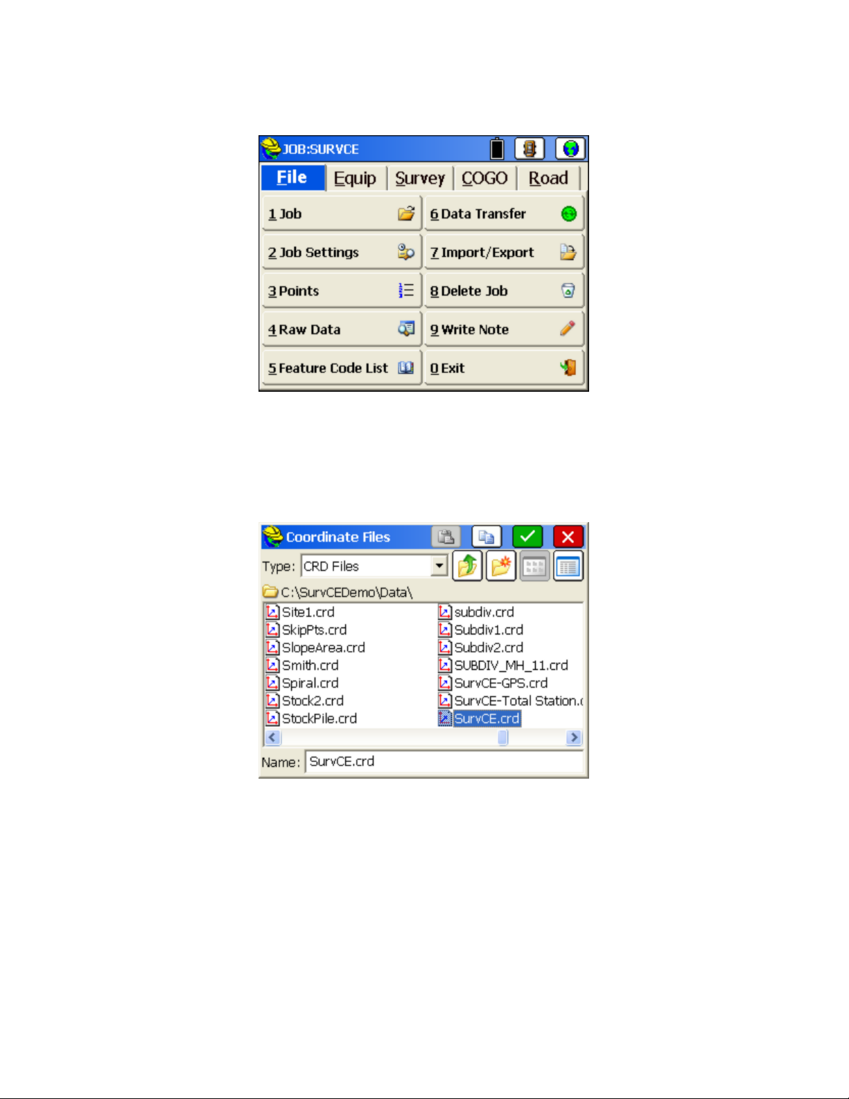
Job
This command allows you to select an existing coordinate file for your job or to create a new coordinate file. The
standard file selection dialog box appears for choosing a coordinate file, as shown in the next figure. Buttons for moving
up the directory structure, creating a new folder, listing file names and listing file details appear in the upper right corner
of the dialog box.
All data points you collect are stored in the coordinate (.crd) file you select or create. The .crd file extension will
automatically be appended to the file name.
Select Existing Job
To select an existing job, browse to and select an existing file, then select OK (the green check icon).
Create a New Job
To create a new job, simply enter a new name and select OK. You can control where your job is saved by browsing to
the desired folder where the job is to be created before entering the new name and selecting OK. You can also create a
new folder for this new file name. Following job creation, you will be asked to enter in Job Attribute information. This
feature lets you set up prompting for each new job with job-related attributes like Client, Jurisdiction, Weather
Conditions and the like. The information is stored in the raw file. This is discussed in detail in the Job Setting section.
Copy and Paste Job
The Copy icon at the top of the dialog let's you copy an existing file and then paste it with the Paste icon into a different
p27
Page 30
directory, as selected.
Note:
If you key in a coordinate file that already exists, it will load the file instead of overwriting it with a new file. The
benefit of this feature is that you cannot accidentally overwrite an existing coordinate file from within FAST Survey.
Job Settings (New Job)
This tab allows you to configure how all new jobs will be created.
Prompt for First Pt
when starting a new job. If enabled, you specify the default starting point coordinates in the left column. This
applies for total station use only.
Prompt for Units
start a new job.
Use Last Job Localization:
project scale. If this feature is disabled, each new job will start out with no localization and a project scale of 1.0.
The default value is off.
Attach Last Control Data:
the control file will automatically be deactivated during new job creation.
Cutsheets:
your job was named Macon1.crd, then the 3 cutsheet files created would be Macon1-Pt.txt (for non-alignment,
point-only stakeout), Macon1-CL.txt (for stakeout involving alignments) and Macon1-Sl.txt (for slope staking).
Recall Previous will allow the user to use the same cutsheets on all new jobs. With Manual, the control file will
automatically be deactivated during new job creation and you will need to create cutsheet files within the Stake tab
of Job Settings. Cutsheets normally store in ASCII (*.txt) format but can store in EXCEL (*.csv) format if selected
within Job Settings, Options.
Use Template DXF:
will be used and displayed in the field. The feature works well with use of Feature Codes for linework. If you
designate code 201, for example, as a pavement edge in the layer BitPav, you could make a blank DXF drawing
with BitPav layer created, set to color blue. Then using that "template dxf" file, everytime you code a 201, you will
see the blue linework as an extra confirmation of correct coding. This color-coding could be repeated for other
often used layers.
Define Job Attributes:
Jurisdiction, Weather Conditions, Party Chief and other notes. These will prompt when each new job is started, and
the attributes and entries will appear in the raw file (.rw5) file. Select Add to enter new attributes.
Auto-Save by job will automatically create cutsheet files (in the last format used) for each new job. If
: This option specifies whether or not FAST Survey will prompt you to specify a starting point
: This option specifies whether or not FAST Survey will prompt you to set the units when you
If this feature is enabled, each new job will use the previous job’s localization file and
This allows the user to use the same control file on all new jobs. With this option off,
This allows users to create an empty DXF file that contains all of the layers and colors that
This lets you set up prompting, for each new job, for job-related attributes like Client,
p28
Page 31

Job Settings (System)
This tab allows you to define the units for the current job.
Distance
or International Feet is selected, you have the option to display distances as decimal feet (Dec Ft) or Feet and
Inches (Inches). This is a display property only and will not change the format of the data recorded to the raw file.
Angle
(also refered to as grads- 400 circle and fully decimal). An angle of 397.9809 gons is equivalent to 358 degrees, 10
minutes and 58 seconds. (Note: you can verify this in Cogo, Calculator, Conversion tab). The Angle Unit
configuration impacts commands such as Inverse, Traverse, Sideshot, Input-Edit Centerline and other commands
where a direction is displayed or entered.
Zero Azimuth Setting
Edit Projection List
This is done by selecting projectcions from Predefined choices, per the menu option below. Predefined choices
include NAD 27 and NAD 83 for the United States and UTM for projections around the globe, as well as individual
country projections. You can also Add User Defined projection systems, where you enter the New System name,
choose the Projection type for an extensive list, then enter all the information requested such as False Northing,
False Easting, and the items within "New Datum".
: Select the units that you want to use. Choices include US Feet, International Feet, and Metric. If US Feet
: This offers the option of degrees (360 circle, 60 minutes to a degree and 60 seconds to a minute) or gons
: Allows you to specify the direction for zero azimuth, North or South.
: You can create a short list of commonly used projections that appear in the pulldown list.
p29
Page 32

Note:
The Projection selection applies primarily to GPS work and your localization file. It enables automatic
calculation of grid to ground and ground to grid factors, for example (See Localization). However, the Projection can
also apply to total station work. When you do any processing of your data within the Raw Data option (File Menu),
there is an option "Reduce to Grid Coordinates". If this option is turned on, then the position on the projection is
calculated for each point in the traverse and for each sideshot, and leads to a specific grid factor. The grid factor,
combined with the elevation factor, leads to computation of the combined factor, which is applied to each traverse and
sideshot. The program then calculates the fieldwork at sea level on the projection (ground to grid). This can improve
your closures especially when traversing from one known grid system monument to another. Selecting and applying the
correct projection is also useful when trying to match total station measurements (often located on the ground) to
GPS-based survey work (typically located on the grid, at sea level).
Job Settings (Format)
This tab allows you to select the viewing format of the data displayed and entered in the current job.
Coordinate Display Order:
East then North.
Angle Entry and Display
prompting and displays in Sideshot Traverse (the backsight as azimuth or bearing), Intersections, and Inverse.
Vertical Observation Display
Vertical Angle (90 degrees up, 0 degrees level) or Elevation Difference (up is positive in absolute units, down is
negative). Normally combine Elevation Difference with Horizontal Distance. If combined with Slope Distance, the
non-zero Elevation Difference will be used to compute the equivalent zenith angle and will reduce the Slope
Distance to a lesser Horizontal Distance. (Applies to entries in Manual Total Station mode).
This option allows you to display coordinates with the order of North then East or
: Options are Bearing or Azimuth. This applies to numerous commands, such as
: Allows you to set the default prompting to Zenith (0 degrees up, 90 degrees level),
p30
Page 33

Distance Observation Display
station readings.
Slope Entry and Display
Percent, Degrees or Ratio; however, some commands such as 3D Inverse will automatically report both slope and
ratio and are unaffected.
Station Display
the U.S., for example, roads designed in feet are “stationed” by every 100 feet, so that a road at linear position
14280.5 is given a station of 142+80.50. Metric roads in the U.S. are often stationed by kilometers, where the same
road position has a station of 14+280.500. You can configure the placement of the “+” as desired, independent of
your configuration for metric vs feet units. You can also configure for a purely decimal display of
stationing/chainage, as in 14280.500. This display form shows up in such commands as Input-Edit Centerline,
within the Start Station dialog box. Please note that you should still input the stationing in purely numeric form,
without the “+” convention. Only the display is impacted by this option.
: This option impacts the display of centerline stationing, sometimes referred to as “chainage”. In
: Options are Slope or Horizontal. This applies to the values displayed from total
: Whenever slopes are reported or prompted, you have the option to specify the default in
Job Settings (Options)
This tab allows you to set configuration options for the current job.
Time Stamp Each Point
Raw files in FAST Survey have a .RW5 extension and are nearly identical to the TDS .RW5 format. See the image
below for simple FAST Survey .RW5 file.
Store GPS Accuracy in Raw File
the horizontal and vertical quality as reported by the GPS will be stored to the raw file with each point (RMS or
CEP/SEP typically).
: When enabled, a date and time stamp will be noted in the raw file beside each point.
: This option is available when configured to any GPS equipment. If enabled,
p31
Page 34

Use Code Table for Descriptions
draw symbols and linework within specific layers. Special code icons also appear when "Hgt/Desc Prompt on
Save" is on (within Equip-Configure). If "Use Code Table" is clicked off, use of feature codes is disabled and no
linework or symbol drawing will occur. When clicked off, only the current descriptions used in the current job will
appear. Most users will turn on the "Use Code Table" option and access the power of the feature codes. Only users
who do not want linework and symbols and only wish to see the specific descriptions in their current, active job will
benefit from turning off "Use Code Table". When clicked off, only the current descriptions used in the active job
appear for re-use by picking.
: This feature activates feature code usage. If on, feature codes can be used to
Recall Job Road Files
in the non-roading version of FAST Survey. When enabled, this option will recall the last roading files (centerlines,
profiles, templates, superelevation files, etc.) used in road stakeout. Routines in the Road menu such as Stake Road
and Slope Staking will automatically recall the last-used roading files
Recall Job Localization
for several days. It allows you to set up the base in the same location, change only the base antenna height in
Configure Base (if applicable), then continue to work. You must have at least 1 point in the file (which initiates the
RW5, “raw”, file) for the GPS localization to be auto-recalled. With this option disabled, you would have to go to
Localization within the Equip menu and Load the stored localization (.dat) file. Even with the option turned on,
you can always move to a new job and create or load another localization file. The localization file (*.dat file) is
recalled as long as there is at least one coordinate point in the job.
Auto Load Map and Auto Save Map
These maps can be created by using the command IDXF which imports a DXF drawing file. AutoCad DXF formats
12 through 2000 are fully compatible and will import. Microstation DXF files and DXF files from other CAD
programs will also work. Linework (referred to as polylines) can be produced within the MAP view by using the
PL (polyline) command, or other commands such as Offset (O2 and O3). In addition, use of Feature Codes, where
linework is associated with field codes such as EP for edge-of-pavement, will lead to the drawing of polylines in the
Map view. These maps can then be auto-saved whenever you exit a coordinate file, and auto-loaded whenever you
load a particular coordinate file. The maps are saved in DXF format. It is typical to enable both Auto Load Map
and Auto Save Map if you want to auto-recall your latest map. If Auto Load Map is on and Auto Save Map is
turned off, you will recall the map that was saved previously—when Auto Save Map was on. If you want to start
your map from a clean slate (from the point plot only—which always appears in map view), you can turn off Auto
Load Map and re-enter the program. Then add polylines, use IDXF to import maps (polylines), then click on Auto
Save Map and Auto Load Map and you will store and recall only the new linework.
: This command only applies to Stakeout Centerline, Offset Stakeout, and Point Projection
: Enabling this option is advisable if you are working on the same job with GPS equipment
: Maps can be viewed in the MAP and Graphic views within FAST Survey.
p32
Page 35

Note:
The above graphic display is non-default. In the Map screen, the normal display includes pull down menus.
These can be disabled by selecting Preferences under the File menu. The screen shown below will appear with
display options. The pull down menu format is recommended, since it contains the same graphic space, and also
responds identically to keyed-in commands (such as PL for polyline).
Recall Image Database
database background screen, such as an aerial photo, on each new job or existing job. Whatever image is actively
displayed when the option is selected will be displayed when other jobs are loaded. If no image is active when the
option is selected, then it has no effect. This would be useful for repeated new jobs where a particular aerial photo
graphic is needed for reference. The actual graphic used is set within the Map screen, Tools menu, option Place
World Image, Use Image Database.
Allow Import .dxf/.dwg Options
.dxf and .dwg files. If you wish to avoid importing and exporting of points and want to focus only on linework,
then this option can be turned off.
: Similar to the DXF file used for new jobs, this option would recall and place an image
: This creates additional options within the Map Screen, Import and Export of
p33
Page 36

Default Cutsheets to EXCEL (*.csv) Files
Use Control File
file.
Select File
control file, even when the control file option is disabled (in which case it is grayed out). Control files remain
associated with active coordinate files.
: The control file is used for selecting and using points that don’t exist in your current working
: You need to select a file for the control file. The chosen file appears, and will remain as the default
: Stores Cutsheets in *.csv (EXCEL) format.
General Rule:
the control file. If the point is not found in either file, a warning that the point does not exist will be displayed.
You can force a point to come from the control file or the current file, regardless of settings, by using the List
icon to the right of the point ID input box. While in the point list selection window, select the Control file radio
button prior to selecting the desired point.
Stakeout Option:
Job Settings and set the program to give priority to the control file points when duplicate points exist. If this
option is turned on, and the selected point is found in both files, you will actually be staking out the point from
the control file.
Coordinate File Rule:
file. This allows users to avoid large gaps in coordinate files and eliminates the potential for conflicting points.
Raw Data File Rule:
processing purposes. There will not be an SP record written for control file points, only an OC record. Note
that if the raw file is reprocessed, the point will be written to the current coordinate file.
FAST Survey will always look for the defined point in the current working file first, and then
Control files work similarly in stakeout. However, you can go to the STAKEOUT tab in
At no time will a point be automatically copied from the control file into the current
Any time a point is occupied, the occupation record (OC) is written to the raw file for
Job Settings (Stake)
This tab allows you to set configuration options for the stakeout routines.
p34
Page 37

Precision:
Store Data Note File
Use this to control the decimal precision reported during stakeout routines.
: This option specifies whether or not to store the stakeout data in the note file (.NOT) for
the current job. At the end of staking out a point, there is an option to store the staked coordinates in the current
job. Note (.NOT) files are associated with points, so you must store the point to also store the cutsheet note. This
additional data includes the target coordinates for reference. Keep in mind that the cut and fill data is also stored
in the raw file. You can also store an ASCII cutsheet file using the button at the bottom of the dialog, so storing
into the note file is somewhat redundant. FAST Survey does not show the cutsheet note within List Points (notes
turned on), since this feature only shows notes that begin with “Note:”. See command Cutsheet Report, option
Note File.
Control File Points have Priority for Stakeout
: This option, which applies to both total stations and GPS, will
give priority to the control file point during stakeout, when the point requested exists in both the current file and
the control file.
Note:
Use this option with care. You may not realize that this option is set, and will discover that
directions to your expected stakeout point of 10 are really based on a point 10 from another file altogether –
the control file.
Use Automatic Descriptions:
based on the settings defined by the
Increment ID UP/Increment ID Down
This allows you to have descriptions automatically entered for staked locations
Auto Descriptions
dialog.
: Within the Stake Points command, you may need to stake points in
decreasing order (see below). In this case, you can preset to Increment ID Down, so prompting would be 87, then
86, then 85, etc.
Stake Offset Desc
This allows you to define what the ID is called for each offset location in the Stake Offset routine.
p35
Page 38

Auto Descriptions
This button allows you to configure the point description when you store points in stakeout. The very act of storing a
staked point is optional. You can stake a point or a station and offset, but must click
Store Point
within the stakeout
screens to actually store a point. If you do choose to store the point, the description is configurable. See image below.
A user in Australia or Great Britain might want to change the STA for “Station” to CH for “Chainage”. An
example of a typical stake description, based on your configuration settings, is shown at the bottom left of
the screen. The first line (STK1317 CB#22 CUT 2.100) represents a typical Stake Point description, where
CB#22 is the description you would enter, and the rest is governed by your Stake Description settings.
Similarly, if centerline-based stakeout is being conducted, then the lower line would apply. The description
(CL in this case) is the only aspect entered by the user in the field during stakeout. All the rest is reported
based on your Stake Description settings. If you turn off an item, note how it will not appear in the reported
“sample” description. The “+” in the station can also be configured to appear or not appear, but this is set
globally within the Units Tab of Job Settings. The behavior of the On/Off, Up/Down and Update buttons is
identical to that discussed above in the Cutsheet discussion.
Other routines, particularly Cross Section Survey and Slope Staking (part of the Roading features), have
their own settings for descriptions. When any automatic description for stakeout is turned on, the program
will no longer default to the last-entered description; it will use the “automatic” description instead. If you
type a new description, you will turn off the “automatic” stakeout description. If you delete the default
(new) description, the program will return to using the automatic stakeout description. To delete, you can
simply place the cursor in the description field and hit the delete key — there is no need to first highlight
the description.
Alignment Settings
This dialog allows the user to define how all alignments and roads are staked.
p36
Page 39

Alignments Tab (Applies to N for Next Station and all auto-incrementing of stations)
Increment from Starting Station:
stationing format), this option would conduct stakeout by interval measured from station 1020. So a 50 interval
stakeout, instead of being 1050, 1100, 1150 would be 1020, 1070, 1120, etc.
Extend Alignments:
them beyond their defined limits.
Stake Start and End Stations:
when they do not fall on the even station.
Stake CL Alignment Points:
fall on the even station.
Stake Profile Points:
even station.
Stake High and Low Points:
not fall on the even station.
Template Series Station
ranges of stations and transitioning between templates, then all stations entered in the *.tsf file for starting and
ending a particular template will appear in the incrementing list of stations.
Combine Station Equations:
Apply Station Equations:
of the alignment.
Offset Gap Type: Fillet:
Stakeout Line/Arc routine at a straight corners as: radius fillet or radius zero fillet.
Allow Reference Centerline
Centerline") icon appears in Stake Line/Arc and other alignment-based roading routines. This allows stakeout to a
target alignment referencing a "master centerline" for forward-back instructions, and for reporting.
Remove Sta Eq when Loading SCT File
sections. Applies to Input-Edit Section File and Section File Conversion, within Road Menu, Utilities. For
example, if you had 4 stations, 0+00, 0+50, 1+00 and 1+50, but had a station equation where 0+75 forward = 0+50
back, the equation is removed, and the 4 stations become 0+00, 0+50, 1+25 and 1+75.
Remove Sta Eq when Loading PRO File
profiles.
Limit Station Range:
of a given centerline.
Use Station and Offset List:
Offset routine to use a pre-defined list of station, offset, and elevation information as defined by the user. This is
sometimes referred to as “Cutsheet” list. An ASCII file with a .CUT file extension is required. The file format is
shown below:
This projects a tangent line off of the first and last segments of the alignment for extending
This instructs the software to stop at these critical locations even when they do not fall on the
: If a Template Series File (*.tsf) file is used, which is a series of templates applied to
This allows the user to ignore the station equations so that the station reflects the length
This allows the user to define the offset gap type used when defining offsets within
When selected, the program will not automatically advance beyond the natural start and end
For centerlines that start on an “odd” station such as 1020 (10+20 in U.S.
This instructs the software to start and increment to these critical locations even
This instructs the software to stop at these critical locations even when they do not
This instructs the software to increment to these critical locations even when they do
This allows the user to overlap the station equations.
: With this option clicked On, a "Reference Centerline" (sometimes called "Master
: Special feature to remove reference to station equations on loaded cross
: Special feature to remove reference to station equations on loaded
Use this option to load a predefined list of stations and offsets. This allows the Stake
Station, Offset, Elevation, Description, as in
20100, -11.5, 102.34,
20109.23, -11.5, 102.35, PC
p37
Page 40

Road Tab
Next icon advances to:
This defines how the "Next" icon will behave. It can advance to the next station or the
next offset location.
Stake Section File Locations:
This instructs the software to stop at these critical locations even when they do not
fall on the even station.
Sections Include Catch Points:
This instructs the software whether or not the design sections were extracted to
the shoulder or the design catch location. If the design catch location is included in the section, the software will
automatically determine the pivot point at the next interior section point for slope staking purposes. The design
slope ratio will be determined by the last two points in the section.
Always Zoom All:
Hold Offset/Hold Grade ID
This zooms the preview window automatically to fit the extents of the current section.
: If Hold Offset is selected, the zoom holds the actual numerical offset of 12, for
example, for a 12' roadway width but if Grade ID is selected, the zoom holds the calculated position of the Grade
ID and factors in widening of the lane. This applies to cross section viewing within Stake Road.
Zoom In/Out:
Vertical Scale:
Display Slope as Ratio
This determines the zoom increment of the preview window.
This allows the user to exaggerate the scale vertically.
: Instructs the program to display ratio instead of slopes--useful for cut and fill slope
display.
Degree of Curvature:
This allows the user to define the value of the base value used to define the degree of
curvature: 100 ft it is the default value used for US Feet or US International Feet.
Use Railroad Type Curves:
This allows the user to define the use of railroad definition for the curves present
within the alignment used inside the Stakeout Line/Arc routine.
Cutsheets
There can be as many as three cutsheet files active at one time, one for point staking cutsheets, one for centerline staking
cutsheets and one for slope stake cutsheets. All three cutsheet files can be given distinct names, and any of the three can
be turned on or off for purposes of storing. It is even possible to have a fourth, named, cutsheet file if cutsheets are
turned on within Cross Section Survey in the Roading menu. And finally, if cutsheets are reported from the raw file, a
distinct new name can be assigned prior to recalling the raw file and creating the cutsheet file. All cutsheet files are
ASCII and can be viewed in a text editor or an Excel Spreadsheet.
The Cutsheets button leads to the following options:
Point Stakes:
Toggling this option on enables writing to the selected cutsheet file. The buttons allow the user to
select the file, customize the Point Cutsheet report format as well as edit and view the current point cutsheet file.
This applies to the command Stake Points.
Alignment Stakes:
Toggling this option on enables writing to the selected cutsheet file. The buttons allow the
user to select the file, customize the Alignment Cutsheet report format, and edit and view the current alignment
cutsheet file. This applies to commands within Stake Line/Arc, and to Offset Stakeout, Point Projection and Stake
Road (in Roading) and includes station and offset options in the stored file, as well as cut/fill. A special
“centerline-style” cutsheet file, containing station and offset information, can be named and saved within the
Roading command, Cross Section Survey. This file is viewable in the editor within Set Cl Cutsheet Format, but
has no cut/fill values, just “as-built” data. Centerline-based cutsheets have more configurable options in the report,
such as Stake Station, Staked Offset, Design Station and Design Offset. The Design Point ID is one of the
p38
Page 41

configurable items to report, and since commands such as Offset Stakeout, Point Projection and Stake Road do
not stake out Point IDs, the program uses either the command name (CL for Stake Centerline, PP for Point
Projection), offset reference, or template ID as the “design point name”. “RCurb”, for example, would be the
name given to the design point in Offset Stakeout for top of curb, right side. This might lead to a variety of ID
names for the design point.
Slope Stakes:
Toggling this option on enables writing to the selected cutsheet file. The buttons allow the user to
select the file, customize the Slope Stake Cutsheet report format as well as edit and view the current slope stake
cutsheet file. This applies only to the commands Stake Slope and Stake Road available within Roading. Slope
Stake Cutsheets have an extra option to “Include progressive offsets report”, and also have different options such
as “Pivot Offset” , “Slope Ratio” and “Elevation: PP/CP” (Elevation of Pivot Point and/or Offset Point). Note
that columns can serve a dual purpose in the slope stake report. If progressive offsets are enabled, the header lines
(such as Design Station) are ignored for the additional information, and you obtain the incremental, delta distance
and elevation from each point on the section or template from the offset stake to the catch and then all the way into
centerline. These last three options allow you to customize the respective output report. To change an item label,
highlight the item, change the Header Label field, then tap Update Item. You can select an item in the list and turn
it ON or OFF (no reporting). You can also control the order of the report items by using the Move Down and
Move Up buttons. Changes must be made prior to starting a new cutsheet file.
Grade Stakes
: With this option on, even the Grade Stake method used for stakeout, within Stake Road, will
output a specific format.
Select File
: Tap this button to select the output file. The file name is shown below this button.
Format
Select the format button to configure each cutsheet to your liking. Column order and column headers are completely
user-defined and any column can be turned off if not useful.
Header Label
: You can substitute header text of your own choice for the defaults. Here, the text Pt ID was
substituted for Design Pt#. Tap Update Item after changing a Header Label. These changes should be done prior
to starting a new cutsheet file—they cannot be applied retroactively to a file that already contains information.
However, the header line in that file (e.g. Market.txt) can always be edited using Notepad or any text editor to
accomplish the change.
Down-Up
: Items in the list can be moved up and down to change their order. For example, if you prefer Fill
before Cut in the report, just move Cut down below Fill.
Cutsheet from Raw
: FAST Survey automatically stores cutsheet data and header information to the raw file for
the job. You can capture and report the cutsheet information directly from the raw file. Before doing this, it is
recommended that you start a new cutsheet file, configure the header lines, and order of information as desired,
then run “Cutsheet from Raw”.
Edit File
Select this option to edit and review the cutsheet file. Shown below is an alignment cutsheet file as viewed in the Edit
File option. Notice that the vertical bars of the spreadsheet can be moved left and right to condense the display. Just
pick them in the title line and move them. The Cutsheet editor also includes the ability to insert and delete lines. If you
insert a line and enter a Design Elevation and a Stake Elevation, the program will compute the cut or fill. Using the
Special
button, you can increase or decrease the Pt ID, Design Elevation or Stake Elevation by any desired amount, and
the cut or fill will be computed. Do not use the
Special
button to directly modify the cut or fill. If a second vertical
p39
Page 42

offset is entered during stakeout, then two cut and fill results will appear for each point (useful, for example, for top and
bottom of curb).
List Points
This command will list all of the points in the current coordinate (.crd) file. You can also edit any point in the list. If a
Control File is active within Job Settings, Options, then you can also list and edit the Control File. The "From List" icon
also allows you to recall points from both the current Job and the Control File job, if active.
The above figure shows the
Description. Columns can be shifted to condense the display, as desired. The new positions, however, are not stored.
Details:
The number of points and highest point number in the file will now appear in the
List Points
dialog. The point list includes Point ID, Northing, Easting, Elevation, and
Details
option.
p40
Page 43

Settings:
dialog for List Points.
Select the
Settings
button to customize the
List Points
display. The next figure shows the
Settings
Show Point Notes:
notes entered in response to “Prompt for Point Notes” or “Edit Notes” within List Points itself will display.
Notes for GPS accuracy, time stamps and cutsheets, for example, appear in the raw file but not within List
Points.)
Add to Next Pt ID:
other number.
Move Up/Down:
buttons.
Display Name:
Update Item
and Y as renamed.
Precision (Elevation Digits - North & East Digits):
Options
the
Edit:
To edit a point in the list, double tap on it or highlight the point and tap the Edit button. You may edit any
aspect of the point. To edit, move the cursor into the field of the aspect to modify and enter the new value. Choose
OK
to enter the edited point into the coordinate file, or choose
Attributes button refers to GIS data attributes associated with a point. These GIS attributes will export in the form
of shape files (Tools pull down in the Map screen). Few surveyors currently need the GIS attributing features of
FAST Survey, but these features help link FAST Survey to the ESRI world, just as the DXF output of linework
links to the CAD world.
dialog.
Notes can be placed in any order on the list, or can be disabled, as shown above. (Only
This makes it possible to number sequentially using 1 or add 2 to every point to skip every
To rearrange the order of the fields, highlight a field and use the
To rename a field, highlight it, enter a new name in the
. This feature allows customization so that, for instance, Northing and Easting could become X
The decimal precision for each field can also be set in
Cancel
p41
Display Name
to negate your modifications. The Input/Edit
Move Down
field and then tap
and
Move Up
Page 44

Note:
If only the description value is edited, the raw data file will be updated without writing a store point
record. If any other value that would change the point position is edited, the raw data file will record a store
point record with the new position of the point.
Add:
To add a point, press the
northing and easting. A store point record will be written to the raw data file.
Find:
To find a point ID, tap the
the same time. When searching by description, any part of the description can be used to find the point and the
search "gs*" has the same effect as "gs" to find points beginning with gs. Both would find the description “gs Sta
1+00 L25”.
Delete:
before the point is actually deleted.
Control File:
control file points. This feature enables the
Points. The number of points and highest point number in the control file will now appear in the
To delete a point, highlight a point ID and tap the
When a control file is specified, List Points offers the option to select the control file and to list the
Add
button. The
Find
button. You can search for a point by Point ID or description, but not both at
Add Point
From List
dialog appears and you must enter the point ID,
Delete
button. You will be asked to confirm this choice
option found throughout FAST Survey to access Control
Details
option.
Raw Data
FAST Survey creates a raw file (.RW5) that contains various lines of survey data similar to a surveyors' field book. The
data contained in the RW5 file will vary depending upon whether a total station, robotic total station, or GPS is used
during the survey. The name of the RW5 file will default to the specified job name (jobname.RW5). This command
enables viewing and editing of the raw survey data, as well as traverse closure and adjustment computations for the
survey, for both total station and GPS raw data. If total station shots are involved, a graphical representation of the
traverse can also be viewed using this command.
Total Station and GPS Use
p42
Page 45

Total station adjustments are conducted differently from GPS adjustments (
GPS first for control, and then calculate your total station traverse, first select
Adjust
Process Raw File Operations: Total Station, GPS, Reporting, Editing
FAST Survey has made available four different types of raw file processing. You can process or draw your total station
traverse, report out the Direct-Reverse measurements, Process GPS, and Review and Edit the RW5 file.
Note that for all processing where new coordinates are calculated, beginning with FAST Survey, upon exit the program
will prompt you whether or not to store the newly calculated points into the coordinate file. This provides the flexibility
to experiment with different processing settings and options without impacting the actual stored coordinates, until you
deliberately choose to do so.
Compass
, or
, as desired.
Process GPS
Process GPS
). If you wish to adjust your
. Then use
Process No
Total Station Adjustments
If you wish to adjust or draw a total station traverse, you would choose any of the following:
Balance, Transit, Compass, Crandall
system, outlined below.
Total Station Tab
projection used, viewable in the projection tab. The Scale setting will multiply all distance measurements by the
entered scale factor. Apply Curvature and Refraction will compute curvature and refraction distinctly on all raw
measurements and adjust accordingly.
: Reduce to Grid Coordinates will perform a “ground to grid” calculation based on your GPS
Draw Traverse Lines
or
. All of these commands have the same four-tab menu
Process No Adjust, Angle
p43
Page 46

GPS Projection Tab
Grid Coordinates
Job Settings.
: This tab, critical for GPS calculation, only applies for total station work when
is set on within the Total Station Tab. To change the active projection, go to the GPS tab under
Reduce to
Redundancies Tab
redundancies. There are three options for
10 a total of four times, you could choose to use the first reading, the last reading or average them all. If you select
Average, then the
measurement. If you shot point 10 four times, twice from two different setups, and then chose
Average Options
Distance Measurement
calculated for point 10 (using the averaged measurements) would themselves be averaged.
Backsight Reciprocal
The
on 14, followed by a backsight from 15 to 14, makes a pair of “reciprocal” readings. The backsight reciprocal
reading can be ignored (for its impact on recalculating the occupied point), or the Elevation component of the
reciprocal measurements can be averaged, or both the Elevation and Distance can be averaged, to recalculate the
setup (occupied point) coordinates. The program will calculate reciprocals for backsight direct (BD) records. First
set Backsight Reciprocals to Average Elevation. Then if you foresight from 2 to 3, for example, then occupy 3 and
backsight 2, the stored BD record will lead to an averaged delta Z calculation for point 3 within Process No Adjust
or any of the other adjustment options. If the Tolerances entered above are exceeded, then warning screens appear
during the processing.
Note:
If there are significant redundancies in a traverse (reciprocal readings, D&R sets, multiple
measurements to the same point from different setups, multiple tie shots into control) then it is recommended
that the raw file be processed in a Network Least Squares program back at the office.
: This screen covers the handling of multiple measurements to the same point, known as
Method
Average Type
drop-down, then the 4 northings and eastings computed would be averaged. If you chose instead
, then the two measurements would first be averaged, and then the two distinct coordinates
option becomes available. Here you can choose from coordinate or distance
option provides special treatment for reciprocals. A foresight to point 15 from a setup
: Use First, Use Last or Average. For example, if you shot point
coordinate
p44
under the
Page 47

Other Tab (for D&R Measurements)
measurements. For the vertical angles, you can balance the direct and reverse measurements or use
When you have Foresight measurements and Backsight measurements (e.g. slope distance/zenith angles) between
the same points (e.g. reciprocals) in Direct and Reverse surveys, you can Balance Foresight-Backsight
measurements (apply reciprocals) or use the Foresight data only. For purposes of warning screens, you can also set
the Angle Tolerance and Distance Tolerance for Direct and Reverse measurement processing.
Process No Adjust
This command processes the RW5 file and computes coordinate values for the surveyed data. No angle balance or
traverse adjustment is applied. The
Adjust.
Process Raw Data Options
: This tab contains settings for how to use direct and reverse (D&R)
Direct-Only
dialog shown below appears after selecting Process No
.
You can report the traverse only or compute all measurements by clicking on
Closure
closing to, or trying to match. The
traverse is trying to close on. It can be entered as a point ID or a coordinate.
Note:
it is recommended that
Pressing OK leads to the calculation and the report screen for Process No Adjust.
, then you need to specify a
To preserve coordinate values of the initial setup and backsight, particularly with D&R measurements involved,
Redundancies
Reference Closing Point ID
Reference Closing Point ID
be set to
Average by Distance Measurement
p45
, which is the point that the last traverse point is
is not a point in the traverse—it is the point the
Report Sideshots
, if averaging is used.
. If you click on
Report
Page 48

Angle Balance
This method of processing applies an angle balance to the traverse lines when calculating the coordinates. The angle
balance takes the angular error divided by the number of traverse lines and adjusts the angle of each traverse line by the
calculated amount. The angular error is the difference between the angle balance shot and a reference angle. The
program will prompt you to enter the traverse shot to use as the angle balance shot. The measured direction between the
occupied point and the foresight point in the specified angle balance shot is then compared to a reference angle. The
reference angle is specified as a bearing, azimuth or by a traverse line defined by entering a
From Point
and a
To Point
The angle balance process is initiated by selecting the angle balance option from the process raw file menu.
.
The Angle Balance Measurement dialog appears in the figure. Suppose a given traverse started at 24, traversed up to 25,
then around a loop and back to 24 (point 45). If point 45 was the end point or closing shot, the traverse leg from 45 to
46 could be the angle balance shot. It is very common, for example, in closed-loop traversing to take a closing angle
shot from the closing point (45) by measuring the angle along the first traverse leg (24 to 25). That is what occurred in
the case of this sample traverse.
p46
Page 49

Next, the
reference angle with points by entering in the desired point numbers in the
Reference Closing Angle
dialog appears. Enter the bearing or azimuth of the reference angle, or define the
From Point
and
To Point
fields. If using
bearing or azimuth, enter the bearing in DD.MMSS format and then select the correct quadrant from the format field
located at the bottom of the dialog. Once the reference angle has been defined, then the angular error display will
update with the calculated angular error. The measured closing bearing and measured closing azimuth is displayed at
the top of the dialog box. If the reference angle has been defined by point numbers, then the reference closing angle
field will update and display the defined angle. There is no need to select a format from the format field if point
numbers are used.
Pressing the OK button, or the enter key, will execute the angle balance process, and the process results will be
displayed. The results display shows the closure results before angle balance and after angle balance.
p47
Page 50

The angular adjustment applied to each traverse leg is also displayed, along with unadjusted angles and adjusted angles
for each traverse leg. The adjusted coordinates are written to the coordinate file replacing the unadjusted coordinate
values.
Transit, Compass, Crandall Adjustments
These methods apply the selected rule to the traverse lines when calculating the coordinates. After adjusting the traverse
points, the sideshots can also be recalculated. The closure error is calculated as the difference between the specified
ending point and a reference point. The ending point is specified in the initial dialog.
You can change the ending point to correspond to the point in the traverse that closes back to the existing reference
point. In the current example, point 26 is the final shot, and is closing to an existing point, 10.
p48
Page 51

The reference point is specified by point ID or by entering the northing, easting and elevation of the reference point.
The process results show varying information depending on selected options from the
dialog box.
Reference Closing Point ID
does not exist in the coordinate file, the known coordinates can be entered into the North, East and Elevation fields
on the dialog box.
Apply Angle Balance
routine is processed. With this option enabled, the Angle Balance Shot must be chosen from the Angle Balance
Measurement Dialog box. The adjustment method is applied without angle balance computations.
Vertical Error Adjustment
displayed in the results screen. An adjustment value is determined and applied to the traverse points proportional to
their measured distance.
Report Point Adjustment
the results display under the adjusted point comparison section.
Report Unadjusted Points
: The desired closing point number must be entered into this field. If the closing point
: This option performs an angle balance on the traverse lines before the selected adjustment
: The vertical error between the starting and ending points will be calculated and
: The adjusted point coordinates and the original point coordinates will be displayed in
: Displays «
Process Raw Data Options
Feature Code List
This command allows you to define default, ready-to-use descriptions. These descriptions lead to linework drawn within
FAST Survey as well as point symbols. It is important to point out that the drawing of linework and point symbols must
be "activated" within Job Settings, Options, by clicking on "Use Code Table for Descriptions". If this is clicked off,
linework and symbols will not be drawn. FAST Survey ships with "Use Code Table" on. In addition, within Configure,
the option "Show Line Details" will automatically redraw the linework whenever any revision occurs or whenever the
Map screen is selected. So if you had a line drawn from points 101 to 105, but then you edited or resurveyed point 102,
"Show Line Details" will lead to the automatci redrawing of the line whenever the graphics are shown. If this is clicked
off, then you would need to go to the Map screen and select Tools, Field-to-Finish, to update linework.
p49
Page 52

Both lines and points can have attributes describing aspects such as material type, quality, age and date installed. You
can create multiple feature code lists and each list can contain an unlimited number of codes. Each feature code consists
of a short code, a longer description, a polyline toggle, and a polyline type setting. Point-type features can have
symbols. All features can have associated prompting for GIS attributes. Feature codes can be organized into categories,
which is useful to sort through large code tables using shorter lists picked by category. The initial dialog is shown
below.
Add a Feature Code Category
Set Button:
Clicking "Set" takes you to the Category Manager. Enter New Categories beside "New Name" and click New.
This adds to the Category List within View Category. Then when selecting "All" categories, you can select one or
more codes and assign them to the category selected at the bottom of the dialog, by clicking "Move To".
You can add a new category and then within Add or Edit Code, assign each code to a category.
p50
Page 53

Add a Feature Code
Add:
Select a Feature Code File
Edit an Existing Code
Saving the Feature Code List
Remove an Existing Code
The
in the dialog.
To add a code to the list, select this button. The
Load:
to create a new Feature Code List. Feature Code List files have a *.FCL file extension.
Edit:
Edit Code
Save As:
feature code list.
Remove:
will ask you to confirm deletion of the code.
Add Code
Load
The
If you wish to edit an existing code, double tap on the code or highlight it and tap
button allows you to select a file to open or edit. Choose an existing file or enter a new file name
dialog.
Select the
To remove a code from the list, highlight an existing code and press the
dialog is shown below. Below the figure is a description list of the various options and buttons available
Save As
button to save the file. Choose an existing file or enter a new file name to create a new
Add Code
dialog will appear.
Edit
Remove
. It will appear in the
button. FAST Survey
Code
: Enter the name of the Feature Code. For example, you might use EP for edge of pavement.
Category
codes can be assigned to a category. The very appearance of categories can be removed by clicking off the
"Use Categories" option within Special Codes, Settings. This creates more space for the list of codes if there is
no intention to use categories.
: If categories have been established (set) within the main Feature Code List screen, then individual
p51
Page 54

Set Symbol
: For Point entity types, symbols can be assigned, as an option. Symbols plot on the screen for
quick reference and will export by .Dwg or DXF using the Map Screen, provided "Include Symbols" is clicked
on.
Layer
: Symbols and linework can be assigned to layers, and will export to DXF or .Dwg files in the assigned
layer. Even if office software is used to conduct field-to-finish, layers and distinct colors are useful for
viewing points and linework while in the field.
Color
: The color of the layer will be applied to the symbol or line. But if you click on the Color box, you can
assign a different color than the one associated with the layer.
Full Text
: Enter a description for the code. This is only for your information. It will not be added to the point
description. It is particularly helpful when using numeric codes, to remind you of what they refer to.
Entity Type
Polyline 2D vs 3D
: There are 3 entity types: point, 2D polyline and 3D polyline.
: Choose whether the polyline should be 3D or 2D. If you choose 3D, then each polyline
vertex is located at the elevation of the point. If you choose 2D, then the entire polyline is constructed on
elevation 0, regardless of each point’s elevation. If 2D is selected, you can change the width of the polyline (in
inches or centimeters if metric), as shown below. Selecting "Custom" allows entry of a user-defined width.
An example of use might be a painted "stop line" at a road intersection.
Notes
: Allows the association of a user-entered Note with any feature code. Since notes have no character
limit, large descriptions can be entered as notes and applied to each instance of the feature code, avoiding the
need to enter or select the note in the field. Also, for options like "TR" for Tree, you can preset Notes such as
the type of tree (oak, maple, etc.) and choose from a list of notes. "Prompt for Point Notes" should be turned
on within Configure to access the Notes option. If Settings within "Special Codes" is selected, you can limit
the list of notes to choose from, to just the list associated with the Feature Code, by clicking on "Use Code
Notes Only When Storing Point".
New Feature (GIS Attributes)
: This option leads to GIS type attributing, where you can further describe the
code (e.g. MH for Manhole) with additional attributes. If GIS attributes are entered for a code, then the "New
Feature" button becomes "Edit Feature". FAST Survey allows use of the identical, "preferred" names for
features as outlined in the ESRI Geodatabase Schema enabling direct uploading in ESRI products and Carlson
office products, where the data is auto-linked to screen elements. The link to ESRI and the Carlson GIS office
products is accomplished through the Shape File Export command in the Map screen. Then use Import
Shapefiles in ESRI or Carlson GIS or other GIS products. An alternative is to save what is known as the MSC
extension data into the .Dwg file within FAST Survey, and then export to .DWG within the Map Screen. This
imports seamlessly into ESRI products.
For example, consider a manhole survey where 4 distinct attributes are to be entered for each manhole
surveyed: Lid Diameter, Wall Material, Depth to Flow Line, Number of Inlets. The setup process begins by
clicking on "New Feature". If you click "Set", you see that the "Feature Class Name" for the code defaults to
the code name "MH". The Feature Class is a GIS term which assists in the database linkages within GIS
software such as ESRI and Carlson GIS. A typical "Feature Class" as named by the "Set" option, might be
SWManhole representing "Storm Sewer Manhole". Do not use a colon (:), semicolon (;) or forward slash (/)
in the Feature Class name. Clicking Set establishes the Feature Class, and the same Feature Class name can be
assigned to different codes. For example, Pine, Spruce and Deciduous trees can all be placed in Feature Class
"Trees". In this case, you would enter SWManhole and click OK.
p52
Page 55

Then for this new Feature Class (SWManhole), you can enter the 4 attributes. The result is shown below at
left, with a typical attribute entry (use Add to create new entry) shown at below right. If you click "Add" in the
"New Attribute" screen (below right), you can create a list of values to select from while in the field. For an
attribute such as depth (to flow line), a real number entry can be specified (as opposed to a character entry
involving letters), and no default values would be entered since depths are variable. If you click "Use List
Only", then you are restricted from entering an attribute in the field except what is in the list. If you click off
"In Use" at the top of the Feature dialog, then you will not be prompted for attributes for this code when
working in the field.
When "MH" is coded in the field, the attribute options would then appear. If there are more than 3 options (as
bove), the Next and Previous buttons become active:
The same system applies to linework. For the fence line code "FL", an attribute called Fence Type might be
p53
Page 56

used, and there may be 6 options, with a default option. These can be set up, one time, by using the
Add
option within New Attributes. Once setup, whenever a fence is chosen, the attributes can be selected from a
list. These attributes will be stored in the raw file and most importantly, will output to an ESRI Shape file
(Map Screen, File pull down, Export SHP File). You can even control the prompt and what the default
attribute is (in this example, “Chain Link”) and if you wanted Chain Link to be first in the list, you could
highlight it and click "Up". You can choose whether each attribute entry is required, or just optional. In
"Field Edit Mode", the "Hidden" option lets you hide individual attributes on specific jobs so that prompted
options are limited to only what you need. The "Read-Only" option ghosts the attribute and does not allow
entry or editing, but still displays it in the field and specifically stores the default value shown. The setup
screen for new attributes is shown below.
Fence type is a user-defined attribute. But many attributes of the feature are known by FAST Survey (e.g. the
current instrument being used, the date and time, etc.). These types of known attributes appear in a list of
special codes, selectable above by tapping "Codes", and shown in the figure below.
When you are collecting the points with an “FL” code, and the program detects that you have shot a
“point-only” feature, or if you are shooting a line, that you have ended the line (e.g. FL END), then you will be
prompted for the attributes. If, however, you select the Point option (lower left) for codes that involve
linework, you will get prompted for attributes at each vertex, and then once for the line as a whole. In this
way, you can be prompted for attributes of each pole on a power line, and then once for the entire power line
(separate set of attributes).
p54
Page 57

Note in the dialog below, you can set when you are prompted for the line attributes (start vs end of line). This
screen is found within Special Codes, Settings (button at top of screen in Special Codes). The "Use FCL Path
to Store *.GIS" means that the folder used for the Feature Code File will also be the folder used for the *.GIS
files that are made for each description with attributes. For example, if MH has attributes, a file MH.GIS will
be created. If FH has attributes, a file FH.GIS will be created. These *.GIS files normally store in the current
job data directory, in a subdirectory called \CSGIS\FCLFileName (name of the feature code list file). Only
one GIS file is made, and it always goes in the standard data subdirectory that contains the FCL file. Even this
single file protocol is an option, set by clicking on "Use Single Carlson GIS Features File" at the bottom of
Settings within Special Codes. FAST Survey is backward compatible for use with earlier FCL files, and will
continue to use the coding system for attributes for FCL files set up by earlier versions, including file location
protocols. The GIS file location protocol is shown below, based on a data folder called c:\data and an FCL file
name called FieldCodes.fcl: C:\Data\FieldCodes.GIS
FAST Survey also creates an *.VTT file which contains the actual user-entered attributes. This file is
associated with the CRD file. The combination of the CRD and VTT files are used to export the shapefiles
under the Map Screen, Fill pulldown. If you wish to store the same attribute data on all vertices on a line, you
can click on "Store GIS Line Data to All Vertices", as shown below.
The "Save Only One GIS Feature to the Stored Pt" is a rarely used item which applies to field measurements
with 2 or more codes (eg. MH FH) where MH for Manhole and FH for Fire Hydrant both have GIS prompting
associated with them. With this "Store Only One" clicked on, you would be prompted in the field for which
item (MH or FH) to assign GIS coding to, and only one set of attributes are associated with the single point
surveyed. If "Store Attribute(AT) to RW5 File" is on, then the attribute data also stores to the raw file, and can
be viewed using FILE Raw Data Edit RW5 File.
Special Code Suffixes
p55
Page 58

Special Codes:
suffixes that you may use to end lines or start curves. For example, FL END could end the fence line, with “END”
being a predefined special code. The need to append codes is one reason that the "END" button on your data
collector is useful, to move to the END of the existing description so you can append a special code. You can
substitute new codes for default codes, such that “..” can be substituted for “END” to end a line. To substitute a
code, highlight it and enter the substitution characters at the bottom of the screen, in the "Code" entry box. The
special code suffixes can also be entered as prefixes, as in PC EP (for start curve) rather than EP PC. Special
Codes should be separated from your actual feature codes by a space. However, the alias of “..” can go right up
against the feature code as in “FL..”. The special codes are described below.
In addition to the codes that you add to the Feature Code List, there are some predefined code
ST & END
and ".." is another example of an "end line" code. You only need either to start or end lines to get new lines.
You don't need to use both the start and end line coding. If you code 3 EP points as EP ST, EP, EP then the
nexst new line can be EP ST again. Or you could just end the line as in EP, EP, EP END, then start again with
EP. Another separate technique to generate unique lines is to add a number to the code, as in EP1, EP1, EP1.
Then if you code EP2, EP2, EP2 a separate line will be drawn. In this case, you don't even need to use the
start or end special codes. This allows you to mix the codes up as in EP1, EP2, EP2, EP1. In this case, the
EP1 codes will connect and the EP2 codes will connect. See also the discussion below on "Auto-Detect Code
Pattern" for techniques of cross-sectioning roads and other linear features. Within Configure, the option "Use
Unique IDs for Linework" makes use of the EP1, EP2, EP3 concept by incrementing the appended number
each time a new line is started using the line start code (eg. ST) or the line start icon. With "Use Unique" on,
the EP code becomes EP1 when you start a line, and if you use EP again and start another line, the code
becomes EP2, etc. In this case, the ST code is retained (redundant but harmless) as in EP2 ST, EP2, EP2.
PC & PT
shots on a curve, use PC to specify the beginning of the curve and PT to specify the end of the curve. The PC
special code will activate a 3-point arc automatically, so use of the PT code in a 3-point arc is redundant and
therefore it is not necessary. You can even do a reverse curve by entering the PT instead as PC. However, if
you are picking up a meandering stream or tree line, PT is useful to end the curving feature, and the program
will “best fit” a curve through all the surveyed points between the PC and PT codes.
: Start and End Line. Some users prefer codes such as BL for Begin Line and EL for End Line,
: Used to specify the point of curvature (PC) and point of tangency (PT) of a curve. If you are taking
p56
Page 59

CLO
: Use this code to close a figure. This tells the software to close from the last point coded as CLO back to
the first point of the figure. Note that after using a special code such as "CLO", appended with a space to the
description code "BLD", that the program automatically removes the special code as it defaults the next
description to "BLD". The "CLO" code also has the effect of ending the line and starting a new line. It only
works with codes defined as 2D or 3D polylines.
SMO
: Use this code to smooth the line through all of the points. This code must occur on the first point of the
line.
p57
Page 60

JPN:
Use this code followed by a point ID to create a new line segment between the current point and the
entered point ID.
RECT
: This special code can be used in 2 different ways. You can take measurements to 3 sides of a building
and on the third side, add the special code RECT, and the program will create a 4-sided building. Or you can
measure two sides of a building and enter the distance right (RECT25) or distance left (RECT-20) to create the
other, parallel sides. Both methods are illustrated below.
OH and OV
: You can also create horizontal offset lines and you can offset these same lines vertically as well
by combining OH and OV as in EP OH0.5 OV0.5 (which might create a 6" over, 6" up back of curb parallel
3D polyline). You can even do multiple offset lines as shown below:
This example here leads to a series of 4 parallel lines (for railroad tracks in this case), all offset to the left
(negative) of the direction of the points 120 through 126.
p58
Page 61

The OH and companion OV commands are flexible in that they can be entered after the first point measured,
such as on point 121 or 122.
NE
: No Elevation. When a point is coded NE, it will not be used inside FAST Survey for contouring or use in
volumes. However, if a 3D Polyline is drawn connecting between points, the elevation will be used.
JOG
: This powerful option allows you to hand-enter right-angle extensions of the last line segment. So if you
have just measured 2 BLD points from 14 to 15, you can enter 15 as BLD JOG 12 20 -5 10 17. Minus means
left. This represents R12, R20, L-5, R10, R17. The effect is shown below:
Using Short-Cut Icons to Append Special Codes
With the Prompt for Height and Description turned on within Configure, you have the opportunity to choose
from your existing descriptions saved in your Feature Code List, whenever you store points. You also have the
ability to select icons for the special codes as shown here:
p59
Page 62

On the first page, these codes going from top to bottom, starting at the left, represent start line, end line, close
line, select active line (when multiple lines are being drawn with the same code), start curve, end curve,
rectangle, and "more". When you pick more, the options are offset horizontal, offset vertical, smooth curve,
select active line, join to point ID, no elevation, jog and more (return to first set of icons).
Pre-Formatted Special Codes
FAST Survey has several pre-made files of codes used by certain highway departments and others. These can
be selected from the drop list by selecting
Special Codes
within the
Feature Code
command. The actual
DOT code files (at right below) can be loaded from the Knowledge Base on the Carlson website, as outlined
below.
When a specified format is selected such as Geopak (MO DOT), the standard codes all change, including the
separator code. Whereas for normal coding, a space is used to separate a description from a special code (eg.
EP PC), with MO DOT coding, a "-" (dash) would be used as the separator, as in EP-EC. The users of these
systems need to be familiar with the required coding. For example, with Geopak (MO DOT) coding, a typical
edge of bituminous survey might be coded: 201-BS, 201, 201, 201-C, 201-C, 201-EC, 201, 201-ES. Note that
Geopak requires a start line and end line and requires coding on all arc points (C or EC). This coding will
process correctly in FAST Survey, but FAST Survey will also process this coding if the "-BS" is omitted on
the first measurement. Use of the special icons within the Hgt/Description prompt screen will append the
p60
Page 63

correct special codes that are active. Geopak also requires points to process linework, so it will not respond to
the OH feature and the CLR feature, unless "Create Points for All Linework Elements" is turned on within
Settings. (This option appears only if the program detects coding systems requiring the option). Otherwise,
OH will create offset lines, for example, with no associated points.
The various coding systems used by different state highway departments can be loaded at the following
locations:
The DOT FCL files are all available at www.carlsonsw.com
- Support - Knowledge Base, article 388.
Category: SurvCE
Topic ID: 388
Title: DOT Feature Code Lists
Also, the following link will open the Knowledge Base 388 article.
http://update.carlsonsw.com/kbase_main.php?action=display_topic&topic_id=388
Other Settings
Use FCL Path to Store *.GIS:
It is recommended that this option be clicked on. If your feature code file is in the
\data subdirectory, then the ".GIS" files which contain attributes will be placed in the \data subdirectory also. This
keeps the attribute prompting linked to the feature code (.fcl) file. If GIS attributing is being used, you can store the
GIS data directly into any special subdirectory used for the applicable Feature Code List. So if you maintain several
feature code lists, each with attributing specified for certain descriptions, the GIS attribute data can be placed in the
directory of the associated feature code file. The only advantage of turning this off is if you wanted attributing to be
associated with the job file as opposed to the feature code list.
Store GIS Line Data to Vertices
: When lines are created by field coding, points at the vertices are also created (except
for features created by RECT and OH). In addition to associating attribute data with the linework itself, you can click
this option to store the GIS attribute data to each point on the line that was surveyed.
Use FCL Only
: If this option is selected, the Height/Description prompt screen shows only the feature codes in the list,
and will not display others descriptions used in the current job. This simplifies the code selection process when the goal
is to more strictly limit codes to those in the list. However, you will obtain extra prompting when you use different
coding, not in the list (see below).
p61
Page 64

Save Only One GIS Feature to the Stored Pt
: When two codes are entered for the same point, seaprated by a space,
and both codes lead to GIS prompting, only the first code will be used for the GIS prompts and stored attributes.
Store Attributes (AT) to RW5 File
: All attribute data will store at "AT" records in the raw file. For example, multiple
attributes entered for a manhole might appear as shown below. The name of the attribute is identified with a "TN"
prefix and the value of the attribute is identified with a "TN" prefix.
Use Code Notes Only, when Storing Points
: This is a method that allows storing more than 31 characters for point
descriptions (the normal limit for CRD files). First, you must turn on "Prompt for Point Notes" within Configure. Then,
a code such as "CP" can be associated with a long note, such as "Control Point from City Record Book 12-A". You
would then select that single note each time, and save typing of notes. The notes can then be exported with the points
File, Import/Export
using
. Using File Export, one technique is to set the delimeter on the coordinate values (Pt ID, N,
E, Z, Description) to comma and on "Other" (eg. the note) to Space. In this way, within File Export, you can append the
long note to the description as a single field to be imported and used by any office software.
Another use of this option is to limit the list of notes that appear to just those associated with the Feature Code. For
example, if you want to use Notes to describe the type of tree just measured in association with code "TR", then you can
use the "Notes" option within Feature Codes, option Add or Edit to establish the list of trees as Notes, and then only that
list would appear if "Use Code Notes Only.." is clicked on. Shown below at left would be all recent notes, then the
more limited list with "Use Code Notes Only" turned on.
p62
Page 65

The 4 buttons along the top of the dialog represent Select Note, Clear Note, OK and Cancel.
Create Points for All Linework Elements
: When using OH or other codes such as RECT for Rectangle, this option
creates a Point ID at all vertices of linework, whether surveyed or created by the software. Some office software
packages, like earlier versions of Geopak, required point IDs to process coding. Points are increments sequentially from
the last entered point. The option only appears when certain special code formats are selected, indicating linkages to
office software needing Point IDs.
Use Unique Colors for Linework
: Produces different colors, increasing sequentially from 1 to 7 (Autocad (r) color
conventions), for each new version of the same feature code (eg. EP). After color 7, it goes to other distinct colors.
Use Unique Layers for Linework
: This appends numbers to the linework layer as you make new lines for the same
feature code. So if EP makes lines in the ROAD layer, then the first EP line goes to ROAD1, the next line to ROAD 2,
the third line to ROAD3, etc.
Use Last Point Note
Save Last Point Note
: Recalls and applies to the newly stored point whatevere point note was used last.
: With this On, all notes that are entered are saved to a file of notes making a Note List (see
above graphic). Then users can select previously entered notes from the list, to save typing in the field.
Use Code Categories
: When On, Categories appear in the Feature Code List and descriptions can be associated with
Code Categories for easier sorting. With the option Off, Categories do not appear in the Feature Code List, and an
additional 2 lines of Feature Codes (8 total) can display at one time based on the extra space made available.
Linework Layer: <CODE>_<LAYER>
: This option changes the layer dynamically by appending the code to the
layer. So if both FH (fire hydrant) and MH (Manhole) are defined to be in the Utility Layer, this option will place them
in the FH_Utility and MH_Utility layers.
Auto-Detect Code Pattern
: With the option selected, the program will look for patterns of cross-section style coding,
particularly applicable to roads and ditches. In the most simple example, consider a ditch or stream being surveying to 3
points: (TB for Top of Bank, DL for Ditch Line and TB for Top of Bank on the opposite side). So consider the
Left-to-Right pattern of surveying below:
TB1, DL, TB2
TB1
Right at the point of entering TB1, the program will detect a pattern and will assume the next point is DL and the point
after that is TB2, and will default to prompting for that coding. Similarly, consider a L to R then R to L survey:
TB1, DL, TB2
TB2
In this case, with
Auto-Detect On
, the program will prompt next for DL and then for TB1, and then TB1 again, DL and
TB2. This same pattern recognition applies to 5 point cross sections such as CB1, EP1, CL, CB2, EP2 and any number
of pattern-based cross section examples. When a new pattern is detected and the program is about to launch into
auto-assignment of descriptions, you will be prompted:
p63
Page 66

You can survey points outside the pattern by simply entering a different code. The program will then resume
auto-assigning the code based on the recognized pattern. Whenever Auto-Detect is on, it is advisable to review the
automated code to be certain it matches what is intended. The button: "1.2.." in the HGT/Desc dialog gives you the
option to:
- turn ON/OFF auto-detect pattern.
- check the codes that are making the pattern.
- skip a code.
- clear the codes that are making the pattern.
Line Details
When conducting field measurements in the command Store Points, if an existing line created by Field Codes is clicked,
on the line but away from the corner points (to avoid Point Details), then an advanced "Line Details" option appears as
shown:
The line from 15 to 14 is picked near the X shown at left. Because the picked position is sufficiently distant from the
corner point, the program recognizes that a line has been selected and "Line Details" options appear. If the line is
extended, it will extend from point 15 based on the next measured point. If the line is deleted, it will be erased. Codes,
status and layers can be changed. If the goal is to start a new line from the nearest endpoint (14) to the next measured
position, then the "New Line" option would be selected. The new line could be a fence line in a completely new layer,
as shown below:
In this way, new lines can start from end points of existing lines without the need to re-survey them (which saves time
and is particularly beneficial in high-traffic areas). Even though only one new measurement was taken in this example, a
2-point line is drawn, and the code for point 14 is updated to include the original text as well as the new text. The
program cautiously uses both the start code (ST) and the concept of the numerical version of the code (FL becomes FL1,
first fence line) to start the line, even though the combination of FL1 and ST is redundant. If point 79 is the end of the
line, and "END" is the special code to end a line, then point 79 is coded FL1 END.
p64
Page 67

Even though point 79 was the newly measured point, point 14 is auto-updated to include BLD ST FL1 ST (start
building, the original code and start fence line, the new code). The Line Details process therefore saves field
measurement time and field coding time. Line Details, like Point Details, is a transparent or "context-sensitive"
command. Simply pick the line or point, without issuing any command, and the options appear. If you do so within the
Store Points "context", additional prompting occurs as discussed above. This also applies to Point Details, as described
below.
Point Details
When conducting Store Points and using Field Codes, the picking of a point on the screen, in this context, allows for the
re-measuring of the point, to correct the field-to-finish linework and symbol placement. (Even if field codes are not
being used, picking any point within Store Points allows for re-measurement of the point.) So in the example above,
picking point 79 leads to the screen shown below, and the new result if re-surveyed. The original field code will be the
default description, but you have the option to change it.
The result of the new measurement is shown below:
p65
Page 68

Reprocessing the Field Codes
Using the command
field codes after editing any aspect of your point data. So if you left off an "end line" command, you can edit the point,
change the description, and re-process the linework. In the example using the code RECT25 above, if you edited that
point and changed it to RECT50, it would draw a twice as large building when you run
would draw the same building but instead in the opposite direction. If you click on Show Line Details under Configure,
this reprocessing is fully automatic whenever a graphic screen is displayed, whether in active survey commands or by
going to the Map screen.
Field to Finish
, found under the Tools pulldown menu in the Map screen, you can reprocess your
Field to Finish,
and RECT-25
Data Transfer
This command prepares FAST Survey for transferring data to and from a desktop PC or to a USB stick (thumb drive).
For Data Transfer to a PC, a program on the PC must be running to receive and send files. FAST Survey, using the
Data Transfer option, must “handshake” with the program on the PC in order for the transfer to be successful. A serial
cable must connect the PC to the handheld device running SurvCE. COM ports must be identified correctly, as well as
baud rates. For data collectors with a standard USB port, it is only necessary to insert the USB thumb drive into the
port. The USB transfer option is part of the "Copy to Storage" feature.
Carlson/C&G Transfer
Civil, Carlson Survey, Carlson Survey Desktop, Carlson Connect in older Autodesk products, X-Port, CG Survey
and SurvNET). It also works with the standalone SurvCom program that is included with the purchase of FAST
Survey. The handshake is designed for simplicity and robustness. Carlson Software products use the same native
file formats as FAST Survey, so no file conversion occurs — only transfer.
TDS Transfer
have a TDS Link routine.
SDR Transfer
example, if you have LDD, Intergraph, SurvCADD/Carlson Civil, SelectCAD or other software that contains an
: This command is used to transfer data from FAST Survey to TDS Foresight or other programs that
: This command is designed to work with existing programs that communicate with the SDR. For
: This option is designed to work with Carlson Software and C&G office products (Carlson
p66
Page 69

SDR33 transfer routine, then this option is designed to mimic that protocol. When an RW5 file is selected, it is
automatically converted to a Sokkia RAW file and downloaded to the PC. When a CRD file is selected, it is
automatically converted to a Sokkia RAW file with “08” records for points. This allows you to use and process the
data in FAST Survey similarly to the data in the SDR33. You can also upload into the FAST Survey field computer
Sokkia RAW files that contain point records. All the points will be stored in a CRD file on FAST Survey.
Kermit Transfer
This is a readily available data transfer program.
Infrared Transfer
receive screen that works with the Window Socket IrDA server/client objects only between two CE mobile devices.
This is a readily available data transfer program. It works, for example, from Ranger to Ranger. Please make sure
you align your devices so that the infrared transceivers are within one meter of each other, and the transceivers are
pointing at each other. For an easy connection it is preferable to start first the server (the device that will receive the
data file) and after that the client (the device from which the data file will be sent).
Set Storage
Storage
Where USB output is available, the USB (thumb drive) port is designated as "Hard Disk". You can also store to the
CF Card, which is the "Storage" option, and you can store to the SD Card.
". The "Set Storage" option allows you to set where the "Copy to Storage" commands will place the files.
: This command leads to a send and receive screen that works with the Kermit program on the PC.
: Only available on data collectors with infrared capability. This command leads to a send and
: This option should be selected prior to choosing "
Copy Current Job to Storage
" or "
Copy Job to
Copy Current Job to Storage
file (CRD file), to the selected storage option. This would include th RW5 file, the DXF file (drawing portion), the
VTT file (containing GIS data), basically every file sharing the same name as the CRD file.
Copy Job to Storage
file. When the current job or selected job files are copied, the program displays: "Process Done".
Sending data to a computer using the Carlson Transfer Option
Connect your serial cable to your PC. Select
1.
This leads to a File Transfer screen on FAST Survey, which prompts “Awaiting Connection”. All further action
takes place on the PC side. There is no time delay in this handshake. FAST Survey will wait for the PC program to
catch up. When you connect the cable from FAST Survey to the PC, Microsoft ActiveSync may interfere and
display “Connect to PC?” If you get this question, select No and on your PC, disable the Microsoft ActiveSync
serial linkage if it is on.
Execute SurvCom, or for Carlson Survey or SurvCADD/Carlson Civil users (July, 2001 build or later), choose
2.
Survey, Data Collectors, Carlson SurvCE/CSI Mobile
the most likely errors are lack of cable connection or interference by Microsoft ActiveSync. If connection is
automatically established, FAST Survey will display, “Connected to PC”.
: This copies the selected Job or CRD file to storage, which can be different from the current
: This copies the entire current Job, all files associated with the current coordinate
Data Transfer
option. If you get “Failed to open COM 1 error code -3”,
from the
File
menu. Choose
Carlson/C&G Transfer
.
p67
Page 70

If only the left side of the screen on the PC displays data, then you do not have a connection yet. Press the Connect
3.
button located at the bottom left of the file transfer dialog. The transfer program will respond with "Retrieving File
List". Once the file list has been retrieved, the left side of the dialog box will show files located in the specified
path on the PC, and the right side of the dialog will show the files located in the designated path on the remote. You
can change directories by scrolling to the top of the file list and choosing Up One Level (just like in Windows). In
the above dialog, a filter is applied so that only files in the form of *.crd are displayed. Filters such as this can be
set up using the
To transfer one or more files, simply select or highlight the desired files and select the
4.
one file can be transferred from the remote to the PC or from the PC to the remote during the transfer process.
Standard Windows selection options apply. For example, selecting one file and then, while pressing the shift key
on the PC, selecting another file deeper on the list, will select all the files in between the first and last selected. You
can also select the first file to transfer and press and hold down the shift key and use the down arrow to specify the
range of files to transfer. Pressing and holding the control key on the keyboard allows for the selection of multiple
files in any selection order, by picking the files with the left mouse button.
After the files have been selected, press the
5.
display the "Transfer Complete" message and will then proceed to update the file lists on the PC and the Remote.
Note:
The process of importing points to the data collector mimics the process of exporting points to the office
computer, but in reverse. If a point is found to already exist on the data collector, options appear to Overwrite All (Yes
All) or Cancel All (No All).
SurvCom Commands
These commands are found and can be seen in the SurvCom dialog box shown above.
Connect
connection is made, the status line on the file transfer utility dialog box will show "Connected to the remote
machine".
Transfer
Set Path
the PC and the Remote device. For example, if you were downloading, or copying files from the Remote device to
the PC, to specify a source path on the remote device, select the Remote Machine toggle and then type in the
desired path in the path field. To specify a destination path on the PC, select the Local PC toggle and type in the
desired path the path field. When a change to either path is made, the transfer utility will retrieve a new file list
from the specified paths.
Make Dir
machine to create the directory on and then enter the directory name.
Delete
: This option allows you to delete the tagged files.
Rename
Options
: After selecting Data Transfer from the File menu, press this button to connect to the PC. Once
: Pressing this button transfers selected files from either the Remote to the PC, or the PC to the Remote.
: This option allows for the specification of the desired source and destination drives and folders for both
: This option allows for creation of directories on both the PC and the Remote device. Specify the
: Select a file and rename it.
button.
Transfer
Transfer
button. When the transfer is complete, the program will
button. More than
p68
Page 71

Options
will appear.
: This command allows you to set various options for data transfer. The dialog shown in the figure below
Com Port
File Mask
Directory Sort
Display Special Files
Confirm Overwrite
Baud Rate
Protect Remote Files
Archive RW5 Files
Geoid
: This command will carve out a portion of the Geoid 99, EGM96, Canadian CGG2000, Canadian HT2.0,
Canadian HT1.01, Australian GDA94 and Great Britain OSG-MO2 grid files and send it to FAST Survey. Since
these geoid grids are very large, the program carves out a precise portion of it and avoids overloading the memory
on the remote device running FAST Survey. You will be prompted for the directory, on the PC, of the source Geoid
grid file, and the approximate latitude and longitude of the job, and the size of the area desired in miles, kilometers
or degrees of latitude and longitude.
: You must select which com port on the PC to use.
: You must select a file filtering syntax.
: You must select how to sort the list of files.
: Toggle whether or not you should see special files.
: Check this to confirm before overwriting files.
: You must choose the baud rate for transferring data.
: Check this to protect files on the mobile device.
: Toggle YES or NO.
p69
Page 72

F2F Conversion
work) to the more simplified Feature Code List that runs in FAST Survey. The Feature Code List in FAST Survey
handles Linework (on or off), Line Type (2D or 3D), Layer (= Code) and Full Text (Description).
Send Points
Exit
: This command will exit the File Transfer Utility
Bluetooth Transfer
it from the list, and transfer data from/to another device that has Bluetooth available.
: This converts the more thorough and detailed Carlson Survey field code file (for field-to-finish
: The command allows for the sending of a range of points.
: If the mobile device has a Bluetooth emulated serial COM port, the user will be able to select
Import/Export
This command allows you to import an ASCII file to job data or export job data to an ASCII file. When you choose this
command, you will see a secondary dialog in which you will be prompted to choose to Import or Export.
Import ASCII File
This command converts point data from an ASCII text file into the FAST Survey format. The source ASCII file can
contain any combination of point number, northing, easting, elevation, and description. You may select any of the
predefined formats or create your own custom format. Since some of these source file formats (like Carlson CRD and
TDS CR5) are not ASCII but are actually binary, Import ASCII file can be used to import points from certain
non-ASCII type files. This next figure shows the Import ASCII dialog box.
Source File Format
: You must choose the format of the source file. The choices include
User Defined
Traverse PC
TDS
: For importing TDS .CR5 files. Note that CR5 files can contain point numbers in excess of 32760. If
: For importing most .TXT and .ASC files. The coordinate order in the Choice field is used.
: For importing Traverse PC .TRV files.
p70
Page 73

point IDs exceed that value, it is best to set
Settings
Geodimeter
Trimble POS
CRD File
of points to import. Note that this method can be used to move a subset of points from one CRD file over to
another file, as shown below. You can import "All" points or just points 101 to 110, as needed.
prior to importing.
: For importing Geodimeter .OBS files.
: For importing Trimble .POS files.
: Allows you to import a FAST Survey CRD file into the current, active CRD file, and set the range
Alphanumeric
as the point ID type under
New Job
in
Job
SDR File
MMH File *.360, MOSS, SDMS, CAICE
format for both points and raw survey data that was developed by AASHTO.
Select File
Details
Enter/Select Format
contents into the Choice field, which will be used to import the file.
Choice Field
A,Survey,1254552.123,498135.12,1109.23,iron pin,54) then you want a format that skips the first two columns (A
and Survey) and does Easting (X), Northing (Y), Elevation (Z), Description (D) and Point ID (P), so your format
will be: S,S,X,Y,Z,D,P. If there is no point ID in the ASCII file, you simply omit the P in the entered format, and
the program will prompt for a starting point number or ID and will number each subsequent point sequentially.
Preview
coordinate order format.
Header Lines
Set
: First highlight the last of the lines in the "Preview" that you want to skip, and then clicking this button sets that
specific number of header lines to skip. If all the display lines are valid coordinates, you would not use the "Set"
option and would enter "0" header lines to skip.
Add to Pt ID’s
100, then point 1 would become 101, point 2 would become 102, etc.
Pt Protect
is toggled ON and you attempt to import point ID’s that already exist, you will then be prompted to overwrite each
existing point or to cancel the operation.
: For importing point data within Sokkia SDR files.
: Other formats that can be imported. SDMS, for example, is a
: Type in or browse for the name of the file to import.
: Only after a file has been selected,
: If your Source File Format is set to User Defined, choosing one of these settings copies the
: If you are importing an ASCII file with a special form (e.g.
: Shows you a preview of the first line of the ASCII file. This is helpful in determining the correct
: Specifies the number of header lines to skip in the ASCII file.
: Specifies a value to be added to each point ID during the import process. If you added a value of
: Specifies whether or not to check each point ID to see if it already exists in the current CRD file. If this
Details
can be clicked to show the range of points detected in the file.
Settings
Export ASCII File
This command converts FAST Survey point data to an ASCII text file. The next figure shows the Export ASCII dialog
box. Choose a coordinate order, type of delimiter, range of points and precision. After choosing the settings in this
dialog box, press OK. A standard file dialog will appear. In this dialog, choose a name for your ASCII file and then
press OK. After the file is written, a dialog will appear telling you that the conversion if finished.
:
Allows additional fields to be added to the description of the point.
p71
Page 74

Coordinate Order
choose from. The last field is always the description. The fields can be space, comma or tab delimited, and you can
also separate the fields by a user-defined delimiter. Two of the options include quotes around the description field
so that your descriptions can include spaces and/or commas.
Type of Delimiter
choose either a space, comma, tab or user-defined delimiter.
Coords vs Other
the "other" information such as notes and GIS attribute data. If, for example, you had notes that were types of trees
associated with the "TR" description, then the tree type could be appended to the code TR with a space, as in TR
OAK, and export as a single field. You can control whether or not you choose to export notes, point info and point
attributes.
Range
: You must specify the range of points to output. Ranges can be separated with commas, as in
1-40,101-199,A1-A44.
Export Notes
.NOT file. These files are used with SurvCADD.
Export Point Info
have been included automatically in the Note file.
Export Attributes
List. If a point that is shot is a manhole (e.g. MH) and attributes such as concrete, 5 rungs, 2 inlets are entered for
this point, these attributes will be exported to an ASCII file for use by external programs when this option is
enabled.
Precision
affect point IDs or descriptions. After choosing the settings in this dialog box, press OK. A standard file dialog will
appear. In this dialog; choose a name for your ASCII file and then press OK. After the file is written, a dialog will
appear to let you know that the process is finished.
Export GPS Points Only/Add Before Desc
standard x,y,z.
ETRS89(X,Y,Z)
: You must specify the output precision for northings, eastings, and elevations. This setting does not
: You must specify the output format for the ASCII file. There are seven different formats to
: You must specify the character used for delimiting the fields in the output ASCII file. You may
: As shown in the graphic above, you can use one delimiter for the coordinates and another for
: When this option is enabled, any point notes associated with the current job will be exported to a
: This exports any "known" information about the point, such as HRMS and VRMS values that
: GIS attributes can be assigned to points that are stored based on settings in the Feature Code
: Activates the option to export ETRS89 (X,Y,Z) but will also export
: Exports x,y,z and Lat/Long values in a table of information, along with the point description.
This next figure shows the result of exporting a job to an ASCII file.
p72
Page 75

Delete File
This command allows you to remove any existing file from any directory to free up memory. This figure below shows
the standard file selection dialog, where you can choose the file name to delete.
Note
: It is always a good idea to back-up your data by transferring it to a PC before deleting files. FAST Survey does
not require you to back-up your data before deleting.
Select the file you wish to delete from the standard file selection dialog box and pick OK. FAST Survey will ask if you
want to delete all files associated with the job (eg. the .dxf file, the .rw5 file, etc.).
Yes
Press
downloaded before.
, if you wish to continue. FAST Survey will then warn you if the file or files to be deleted have never been
p73
Page 76

Yes
Press
deletion of the file or files, or No to cancel the selection.
, if you wish to continue. You will be asked to confirm your file selection once more. Press
Yes
to accept the
Add Job Notes
This command allows you to enter job notes as ASCII text. These notes are saved with the job in the raw data file.
Exit
This command will exit the FAST Survey program. The software presents the confirmation dialog.
If you choose
Yes
, FAST Survey will exit and your data files are saved. If you choose No, FAST Survey does not exit.
p74
Page 77

EQUIP
This chapter provides information on using the commands from the Equip menu.
Total Station
The Total Station routine allows the user to configure their total station communication and operation settings. The tabs
shown are configured based on the selected instrument (see specific instrument for details). It is recommended to go left
to right through the tabs, from Current to Comms to Settings to Search, to ensure that all settings are correct, especially
when first configuring a new instrument. Click the green check mark (not the red X) to accept all changes and continue.
Some models of equipment do not have Settings or Search.
Current Tab
Select first the manufacturer and then the model. The routine also provides an instrument recall feature that allows the
user to store and recall all instrument-related settings as a user named configuration. Configure all of the settings as
desired, and select the save button to name and store the custom configuration. Settings that will be retained are as
follows:
Instrument Settings
Communication Settings
Configure Settings
Stakeout Reference Settings
p75
Page 78

Load:
This button will load all settings defined by the selected icon.
Save:
This button will save the current settings and allows the user to enter the name of new icons that will be
created to represent the instrument settings.
Rename:
Delete:
This button will allow the user to rename the selected icon.
This button will remove the selected icon.
Comms Tab
There are 3 Comms options: Cable, Bluetooth, Radio. The Comms tab allows you to specify communication
parameters for the data collector. For most total stations, communication is by cable. For many newer total stations,
there is a Bluetooth option. Bluetooth itself has 2 methods found within the "Device" option: Windows Mobile
(preferred) and Generic. The user can detect if there is any Bluetooth emulated serial COM port available on the
Windows Mobile data collector by looking for the Bluetooth icon or application. Typically, COM 1 and COM 2 are
reserved for serial cable connection, so Windows Mobile will use higher COM ports to emulate the connection by
Bluetooth. It is recommended to choose COM4 or higher for the Bluetooth COM port. This is done outside of FAST
Survey, using features of the Windows Mobile device. If the Generic Bluetooth method is selected, then the user can
choose the COM port for Bluetooth as prompted within FAST Survey. FAST Survey can use Bluetooth to communicate
only with instruments that have Bluetooth capability. Some total stations have Bluetooth passwords (PIN #) such as
"0000". The user can find the Bluetooth device and can change the name and the password for the Bluetooth present on
the instrument by using the “Bluetooth Settings” button (the tool icon). In many commands such as Store Points and
Stake Points (in Surv Menu), there is a Bluetooth "Reconnect" option found under the Helmet icon (upper left), for
quick reconnection if Bluetooth linkage is lost. For robotic total stations, there may be a Radio option that resembles
the Cable option, except that an extensive list of radio types is available.
p76
Page 79

Port Number
: You must select the COM port to use. This is the COM port of the data collector.
Bluetooth Wireless
Bluetooth is automatically detected on the Windows Mobile data collector, if available. The com port settings to use
Bluetooth vary from unit to unit. For example, Com 3 is typical for the Compaq Ipaq and Com 5 is typical for the
Topcon FC1000, though it may use any of Com 4, 5 or 6. On the Allegro, the Bluetooth port is typically Com 4, 5, 8 or
9. The Bluetooth serial com port settings can be found in the “My Bluetooth Device” menu selection.
Settings/Search Tabs
Instrument (Bluetooth):
Bluetooth incorporated on them. The Instrument name is displayed when a Bluetooth connection is
made.
Baud Rate
Parity
Data Bits
Stop Bits
Defaults:
: Baud rate for data transfer by serial cable or radio.
: Parity setting is None, Odd or Even.
: You must select the character length setting.
: You must select the stop bits setting.
Clicking Defaults will utilize the standard default settings for the configured instrument.
FAST Survey can use Bluetooth to communicate only with instruments that have
EDM Mode:
Options may vary by equipment. On the Leica 1200 total stations, for example, available methods
p77
Page 80

are Standard (1.5 to 2 seconds), Fast, and Reflectorless. Referring to the graphic below, when storing points or
staking points, your current mode of operation is displayed on the top line (eg. prism mode, locked on and tracking
the target, measuring distances). Clicking the "little man" or distance tracking icon takes the program to the “No
Distance” or “Tracking Only Mode” (no distance measurements, locked on and tracking target). Avoiding taking
distance measurements will save battery usage. On large topo jobs or as-built surveys, many field surveyors prefer
to turn off distance tracking, but leave the instrument locked on the target for quick measurements. On Leica
instruments, this will show a beam or line in the direction of the prism, which will move as you walk between
measurements. While locked on and tracking distances (as shown below), the store icon (data collector icon) will
always take a “Tracking” shot (last shot in memory), and pressing enter will take a Tracking shot if Enter is
configured to Store only (to mimic the store icon). Pressing the read icon (measure icon) will always cause a new,
fresh reading to be taken, as will Enter when configured to Read and Store (normal). The figure below shows the
Tracking/Distance mode, which follows the movement of the prism by taking rapid distance measurements, much
like RTK GPS.
Note that in the above figure we are in “Fast” read mode for a configured reading, and in “Tracking/Distance”
mode for display and quick readings by S. Changing to “No Dist”mode leads to display of direction only, as
shown in this figure:
Foresight/Backsight Prism Offset
: This drop down menu provides a list of standard prism offsets. Whenever a
prism constant is changed, a note is written to the raw (RW5) file. When you select one of the prisms from the list
(Circle, Mini, etc), the value that is shown in parenthesis is the actual value sent to the instrument. i.e. 0.0 for
Circular, 17.5 for Mini. If you select "30mm" or "40mm", we send - 4.4 and 5.6 respectively (30-34.4 and 40-
34.4). The user may also type in any value they choose. In this case, we will send that value exactly, unmodified,
to the instrument.
(360) (23.1): Prism offset of 23.1 (Leica model).
Circle (0.0): Standard Leica round prism.
Mini (17.5): Leica mini prism.
ReflTape (34.4): Equates to zero offset (wall, surface).
p78
Page 81

30mm: Other manufactures (Sokkia, Seco).
40mm: Other manufacturers.
Guidelights:
from the prism viewpoint, and are valuable when running robotically from the prism, looking at the instrument. The
field surveyor can see when he is lined up with the instrument by the appearance of the guidelights.
Laser Pointer
is often used when doing reflectorless work and makes a red mark on the wall, floor or object being surveyed. This
is useful for confirming the position prior to the shot. The beam should not be directed into someone’s vision or
eye.
Compensator:
Power Search Enabled
activates the “PowerSearch” button in the “banner line” at the top of the survey and stakeout screens. When Power
Search is pressed, the total station will typically find the prism in 10 seconds regardless of the direction it is initially
pointed. If it has found one prism and you hit “Power Search” again, it will leave that prism and find the next one.
If you have only two prisms on the job (foresight and backsight), it will conveniently rotate from the foresight to the
backsight and back again each time it is pressed.
Use ATR:
or fast reading. When running the robotic in remote mode with ATR turned on, and when performing a “Set Angle
and Read” in the backsight screen (a standard measured backsight), the ATR connection will be taken into
consideration, so that the angle set is relative to the center of the prism, not necessarily the crosshairs of the
instrument. The “Set Angle” and “Check Angle” functions will still be relative to the crosshairs. With ATR set on
a robotic total station such as a Leica 1200, the prism can be found even if the instrument is not pointed exactly at
the prism. The ATR feature is strong enough to shift the instrument onto the exact center of the prism even if
sighting slightly outside the prism circle itself.
Horizontal Range/Vertical Range
and the "binoculars" icon appears, tapping the binoculars or "search" icon will conduct a standard search for the
prism through the range of horizontal and vertical angles set, based on the current centering of the instrument. This
feature applies to all robotic total stations.
Power Search or Work Area Settings:
standard ATR Search and the PowerSearch. The Work area angle ranges apply to both searches. The Show button
will show the two positions of the search window, first by moving immediately to Position 1. You will be prompted
to press OK to see Position 2. Having defined a “window” of searching, Center will move that window to a new
center position. You will be prompted to “Sight on Centered Position and Press OK”. The Define button prompts
you to shoot the lower left and upper right positions, which are then displayed above under “Work Area”. If the
Work Area is set to start at 0.0000 horizontal, for example, searching would send the instrument to the backsight
point.
Search When Lost Lock:
currently locked on target.
Turn to Point in Stakeout Horizontal/Turn in Vertical:
motorized total stations, and the effect is to turn to where the stakeout point or position is calculated to be. If Turn
to Vertical is off and only Turn to Horizontal is on, the instrument will retain the current vertical position of the
theodolite.
Tracking and Reflectorless:
the PowerSearch. The Work area angle ranges apply to both searches. The Show button will show the two
positions of the search window, first by moving immediately to Position 1. You will be prompted to press OK to
see Position 2. The Center option will initially take the standard search horizontal and vertical range and center that
range around the current position of the instrument, for purposes of searching. However, if you Define a new range
(point to a new lower left and upper left position), then Center will use that defined range of motion for any postion
that is sighted. If the Work Area is set to start at 0.0000 horizontal, for example, searching would send the
instrument to the backsight point.
When available, guidelights can be turned on or off and their intensity set by the user. They are seen
: Ideal for indoor or dark evening surveying, this feature causes the instrument to emit a red beam. It
Settings are On or Off.
: The Power Search option may be available with motorized total stations. This option
When this feature is enabled, ATR (Auto Target Recognition) will be used when configured to standard
: This is the range that will be used in a Standard Search. When lock is lost,
This will define a limiting area for searching. This can speed up both the
This feature will auto-search whenever a measurement is taken, if the instrument is not
These options are useful only in stakeout with
The upper left of the screen controls the ATR Search, and the upper right controls
p79
Page 82

Manufacturer Setup Instructions
For manufacturer specific information, please consult with the Instrument Setup by Manufacturer section.
GPS Setup
Both Base and Rover GPS are configured with Receiver and RTK in the same manner. Base GPS requires additional
setup and is covered in the GPS Base section. GPS Rovers section covers the configuration of GPS networks and
internet corrections. This section covers the common portion of the process, selecting the GPS equipment doing basic
configuration. In the dialog below, it is recommended to work left to right across the menu structure. Here are two
examples (Altus and Ashtech, near the top of the alphabet). The recommended procedure is to work left to right across
the tab items, from Current to RTK and then within tab options, verify the items from top to bottom. Note that
configurations, including settings in Comms, Receiver and RTK tabs, can be given names, saved and recalled using the
Load option.
Current Tab
Select first the manufacturer and then the model for the GPS equipment to be used. Do this distinctly in the GPS Base
and GPS Rover command if different brands and models of GPS equipment are used.
Comms Tab
Typical connection is by cable, but in more recent GPS models, Bluetooth connection is available, for example, with
Ashtech ZMax, ProMark 500 and ProFlex 500. The Blueooth Com port comes from the data collector and can be any
number from 3 to over 40. In a few cases such as the Ashtech Z-Max, the Bluetooth Com port should be set to the baud
rate in Comms Setup to match the baud rate set for Port C on the Z-Max receiver which is typically used for Bluetooth
communication.
p80
Page 83

Find Receiver
Clicking the tools icon next to the right of Device proceeds to the Bluetooth Manager screen. This screen gives you the
option to choose which GPS receiver you would like to connect to via Bluetooth. If you click Cancel, no Bluetooth
connection will be established. Select a receiver and click the Bluetooth icon at the top of the screen, to connect.
First time into this routine, no receivers will be listed. Select Find Receiver and you can add the connected receiver to
the list. (You may also find ALL Bluetooth devices in the vicinity, which may include cell phones and computers. Find
Receiver will “ghost” if. Find Receiver will only work on ARM processor devices, which includes the Allegro and
Symbol 8100.
On the Allegro CX and on data collectors with the Socket Bluetooth driver, a search window appears as shown below:
p81
Page 84

Delete Receiver
Highlight a Bluetooth Receiver and click Delete Receiver button to remove the device. You will be prompted before
removing the device.
Set Receiver PIN
You can enter the receiver PIN by clicking “Set Receiver PIN”, and you can change the receiver name by clicking “Set
Receiver Name”.
The default PIN is usually 12345.
Bluetooth Manager
The Bluetooth Manager will appear in many places: entry into the program, clicking OK from Comm Setup, Configure
Base, and Configure Rover (it works the same from all of them). After making a successful connection, the software will
let the user know. If the connection fails, there will be a warning.
p82
Page 85

Trouble-shooting Note:
of the receiver. If the user can’t see the device from the Bluetooth Devices program, it is not going to work in FAST
Survey. The Bluetooth Manager works somewhat better with a passkey but it is not strictly necessary. Sometimes the
Bluetooth registry settings don’t work correctly with an empty passkey. A pass key is the name the Bluetooth driver uses
for a password. It makes the Bluetooth connection more reliable.
Receiver Tab
This tab is used to Configure the receivers Antenna, set the elevation mask and for some gps position rates.
Be sure the GPS receiver is turned on before trying to connect, and that you are within 30 feet
Receiver Model:
the port setting for data and the port baud.
Antenna Type:
button and search the list by manufacturer. In this dialog, the user can also verify the antenna offset values or create
custom antenna types.
Antenna Height
distance from the base of the pole or from the “hub and tack” up to a mark or defined slant measurement point on
the edge of the antenna (See NGS for more details). The vertical height is measured plumb, straight down from the
base (where it screws into the antenna) of the antenna to the ground.
Use Internal Antenna:
antenna.
Elevation Mask:
left out of calculations.
Position Update Rate:
display one reading per second, while 5 Hz is 5 times per second.
RTK Tab
FAST Survey will auto-detect the receiver model and display it in this list. It will also auto-detect
The entire list of supported antennas is available for selection. To select an antenna press the "List"
: Entered as a either "vertical" or "slant" height in the current job units. The slant height is the
Many GPS units now have internal antennas. Select this option if not using an external
This specifies the cutoff vertical angle above the horizon. Any satellites below this angle will be
This option allows the user to set the position update rate for the GPS readings. 1 Hz will
p83
Page 86

The RTK tab is used to configure the GPS RTK communications.
Device:
modem. If an External Radio is selected, the user will need to specify the Port, Baud, Parity and Stop Bits that the
radio manufacturer requires. For internal radios, FAST Survey will detect the proper settings.
Network:
Message Type:
of the RTK message that is either sent from the base and received by the rover.
Base ID:
should be set to only listen for "ID 1" so that other base stations that might be in the area do not interfere.
Send Rover Position to Network:
Manufacturer Setup Instructions
For manufacturer specific information, please consult with the Instrument Setup by Manufacturer section.
This list contains the supported devices that deliver or receive RTK messages, such as a radio or IP
This list allows you to configure and connect to various networks (e.g. NTRIP).
You must select the RTK message type that you wish to broadcast and receive. This is the format
This is typically used to isolate paired devices. The user specifies that the base is "ID 1", then the rover
This will output a NMEA GGA message for networks that require it.
GPS Base
For GPS equipment, it is necessary to set up the base antenna and record the correct antenna height, the antenna type
(for certain equipment), and the methods used for localizing (obtaining the desired coordinates).
Much of GPS Base is common to most instruments. For example, the Base Ant. Height would be entered in feet or
meters, depending on the setting specified in Units within Job Settings. Vertical or Slant height refers to the method
used to measure the height of the base antenna. Vertical refers to the distance from the ground point to the antenna disk,
measured plumb. Slant refers to the distance from the edge of the antenna disk down to the ground point directly
beneath the center of the antenna. Elevation Mask refers to the degrees above the horizon above which satellites will be
used for GPS “correction” calculations, and below which satellites will be ignored. Keep in mind that it is not always
better to lower the elevation mask below 10 or 15 degrees. Satellites closer to the horizon than 10 degrees will often
degrade the calculation of coordinates.
The “alternative” to GPS Base is GPS Rover. GPS receivers can usually function as either type, but must be
“configured” for the role they will serve. You will be warned when you switch receiver configuration from Base to
Rover and vice versa, to confirm that is what is intended.
With all RTK GPS Equipment selections (except GPS Simulation), GPS Base will first bring up settings and then
proceed to the 6-option GPS Base screen which “locates” the base position.
After completing the GPS communications setup and clicking on the Ok button the Base Configure dialog will be
presented. These button options "locates" the base position. The 6-button GPS Base options (3 buttons per “tab”),
common to all, are discussed first, followed by equipment-specific settings.
p84
Page 87

GPS Base for All RTK GPS Brands
For all brands of GPS, the GPS Base button is the command that configures the base receiver for broadcasting GPS
corrections to the rover. You must click the GPS Base button in while you are connected to the base receiver. The base
needs a set of coordinates to use as its stationary position. Given that you are configured for a particular coordinate
system, there are 2 main “types” of localizations: (1) Enter an Accurate Base Position and work from that point outward
on the scale and “true north” of that system (no rover localization), (2) Enter an Accurate or Semi-Accurate (Read from
GPS) Base Position and then localize to known rover points that transform to the local coordinate system (required if the
local system is not true GPS north). There is also a “mixed” base-rover approach. To use the base in the localization,
you should configure the base with the "Use Local Coordinates" option under "From Known Position". Here, you
configure the base by entering the local point (5000, 5000,100) and start a new localization file (or use an existing one if
it applies). Then, at your rover, you can add more points to the localization as necessary. In this case, a single rover
point within Localization will produce a scale factor and best fit to the local coordinates.
There are six methods to set the stationary base position, organized into 2 categories: From New Position includes Read
from GPS, Enter Lat/Long and Enter Grid System Coordinates. The From Known Position tab includes Previously
Surveyed Point, Use Local Coordinates and Read From File. When you are starting a new job (no information in the
raw RW5 file yet), always use the options in From New Position.
From New Position Options
Read from GPS
position and uses it as its “true” position. The autonomous position can be off of the actual position by 150 feet.
The base will calculate corrections based on this autonomous position. If you set up the base with this method, the
rover points must be used for localization since the corrections they are using are based on the approximate position
of the base antenna. Read GPS, combined with rover-based localization, is one of the most common methods used
to start a GPS survey. When Read from GPS is used, the program will present the current position, as shown:
- This method takes a specified number of GPS readings from the base receiver’s autonomous
p85
Page 88

Latitude: N 42d21 ’28.35882”
Longitude: W 71d08’12.87540”
Elevation: 116.376
Continue with Base Setup?
Yes No
If you like the result, press Yes and continue on. You will then be prompted for the Reference Station Number. This is
an “ID” that will store to the raw file and permit post-processing of the raw GPS data. A typical entry is 0001. The
final prompt will say,
Base Configuration Successful. Save Settings to File?
Yes No
Answering Yes will bring up an entry screen for the reference file name. Reference files are stored with a “.ref”
extension. It is important to save a reference file if you plan to return to the job at another date. Without re-localizing
to control points, you can set up over the same base position, recall the reference file, and enter the new antenna height
for the base position, and start working.
The Read from GPS option is sometimes referred to as “Find Me”. This option is accurate to about 10 to 50 meters,
typically, and it enables the corrections to broadcast with enough accuracy to permit localization and sub-centimeter
real-time work. Be sure that your GPS zone in Job Settings is set correctly before using this option. Also, give the base
enough time to find itself. When first set up, the base receiver has to “collect” satellites and “resolve ambiguities”. If
you Read from GPS too early, you may find a position, but one that is not fully resolved and ends up slowing down the
speed at which the rover fixes.
Enter Lat/Lon
if you are setting up over a monument whose latitude and longitude is known. It can also be used over a control
point whose position is known from GPS post-processing. This will put you on the NAD83, NAD27, UTM or
other coordinate system specified in Job Settings, GPS Tab. You can still do a rover-based alignment to transform
to a local system. Rover-based localizations are always improved by more accurate base positioning. If the GPS
detects that your entered Lat/Long is not near the current GPS readings, the program will warn the user.
This method should be used if you are reasonably sure of the accuracy of the latitude and longitude—it should be at
least as accurate as the “Read from GPS” option, or otherwise you will have difficulty getting a “fix” on the rover.
- Requires you to enter the latitude and longitude for the position of the base antenna. This is useful
p86
Page 89

If it is a very accurate latitude and longitude, you will get the best results. Pressing OK leads to the option of store
the base position as a reference file, similar to Read from GPS.
Enter Grid System Coordinates
base is occupying. This applies to any projection that you have configured, including U.S. state plane, worldwide
UTM or any individual country or user-defined grid system. This is useful if you are setting up over a monument
whose coordinates you know. An accurate base position, either by entry of Lat/Long or Grid System Coordinates,
will enable immediate data collection without rover-based localization, but also will improve rover-based
localization.
The Coordinate method is similar to the Lat/Lon method, since Lat/Longs convert to Grid Coordinates based on the
current coordinate system set in Job Settings, GPS option. The Grid Coordinates will convert back to the Lat/Long
coordinates needed by FAST Survey to configure the base.
: Requires you to enter the grid system northing and easting for the point that the
p87
Page 90

From Known Position Options
Previously Surveyed Point:
known, surveyed point. This will transform and localize to the local coordinate system, and optionally can be
followed by rover-based localization. The known point must be found in the RW5 file in a form that includes its
Lat/Long (a previous GPS measurement). This Lat/Long, just as with New Position options, is used to establish the
base position. This method requires that you are working within an existing job that has a raw file including
Lat/Long positions for the points being used. This next figure is an example of the prompting.
This requires you to enter the coordinates, on the configured coordinate system, of a
Like the other options, this continues on by showing the corresponding Lat/Long for the coordinate and allowing
the user to save the result in a reference file.
Use Local Coordinates:
“dat” file. This localization file is used to convert any Lat/Long reading into a local coordinate. By the same token,
you can take a local coordinate, run it back through the dat file and obtain a Lat/Long for the base receiver setup.
That is the procedure used in this option.
If you have “localized” using option 5 (Localization) within the Equip menu, you obtain a
p88
Page 91

When OK is pressed, you will be asked to load the associated “.dat” file, in a dialog similar to below:
Read From File
you save the base position at the end of setup. If you return to a site, set up the base in exactly the same position,
use Read From File to use the same base position and you don’t have to re-align the rover: the old alignment is still
valid.
This option recalls a reference file in a dialog similar to that above. Then you will receive the standard prompting.
This is followed by the Reference Station ID prompt (showing the default ID). The “new” base antenna height,
- Reads a previously saved base position file. All of the other methods of setting up the base let
p89
Page 92

which will change with each new set up, is entered back at the first set of dialogs. A message is displayed after
successful configuration from a file. Only if you set the base antenna on the same horizontal and vertical position
each day would the base antenna height remain fixed. If the base antenna height and x,y position is the same from
day to day, then you do not need to do GPS Base each day. You would simply power up the base, power up the
rover and start working in that case. Keep in mind that in certain power surge conditions, receivers can lose their
settings, and a re-configuration may be necessary, even if the base receiver antenna has not been moved.
Note:
In FAST Survey, a “quick connect” is performed when you exit and re-enter the FAST Survey program.
Note:
One method of obtaining Latitude/Longitude and state plane coordinates in the U.S. is to occupy a point, any
point, for two hours or more, logging the static data, then submit the Rinex file to the NGS “OPUS” program
accessible on the web. You must log the data with dual frequency equipment. The OPUS program is fully
automated, and will return the x,y,z, lat, long, ellipsoidal height and orthometric height. This data can then be
entered in during base localization. Though most post-processing programs use proprietary post-processing file
formats, they will output the ASCII “Rinex” format needed by OPUS.
GPS Rover
For many brands of GPS, receiver perform differently depending on whether they are set as base or rover. Even though
the receivers are identical, they perform differently depending on whether they are configured as a base or a rover.
Multiple rover receivers can communicate with a single base receiver. The GPS Rover command is used to set the rover
receiver to the correct parameters and to instruct the receiver that it is, in fact, a rover.
Connecting a GPS Rover to a Modem or Base Network
There are several methods for connecting to an available network. The RTK tab in the GPS Rover dialog configures the
modems and network settings.
The dialog is designed to be filled out from the top to bottom, and from left to right. First select the device you will use
to connect to the remote modem or network.
p90
Page 93

If a particular receiver model supports an internal modem or radio, meaning it is integrated into the receiver; those
devices are shown first in the list. When an internal device is shown in the list, it means that model could have the
device inside, but does not guarantee it. The user will have to know if the receiver was purchased with an integrated
radio or modem.
External radios and modems are shown next and then one of the last options is “Data Collector Internet”, which is a
special case explained below where the data collector provides access to the internet instead of a modem inside the
receiver or connected to the receiver..
Once a device that is capable of connecting to the internet is selected, the Network combo box is enabled. Select the
type of network connection you will use.
Here is a brief summary of the different network types available:
TCP Direct:
For connecting to a single modem at a base or to a VRS network or another network that doesn’t
require a special login.
The configure button for TCP Direct brings up this window:
p91
Page 94

To add a new base or network address, select <New> in the Name field and replace the “<New>” text with what you
want to call the connection and fill out the Address and Port fields. Most modems support either an IP address (Ex:
192.202.228.252) or a URL address (Ex: www.basenetwork.com
).
UDP Direct:
This works exactly like the TCP Direct option but uses UDP protocol instead of TCP. Most networks use
TCP.
NTRIP:
This option is for base networks that support NTRIP protocol. Pressing the Configure button shows the
NTRIP Broadcasters (Also called Casters) that have been previously connected to.
The default is for rtcm-ntrip.org which if connected to will download information about many Broadcasters (casters) all
over the world. They will be shown the next time NTRIP Configure is selected. Select an existing caster or select
<New> in the Name combo box and replace with a different name and fill out the other information. If the Default User
and Password fields are filled out, they will be used as the default user name and password for all the bases at that
caster.
When the green checkbox is selected, FAST Survey will have the modem connect to the address of the Broadcaster and
establish a connection. The Broadcaster then supplies a table of bases (also known as mountpoints) available at that
Broadcaster. FAST Survey puts the table of bases into the next window that comes up.
p92
Page 95

If you don’t like the name of the base supplied by the Broadcaster, you can change it to something else you prefer and
FAST Survey will remember your preference but still ask the Broadcaster for the correct base.
Select the base you want to use and press the green check box. You are brought back to the RTK tab with the base you
selected as the current Base ID. You can change the Base ID in the RTK tab without going back to the NTRIP
Configure button.
Note that with NTRIP, FAST Survey already knows if the base wants the rover position sent and what type of
corrections are being sent. Those settings are shown in the RTK tab and are grayed out to guarantee that they stay on
the correct setting.
p93
Page 96

SpiderNet:
Networks that require that a GPUID message be sent to the network should use the SpiderNet option. The
SpiderNet Configure window comes up when the Configure button to the right of the SpiderNet option is pressed.
Add a new network by selecting <New> in the Name combo box and typing in the name of the network and filling out
the other fields. If the User Name and Password fields are left empty, the GPUID message is not sent to the network.
Just like when using a radio, the RTK Port combo box is to identify which port on the receiver should be configured to
accept RTK corrections. The Baud, Parity, and Stop Bits combo boxes specify the settings for the RTK port. Message
Type identifies what type of RTK correction message the receiver should be expecting.
Base ID when using a network is a combo box to select the name of the network or base the modem should connect to.
Use the Network Configure button to change the bases available in this list.
“Send Rover Position to Network” if turned on will cause the receiver to periodically send GGA messages out of the
RTK port to the base or network.
Connecting a Data Collector to the Internet
There are several ways of connecting a data collector to the internet – Cell phone cards inserted into the data collector,
connections to a cell phone with a data plan, etc. These instructions assume that an internet connection has already been
established to the data collector. One way to tell that the data collector is connected to the internet is to browse the
internet using Internet Explorer. For information about how to connect a data collector to the internet using an Enfora
cell card in an Explorer 600+, search Carlson Knowledge Base for “Enfora”.
Once the connection to the internet has been established, start FAST Survey and select Configure Rover in the Equip
tab.
p94
Page 97

Press the Configure button to the right of the Data Collector Internet option.
Select the COM port on the data collector that is connected to the RTK port of the GPS rover receiver. It cannot be the
same port that is used to control the receiver and is selected in the GPS Rover Comms tab. It may be a serial port or a
BT port with a connection that has already been established.
After selecting the port and pressing the green check to accept the input, select the network type in the RTK tab. Other
settings are just like using the other modem selections as explained in the section “Connecting a GPS Rover to a Modem
or Base Network”.
GPS Utilities
Every GPS manufacturer and model has a different set of GPS Utilities. The primary purpose of the Receiver Utilities is
reset and/or troubleshoot the GPS receiver.
p95
Page 98

Common GPS Utilities
Reset Receiver
like a power cycle. Soft reset does not delete the memory.
Factory Reset or Hard Reset:
factory settings.
Power Off Receiver:
Save Settings to Receiver:
Beep Off:
Radio Channel:
Configure RTK Device:
or rover configuration.
Check RTK:
Send Command to Receiver:
to the receiver. This should be done only in consultation with your Thales dealer.
Reset RTK Engine:
difficulty obtaining lock and want to start the process of fixing over again. Receiver settings are retained (so you
can think of it as a “soft reset”).
Bluetooth Settings:
not actually change anything in the receiver itself. In order to make changes to the receiver’s internal Bluetooth
settings, it is necessary to go into Receiver Utilities and click on Bluetooth Settings.
GPS Utility for GPS Simulation
If running GPS simulation, the starting point can be reset using the special GPS utility. Enter the new Lat/Lon for the
position.
: This command performs a soft reset of the GPS receiver. Soft resets will reinitialize the receiver
This command will erase the memory of the receiver and restore the setting to a
This will power down the receiver.
Stores receiver settings to internal memory.
Turns off the receiver alarms.
Change the channel radio channel of the GPS.
Use this page to change your RTK data port settings. This can also be done during base
This tells the user why they aren’t in RTK fixed.
You can send what are known as “pash” commands, internal Thales/Ashtech codes,
This resets the carrier phase ambiguities. This is a useful command if you are having
The Bluetooth settings in FAST Survey’s Bluetooth Manager (discussed in Comm Setup) do
p96
Page 99

GPS Utilites by Manufacturer Setup
Manufacturer specific information is available in the GPS Utilities by Manufacturer section.
Configure (General)
This tab allows you to select settings and preferences that apply to observations taken in the field. These options remain
set from job to job. If an option is not applicable, it is grayed out. Configure is accessible from within any routine where
the C or
Configure
Icon is present. These options can also be accessed by pressing ALT-C on the keyboard.
p97
Page 100

Store Fixed Only
you attempt to store data when the receiver is not fixed, a message will appear stating, "Position is not fixed!
Continue storing?" The program will prompt to store the point anyway. This allows for overwriting the
Fixed Only
Prompt for Total Station Setup:
and orientation values each time the user enters a survey routine.
Prompt for Height and Description:
the target height and description. Though this adds an extra prompt screen to each shot, it can reduce errors, as you
no longer have to anticipate the shot and get the correct information entered ahead of time. This prompt screen is
shown in the figure below. When it appears, you will have the option to enter a point description and change the
point number and the target height. Note that all the field codes identified in the Feature Code List under File are
available for touch or arrow key selection, provided this option is activated in
Descriptions). Also, if you enter the first character of a code (for example, "I" for IP), the first field code starting
with that character will be highlighted, allowing you to arrow key to the one you want, or accept the highlighted
option. This entry is not case-sensitive. Disable the
while taking points, or if you are certain that your height and description will not change from shot to shot. If the
option is disabled, you must be sure that the correct target height and description have already been entered.
: When enabled, only data gathered in the fixed (locked) status will be stored to the point file. If
option without having to go back to the
This option determines whether or not the software will display the current setup
When this option is enabled, you will be prompted after each shot to enter
Configure
Prompt For Height and Description
menu.
Job Settings
(Use Code Table for
option to save time
Store
Note: In the Height/Description Prompt screen, you will see pre-defined Feature Code points indicated with a
large dot. 2D polylines will show as a simple line, 3D polylines will show as a line with a "Z" indicator, and
descriptions entered that are not found in the feature code list will appear with the "fieldbook" symbol above.
Prompt for Point Notes
consists of a point ID (number or alphanumeric), northing, easting, elevation, and description (up to 32 characters).
Point Notes are a way to add an unlimited number of lines of text to a point. With this toggle enabled, you will be
prompted for notes after collecting a point. The notes are stored in a file with the same name as the coordinate file,
but with a .NOT extension. For example, a job called TOPO.CRD would have a note file called TOPO.NOT.
3D Mode:
0.0
Use Virtual Keyboard:
Use Graphic Icon:
and the new graphic icons.
Use Audible Alerts:
Use Alphanumeric Format:
such as 2A or T1105. When this option is disabled, FAST Survey will only allow numeric point number entry.
: this setting only affects new jobs, not existing ones. Using purely numeric files can increase operation speed in
very large files, however, this option limits points to just over 32,000. An alphanumeric format will be necessary
for files larger than 32,000 points. A comment will be added in the Rw5 file “—CRD: Alphanumeric” or “—
CRD:Numeric”, based on the format used.
Show Continuous Total Station Angles:
This option is especially useful when using On-board versions of FAST Survey.
This option allows you to toggle between 2D or 3D data. In 2D mode, all elevations will be stored as
: Point Notes are additional descriptions that can be stored with a point. A regular point
This option provides a software keyboard for data collectors without keyboards.
This option toggles between the traditional letter icons (in former versions of FAST Survey)
Turn on or off data collector sound alarms.
When this option is enabled, FAST Survey will allow alphanumeric point numbers
Note
This allows you to display angles continuously within FAST Survey.
p98
 Loading...