

Page 1

FAST Survey Software
Getting Started Guide
From V 3.1.12
Page 2

SOFTWARE END USER LICENSE AGREEMENT
IMPORTANT, READ THIS AGREEMENT CAREFULLY. BY INSTALLING OR USING ALL OR ANY POR-
TION OF THE SOFTWARE, YOU ARE ACCEPTING
ALL OF THE TERMS AND CONDITIONS OF THIS
AGREEMENT. YOU AGREE THAT THIS AGREEMENT IS ENFORCEABLE LIKE ANY WRITTEN
AGREEMENT.
IF YOU DO NOT AGREE TO ALL OF THESE TERMS
AND CONDITIONS, DO NOT USE OR ACCESS THE
SOFTWARE. IF YOU HAVE PAID A LICENSE FEE
FOR USE OF THE SOFTWARE AND DO NOT AGREE
TO THESE TERMS, YOU MAY RETURN THE SOFTWARE (ALONG WITH ANY HARDWARE ON WHICH
IT WAS EMBEDDED, IF APPLICABLE) FOR A FULL
REFUND PROVIDED YOU (A) DO NOT USE THE
SOFTWARE AND (B) RETURN THE SOFTWARE
WITHIN THIRTY (30) DAYS OF YOUR INITIAL PURCHASE.
IF YOU WISH TO USE THE SOFTWARE AS AN EMPLOYEE, CONTRACTOR, OR AGENT OF A CORPORATION, PARTNERSHIP OR SIMILAR ENTITY,
THEN YOU MUST BE AUTHORIZED TO SIGN FOR
AND BIND THE ENTITY IN ORDER TO ACCEPT THE
TERMS OF THIS AGREEMENT. THE LICENSES
GRANTED UNDER THIS AGREEMENT ARE EXPRESSLY CONDITIONED UPON ACCEPTANCE BY
SUCH AUTHORIZED PERSONNEL.
IF YOU HAVE ENTERED INTO A SEPARATE WRITTEN LICENSE AGREEMENT WITH LICENSOR FOR
USE OF THE SOFTWARE, THE TERMS AND CONDITIONS OF SUCH OTHER AGREEMENT SHALL PREVAIL OVER ANY CONFLICTING TERMS OR
CONDITIONS IN THIS AGREEMENT.
This End User License Agreement (“Agreement”) is
between Trimble Navigation Limited, located at 935
Stewart Drive, Sunnyvale, CA 94085 and/or its affiliates (“Licensor”) and the customer (individual or
entity) that has downloaded or otherwise procured
the licensed Software (as defined below) for use as
an end user (“you”). This Agreement covers any Software and supporting technical documentation provided with the Software (“Documentation”).
1.Definitions
“Effective Date” means the earlier of the date you
sign an Order Form or the date on which the Software
is first made available to you.
“Order Form” means any order which is entered into
by Licensor (or an authorized distributor or reseller of
Licensor) and you under which you are provided the
Software. Each Order Form for the Software shall be
deemed a part of this Agreement. This Agreement is
binding on you whether or not you executed an Order
Form with Licensor. Order Forms may not vary the
terms of this Agreement. Only a written agreement,
signed by Licensor (not a Licensor distributor or reseller) may vary the terms of this Agreement.
“Software” means the Licensor software product(s)
provided in connection with this Agreement in object
code form (or as otherwise specified in any related
Order Form). “Software” shall also include any releases provided to or purchased by you under any
separate support and maintenance agreement you
may enter into with Licensor. Unless otherwise noted, the Software and Documentation are referred to
collectively herein as “Software.”
“Third-Party Software” means any third-party software that is provided to you by Licensor under this
Agreement or under separate terms and conditions.
“Licensor Supplier” means either Licensor or an authorized distributor or reseller of Licensor products or
services which has entered into an Order Form with
you.
2.License
2.1.Grant of License. Subject to all of the terms and
conditions of this Agreement, Licensor grants you a
non-transferable, non-sublicensable, non-exclusive
license to use the Software in machine-readable form
on any computer and operating system for which it
was intended, but solely (a) for your own internal
business purposes at the location specified in the applicable Order Form (the “Site”); (b) in accordance
with the Documentation; and (c) in accordance with
any additional license term, subscription term or other user, seat, computer, field of use or other restrictions set forth in the applicable Order Form or
otherwise specified upon purchase.
2.2.Installation and Copies. Licensor shall make
available the Software and Documentation by disk,
other media, or as embedded in a device, or make it
available for download in electronic form. Licensor
shall also provide you with electronic passwords or
other enabling mechanisms if necessary to permit
the licensed usage of the Software. All licenses shall
commence, and delivery shall be deemed to occur, as
of the Effective Date (or, if later, such date on which
the Software and license keys are first made available to you). If your Order Form is with a Licensor distributor or reseller, that distributor or reseller (and
not Licensor) is solely responsible for delivery to you
and Licensor has no liability for any failure to deliver.
If the Software requires license keys to operate as licensed to you, Licensor or the applicable Licensor
Supplier will deliver such license keys to you.
2.3.Software Intended to be Installed on Computers.
You may copy and install on your computers for use
only by your employees the number of copies of the
Software for which you have paid the applicable license fee. You may transfer the Software from one
computer to another computer provided that the
computer to which the Software is transferred is located at the Site and the Software is completely removed and de-installed from the prior computer. If
you are permitted to install the Software on a network
server, and you transfer the Software from the site to
a new location, you must provide Licensor with written notice of the new site prior to such transfer. You
may also make a reasonable number of copies of the
Software for back-up and archival purposes. This
Section 2.3 does not apply to any software embedded on devices.
2.4.License Restrictions. You shall not (and shall not
allow any third party to): (a) decompile, disassemble,
or otherwise reverse engineer the Software or attempt
to reconstruct or discover any source code, underlying ideas, algorithms, file formats or programming interfaces of the Software by any means whatsoever
(except and only to the extent that applicable law
prohibits or restricts reverse engineering restrictions); (b) distribute, sell, sublicense, rent, lease, or
use the Software (or any portion thereof) for time
sharing, hosting, service provider, or like purposes;
(c) remove any product identification, proprietary,
copyright, or other notices contained in the Software;
(d) modify any part of the Software, create a derivative work of any part of the Software, or incorporate
the Software into or with other software, except to the
extent expressly authorized in writing by Licensor; (e)
attempt to circumvent or disable the security key
mechanism that protects the Software against unauthorized use (except and only to the extent that ap-
Page 3

plicable law prohibits or restricts such restrictions);
or (f) publicly disseminate performance information
or analysis (including, without limitation, benchmarks) from any source relating to the Software. If
the Software has been provided to you as embedded
in any hardware device, you are not licensed to separate the Software from the hardware device. If the
Software has been: (i) provided to you separately
from a hardware device but is intended to be loaded
onto a hardware device specified by Licensor (such
as a firmware update or other Software programs that
are designed for use on a specific hardware device
such as surveying software), or (ii) provided to you
pre- loaded onto a specific hardware device, your license is limited to use of the Software on the device
specified by Licensor, and for no other use.
2.5.Evaluation Software. Subject to the terms and
conditions of this Agreement and during the term of
this Agreement, Licensor may, in its discretion, provide you with pre-release, beta or other software on
an evaluation basis (“Evaluation Software”). You
may use Evaluation Software solely for internal evaluation purposes for 30 days from receipt of the Evaluation Software (unless otherwise agreed by Licensor
in writing) (the “Evaluation Period”). Unless you pay
the applicable license fee for the Software, the Evaluation Software may become inoperable and, in any
event, your right to use the Evaluation Software automatically expires at the end of the Evaluation Period.
Evaluation Software shall be subject to all restrictions on Software set forth in this Agreement. You
shall treat all Evaluation Software as Confidential Information of Licensor and shall return or destroy any
copies of Evaluation Software upon expiration of the
applicable Evaluation Period. Any and all suggestions, reports, ideas for improvement and other feedback of any type you provide regarding the Evaluation
Software are the sole property of Licensor, and Licensor may use such information in connection with any
of its products or services without any obligation or
restriction based on intellectual property rights or
otherwise. You acknowledge that all Evaluation Software is provided “AS IS” and may not be functional
on any machine or in any environment. THE WARRANTIES OF SECTION 6 DO NOT APPLY TO EVALUATION SOFTWARE. LICENSOR AND ITS
SUPPLIERS DISCLAIM ALL WARRANTIES RELATING TO THE EVALUATION SOFTWARE, EXPRESS
OR IMPLIED, INCLUDING, BUT NOT LIMITED TO,
MERCHANTABILITY, FITNESS FOR A PARTICULAR
PURPOSE, TITLE OR NON-INFRINGEMENT.
2.6.Internet-Based Services Components. Licensor
or its Suppliers or both, may provide internet-based
services with the Software which are used to transfer
files between a hardware device, Software and/or
your personal computer which is used in connection
with a hardware device provided by Licensor. Licensor or its Suppliers may change or cancel such services at any time. Your use of the Internet-based
services will result in your consent to the transmission of information, with or without a separate notice
of connection, between Licensor, Licensor’s Supplier’s, or either of their service provider computer systems over the Internet.
3.Ownership
Notwithstanding anything to the contrary contained
herein, except for the limited license rights expressly
provided herein, Licensor and its suppliers have and
will retain all rights, title and interest (including,
without limitation, all patent, copyright, trademark,
trade secret and other intellectual property rights) in
and to the Software and all copies, modifications and
derivative works thereof (including any changes
which incorporate any of your ideas, feedback or suggestions). You acknowledge that you are obtaining
only a limited license right to the Software and that
irrespective of any use of the words “purchase”,
“sale” or like terms hereunder no ownership rights
are being conveyed to you under this Agreement or
otherwise.
4.Payment
You shall pay all fees associated with the Software licensed and any services purchased hereunder as set
forth in the applicable Order Form. All payments
shall be made in U.S. dollars within thirty (30) days
of your receipt of the applicable invoice, unless otherwise specified in writing by the Licensor Supplier.
Except as expressly set forth herein, all fees are nonrefundable once paid. You shall be responsible for all
taxes, withholdings, duties and levies arising from
the order (excluding taxes based on the net income
of the Licensor Supplier). Any late payments shall be
subject to a service charge equal to 1.5% per month
of the amount due or the maximum amount allowed
by law, whichever is less.
5.Term of Agreement
5.1.Term. This Agreement is effective as of the Effective Date and expires at such time as all license
and service subscriptions hereunder have expired in
accordance with their own terms (the “Ter m”). Either
party may terminate this Agreement (including all related Order Forms) if the other party: (a) fails to cure
any material breach of this Agreement within thirty
(30) days after written notice of such breach; (b)
ceases operation without a successor; or (c) seeks
protection under any bankruptcy, receivership, trust
deed, creditors arrangement, composition or comparable proceeding, or if any such proceeding is instituted against such party (and not dismissed within
sixty (60) days)). If you have entered into a separate
written agreement with Licensor which governs the
Software and that agreement is terminated, then this
Agreement automatically terminates and you shall no
longer have any right to use the Software. Termination is not an exclusive remedy and the exercise by
either party of any remedy under this Agreement will
be without prejudice to any other remedies it may
have under this Agreement, by law, or otherwise. For
clarity, even if you have entered into an Order Form
with a Licensor distributor or reseller, Licensor is a
third party beneficiary to that Order For m and has the
right to terminate this Agreement as set forth in this
Section 5 (Term of Agreement).
5.2.Termination. Upon any expiration or termination
of this Agreement, you shall cease any and all use of
any Software and Evaluation Software and destroy all
copies thereof and so certify to Licensor in writing.
5.3.Survival. Sections 2.4 (License Restrictions), 3
(Ownership), 4 (Payment), 5 (Term of Agreement),
6.3 (Disclaimer of Warranties), 9 (Limitation of Remedies and Damages), 10 (Confidential Information),
11 (Export Compliance) and 12 (General) shall survive any termination or expiration of this Agreement.
6.Limited Warranty and Disclaimer
6.1.Limited Warranty. Licensor warrants to you that
for a period of ninety (90) days from the Effective
Date (the “Warranty Period”) the Software shall operate in substantial conformity with the Documentation. Licensor does not warrant that your use of the
Software will be uninterrupted or error-free or that
any security mechanisms implemented by the Software will not have inherent limitations. Licensor’s
Page 4

sole liability (and your exclusive remedy) for any
breach of this warranty shall be, in Licensor’s sole
discretion, to use commercially reasonable efforts to
provide you with an error-correction or work-around
which corrects the reported non-conformity, or if Licensor determines such remedies to be impracticable within a reasonable period of time, to refund the
license fee paid for the Software. A Licensor Supplier other than Licensor may fulfill Licensor’s warranty
obligations hereunder on behalf of Licensor. Licensor Suppliers shall have no obligation with respect to
a warranty claim unless notified of such claim within
the Warranty Period.
Because the Software is inherently complex and may
not be completely free of nonconformities, defects or
errors, you are advised to verify your work. Licensor
does not warrant that the Software will operate error
free or uninterrupted, that it will meet your needs or
expectations, that all nonconformities can or will be
corrected, or the results obtained through use of the
Software.
6.2.Exclusions. The above warranty shall not apply:
(a) if the Software is used with hardware or software
not specified in the Documentation; (b) if any modifications are made to the Software by you or any third
party; (c) to defects in the Software due to accident,
abuse or improper use by you; (d) to Software provided on a no charge or evaluation basis; (e) to any Third
Party Software; or (f) to any Software obtained as
freeware, whether from Licensor, a Licensor Supplier
or otherwise.
6.3.Disclaimer of Warranties. THIS SECTION 6 IS A
LIMITED WARRANTY AND, EXCEPT AS EXPRESSLY
SET FORTH IN THIS SECTION 6, THE SOFTWARE
AND ALL SERVICES ARE PROVIDED “AS IS.” NEITHER LICENSOR NOR ITS SUPPLIERS MAKES
ANY OTHER WARRANTIES, CONDITIONS OR UNDERTAKINGS, EXPRESS OR IMPLIED, STATUTORY
OR OTHERWISE, INCLUDING BUT NOT LIMITED
TO WARRANTIES OF TITLE, MERCHANTABILITY,
FITNESS FOR A PARTICULAR PURPOSE OR NONINFRINGEMENT. YOU MAY HAVE OTHER STATUTORY RIGHTS. HOWEVER, TO THE FULL EXTENT
PERMITTED BY LAW, THE DURATION OF STATUTORILY REQUIRED WARRANTIES, IF ANY, SHALL BE
LIMITED TO THE LIMITED WARRANTY PERIOD.
YOU ASSUME THE ENTIRE RISK AS TO RESULTS
AND PERFORMANCE OF THE SOFTWARE.
7.Support & Maintenance
Licensor shall provide the support and maintenance
services, if any, as separately purchased by you and
specified in the applicable Order Form. All support
and maintenance shall be provided pursuant to Licensor’s standard service terms which are available
upon request from Licensor. Licensor Suppliers may
provide additional support services under separate
written agreement, but Licensor is not responsible for
any such support unless it is the contracting party.
8.Professional Services.
The Licensor Supplier shall provide the number of
person-days, if any, of professional consulting services (“Professional Services”) purchased in the applicable Order Form and related Statement of Work.
If Licensor is providing Professional Services, unless
agreed in a separate written agreement all Professional Services shall be provided pursuant to Licensor’s standard service terms which are available upon
request from Licensor. If your Order Form is with a Licensor Supplier other than Licensor, that party (and
not Licensor) is solely responsible for providing Pro-
fessional Services and Licensor has no liability related to such services.
9.Limitation of Remedies and Damages.
9.1.NEITHER LICENSOR NOR LICENSOR’S SUPPLIERS SHALL BE LIABLE FOR ANY LOSS OF USE,
LOST DATA, FAILURE OF SECURITY MECHANISMS, INTERRUPTION OF BUSINESS, OR ANY
INDIRECT, SPECIAL, INCIDENTAL, OR CONSEQUENTIAL DAMAGES OF ANY KIND (INCLUDING
LOST PROFITS), REGARDLESS OF THE FORM OF
ACTION, WHETHER IN CONTRACT, TORT (INCLUDING NEGLIGENCE), STRICT LIABILITY OR OTHERWISE, EVEN IF INFORMED OF THE POSSIBILITY
OF SUCH DAMAGES IN ADVANCE.
9.2.NOTWITHSTANDING ANY OTHER PROVISION
OF THIS AGREEMENT, LICENSOR AND ITS SUPPLIERS’ ENTIRE LIABILITY TO YOU UNDER THIS
AGREEMENT SHALL NOT EXCEED THE AMOUNT
ACTUALLY PAID BY YOU TO LICENSOR UNDER
THIS AGREEMENT.
9.3.THE SOFTWARE IS NOT FAULT TOLERANT
AND IS NOT DESIGNED, MANUFACTURED OR INTENDED FOR USE IN LIFE SUPPORT, MEDICAL,
EMERGENCY, MISSION CRITICAL OR OTHER
STRICT LIABILITY OR HAZARDOUS ACTIVITIES
(“HIGH RISK ACTIVITIES”). LICENSOR SPECIFICALLY DISCLAIMS ANY EXPRESS OR IMPLIED
WARRANTY OF FITNESS FOR HIGH RISK ACTIVITIES. YOU REPRESENT AND WARRANT THAT YOU
WILL NOT USE THE SOFTWARE (OR PERMIT IT TO
BE USED) FOR HIGH RISK ACTIVITIES, AND
AGREE THAT LICENSOR WILL HAVE NO LIABILITY
FOR USE OF THE SOFTWARE IN HIGH RISK ACTIVITIES. YOU AGREE TO INDEMNIFY AND HOLD
HARMLESS LICENSOR FOR ANY DAMAGES, LIABILITIES OR OTHER LOSSES RESULTING FROM
SUCH USE.
9.4.The parties agree that the limitations specified
in this Section 9 will survive and apply even if any
limited remedy specified in this Agreement is found
to have failed of its essential purpose.
10.Confidential Information.
Any software, documentation or technical information provided by Licensor (or its agents) shall be
deemed “Licensor Confidential Information” without
any marking or further designation. Except as expressly authorized herein, you will hold in confidence
and not use or disclose any Licensor Confidential Information. You acknowledge that disclosure of Licensor Confidential Information would cause substantial
harm to Licensor that could not be remedied by the
payment of damages alone and therefore that upon
any such disclosure by you, Licensor shall be entitled
to appropriate equitable relief in addition to whatever
remedies it might have at law.
11.Export Compliance
You acknowledge that the Software may be subject to
export restrictions by the United States government
and import restrictions by certain foreign governments. You shall not, and shall not allow any third
party to, remove or export from the United States or
allow the export or re-export of any part of the Software or any direct product thereof: (a) into (or to a national or resident of) any embargoed or terroristsupporting country; (b) to anyone on the U.S. Commerce Department’s Table of Denial Orders or U.S.
Treasury Department’s list of Specially Designated
Nationals; (c) to any country to which such export or
re-export is restricted or prohibited, or as to which
the United States government or any agency thereof
Page 5

requires an export license or other governmental approval at the time of export or re-export without first
obtaining such license or approval; or (d) otherwise
in violation of any export or import restrictions, laws
or regulations of any United States or foreign agency
or authority. You agree to the foregoing and warrant
that you are not located in, under the control of, or a
national or resident of any such prohibited country or
on any such prohibited party list. The Software is further restricted from being used for the design or development of nuclear, chemical, or biological
weapons or missile technology, or for terrorist activity, without the prior permission of the United States
government.
12.General.
12.1.Assignment. This Agreement will bind and inure to the benefit of each party’s permitted successors and assigns. Licensor may assign this
Agreement to any affiliate or in connection with a
merger, reorganization, acquisition or other transfer
of all or substantially all of Licensor’s assets or voting
securities. You may not assign or transfer this Agreement, in whole or in part, without Licensor’s written
consent. Any attempt to transfer or assign this Agreement without such written consent will be null and
void.
12.2.Severability. If any provision of this Agreement
shall be adjudged by any court of competent jurisdiction to be unenforceable or invalid, that provision
shall be limited to the minimum extent necessary so
that this Agreement shall otherwise remain in effect.
12.3.Governing Law; Jurisdiction and Venue.
• 12.3.1.Unless you obtained this Software in
Canada or the European Union, this Agreement
is governed by the laws of the State of California
and the United States without regard to conflicts of laws provisions thereof, and without regard to the United Nations Convention on the
International Sale of Goods. In such case the
jurisdiction and venue for actions related to the
subject matter hereof are the State of California
and United States federal courts located in Santa Clara County, California, and both parties
hereby submit to the personal jurisdiction of
such courts.
• 12.3.2.If you obtained this Software in Canada,
this Agreement is governed by the laws of the
Province of Ontario, Canada, excluding its rules
governing conflicts of laws and without regard to
the United Nations Convention on the International Sale of Goods. In such case jurisdiction
and venue for actions related to the subject matter hereof are the courts of the Judicial District
of York, Province of Ontario and both parties
hereby submit to the personal jurisdiction of
such courts.
• 12.3.3.If you obtained this Software in the European Union, this Agreement is governed by
the laws of The Netherlands, excluding its rules
governing conflicts of laws and without regard to
the United Nations Convention on the International Sale of Goods. In such case each jurisdiction and venue for actions related to the subject
matter hereof are the courts of The Hague, The
Netherlands and both parties hereby submit to
the personal jurisdiction of such courts.
12.4.Attorneys’ Fees and Costs. The prevailing party
in any action to enforce this Agreement will be entitled to recover its attorneys’ fees and costs in connection with such action.
12.5.Notices and Reports. Any notice or report hereunder shall be in writing. If to Licensor, such notice
or report shall be sent to Licensor at the address
above to the attention of “Legal Department”. If to
you, such notice or report shall be sent to the address
you provided upon placing your order. Notices and reports shall be deemed given: (a) upon receipt if by
personal delivery; (b) upon receipt if sent by certified
or registered U.S. mail (return receipt requested); or
(c) one day after it is sent if by next day delivery by a
major commercial delivery service.
12.6.Amendments; Waivers. No supplement, modification, or amendment of this Agreement shall be
binding, unless executed in writing by a duly authorized representative of each party to this Agreement.
No waiver will be implied from conduct or failure to
enforce or exercise rights under this Agreement, nor
will any waiver be effective unless in a writing signed
by a duly authorized representative on behalf of the
party claimed to have waived.
12.7.Entire Agreement. This Agreement is the complete and exclusive statement of the mutual understanding of the parties and supersedes and cancels
all previous written and oral agreements and communications relating to the subject matter of this Agreement. No provision of any purchase order or in any
other business form employed by you will supersede
the terms and conditions of this Agreement, and any
such document issued by a party hereto relating to
this Agreement shall be for administrative purposes
only and shall have no legal effect. Notwithstanding
the foregoing, if you have entered into a separate
written license agreement signed by Licensor for use
of the Software, the terms and conditions of such
other agreement shall prevail over any conflicting
terms or conditions in this Agreement.
12.8.Independent Contractors. The parties to this
Agreement are independent contractors. There is no
relationship of partnership, joint venture, employment, franchise or agency created hereby between
the parties. Neither party will have the power to bind
the other or incur obligations on the other party’s behalf without the other party’s prior written consent.
12.9.Force Majeure. Neither party shall be liable to
the other for any delay or failure to perform any obligation under this Agreement (except for a failure to
pay fees) if the delay or failure is due to unforeseen
events, which occur after the signing of this Agreement and which are beyond the reasonable control of
the parties, such as strikes, blockade, war, terrorism,
riots, natural disasters, refusal of license by the government or other governmental agencies, in so far as
such an event prevents or delays the affected party
from fulfilling its obligations and such party is not
able to prevent or remove the force majeure at reasonable cost.
12.10.Government End-Users. The Software is commercial computer software. If the user or licensee of
the Software is an agency, department, or other entity of the United States Government, the use, duplication, reproduction, release, modification,
disclosure, or transfer of the Software, or any related
documentation of any kind, including technical data
and manuals, is restricted by a license agreement or
by the terms of this Agreement in accordance with
Federal Acquisition Regulation 12.212 for civilian
purposes and Defense Federal Acquisition Regulation Supplement 227.7202 for military purposes.
The Software was developed fully at private expense.
All other use is prohibited.
Page 6

12.11.Third-Party Software. If designated in the
Documentation, the Software may contain or be provided with certain Third-Party Software (including
software which may be made available to you in
source code form). Such Third-Party Software is not
licensed hereunder and is licensed pursuant to the
terms and conditions (“Third-Party License ”) indicated in the Documentation and/or on the Third-Party Software. Except as may be set forth in the ThirdParty License, neither Licensor nor Licensor Suppliers offer any warranty in connection with any ThirdParty Software and neither Licensor nor Licensor
Suppliers shall be liable to you for such Third-Party
Software.
If an executed agreement exists between you and Licensor at any time regarding the Software, the terms
of that agreement shall supersede the terms of this
Agreement in its entirety. Thus, if you enter into a
separate written agreement with Licensor regarding
the Software, that agreement (not this one) will control your use of the Software; and further if that
agreement is terminated, you will not have the right
to use the Software under the terms of this Agreement after termination. Notwithstanding the foregoing, pre-printed terms and conditions on your Order
form shall not supersede this Agreement.
Trimble Navigation Limited d/b/a Spectra Precision
10355 Westmoor Drive
Westminster, Colorado 80021
Page 7

Table of Contents
Introduction to FAST Survey................................................................. 1
Installing FAST Survey.........................................................................2
Installation Procedure ..................................................................... 2
Registering as a FAST Survey User........................................................4
Creating a New FAST Survey Job ..........................................................5
How FAST Survey Interfaces With a GNSS Receiver Via Bluetooth ...........7
First-Time Use ............................................................................... 7
Switching Between Base and Rover.................................................. 8
Subsequent Uses............................................................................8
Configuring a Base .............................................................................. 9
Prerequisites.................................................................................. 9
Configuration Steps ......................................................................10
Current Tab ..............................................................................10
Comms Tab .............................................................................. 11
Receiver Tab............................................................................. 12
RTK Tab................................................................................... 13
Completing the Base Configuration Phase ......................................20
Configuring a Rover ...........................................................................21
Prerequisites................................................................................21
Configuration Steps ......................................................................22
Current Tab ..............................................................................22
Comms Tab .............................................................................. 23
Receiver Tab............................................................................. 24
RTK Tab................................................................................... 26
End of Rover Configuration Phase .................................................32
Checking For a “Fixed” Position Solution.............................................33
Using FAST Survey’s Basic RTK Functions ..........................................35
Uploading Stakeout Points ............................................................ 35
Staking Out Points........................................................................36
Logging Points ............................................................................. 39
Logging a Line.............................................................................. 39
Downloading RTK Points ............................................................... 40
To Spectra Precision Survey Office (SPSO).................................. 41
To GNSS Solutions....................................................................41
Running Localization in an RTK Project .......................................... 41
Choosing the Localization Method............................................... 41
One-Point or Multi-Point Localization..........................................42
Helmert Localization ................................................................. 45
Computing Helmert Parameters from a Multi-Point
Localization File........................................................................45
Using a Geoid File in the Localization Process................................. 45
Downloading a Geoid to your Computer .......................................45
Installing the Extract Tool on your Computer................................46
Preparing the Geoid for Use in FAST Survey ................................ 46
Selecting a Geoid File for Use in FAST Survey’s Localization
Process ....................................................................................46
Deselecting the Currently Used Geoid File ...................................47
English
Page 8

English
Using FAST Survey’s Raw Data Collection Function ..............................48
Collecting Raw Data in Static or Kinematic Mode.............................48
Deleting Raw Data Files ................................................................51
Appendix .......................................................................................... 52
Using an External Radio Transmitter...............................................52
Using an External Radio with a ProMark 220...............................53
Additional Settings for External Radios ...........................................54
Crest radios (ADL, PDL, XDL) ..........................................54
Pacific
License-Free Radios ( ARF7474B EU, ARF7474A NA).................54
Ashtech U-Link Receiver............................................................ 54
Saving/Restoring Base and Rover Configurations .............................55
Saving a Configuration............................................................... 56
Making a Saved Configuration the Current Configuration ...............56
Setting the Base Position With FAST Survey....................................56
Known Base Position .................................................................57
Unknown Base Position ............................................................. 57
Using a background Map in FAST Survey ........................................57
Page 9

Introduction to FAST Survey
FAST Survey is a software program intended for advanced
land surveying. FAST Survey can be used with the following
Spectra Precision GNSS receivers:
• ProMark 500, 700, 800
• ProMark 100, 120, 200, 220
• ProFlex 500, 800
• EPOCH 50
In its standard version, FAST Survey allows you to perform the
following types of surveys.
• Logging positions of points in the coordinate system used.
• Staking out points, straight lines and curves, with or
without offset, while providing the specific information
needed as you do that, including cut and fill information
(in 3D).
• Logging GNSS raw data (post-processed projects or as
backup to real-time RTK projects).
• Entering attributes, based on feature code lists, as you
store new points, in a way much similar to GIS mobile
software.
FAST Survey includes various tools to assist surveyors in their
projects. Some of these tools are listed below.
• Monitoring GNSS reception and current position status
• Writing notes to be appended to job files
• Creating and saving local coordinate systems through
localization
• Setting height references (arbitrary, DTMs, etc.)
• GNSS utilities (Send command, reset RTK)
• Interfacing with total stations. FAST Survey can also
support different peripherals as inputs (lasers, depth
sounders) or outputs (light bars)
As software options, FAST Survey offers the following
functions:
• Set of COGO tools
• ROAD tools, including a map editor to prepare maps for
use as visual background information while surveying.
This editor operates in a way much similar to an AutoCad
editor.
This Getting Started Guide only deals with FAST Survey’s
basic functions. For more information on this program and its
software options, see the FAST Survey Reference Manual.
English
1
Page 10

Installing FAST Survey
English
This section describes how to install FAST Survey from the
Spectra Precision web site.
FAST Survey can be installed on the following Spectra
Precision data collectors:
• Ranger 3
•T41
• ProMark 100, 120, 200, 220 (ProMark 1x0, ProMark
2x0)
• MM10 data collector
• MobileMapper 6
• MobileMapper CX
•FT-1
If Windows 7 or Windows Vista is used, you don’t normally
need to install an additional program on your computer.
However, if the installation of FAST Survey fails, you will have
first to install Windows Mobile Device Center and then
resume the installation of FAST Survey.
If Windows XP (or older OS version) is used on your computer,
you first need to install Microsoft Active Sync on your office
computer.
The latest versions of ActiveSync and Device Center can be
downloaded from http://www.microsoft.com/
In the procedure described below, the term “data collector”
is used to designate a “pure” data collector (i.e. without
embedded GNSS receptions capabilities) or a GNSS
handheld such as the ProMark 220 or the MM 10 data
collector).
Note that the ProMark 1x0 or ProMark 2x0 may be used:
• Either as standalone RTK equipment using an external
antenna and running FAST Survey (ProMark 220 typical
use).
• or as a simple data collector for other Spectra Precisions
receivers. In this case, the internal GNSS reception
capabilities are not used.
en-us/download/.
Installation
Procedure
• Download the latest version of FAST Survey to your
computer. This version is available from the Spectra
Precision website:
http://www.spectraprecision.com/products/surveyingsoftware/fast-survey-downloads.aspx
2
Page 11

Choose the installation file (an “exe” file) corresponding
to the model of data collector you are using.
nect the data collector to your office computer using
Con
•
the USB data cable provided. For a ProMark 1x0 or
ProMark 2x0, place the receiver on its docking station and
connect the docking station to the computer through the
USB cable.
• Turn on the data collector.
• On your computer, run the “exe” file you have just
downloaded. This starts the FAST Survey Setup Wizard.
• Click Next>.
• Check on the I accept the terms in the License Agreement
option and then click Install.
• At the end of this phase, a message appears asking you to
check the data collector screen to see if additional steps
are needed to complete the installation.
• Click OK, then Finish to complete installation on computer
side.
• On the data collector, the installation phase has
automatically started. For a ProMark 1x0 or ProMark 220,
a message first appears asking you to choose the location
where to install FAST Survey (the default “Device” option
is recommended), then tap on Install to continue.
When the progress bar disappears from the screen, this
means installation is complete. The FAST Survey icon can
then be seen on the screen.
For a ProMark 1x0 or 2x0, a message indicates that
installation has been successful. Tap OK to go back to the
screen where the FAST Survey command line and icon are
now visible.
English
3
Page 12

Registering as a FAST Survey User
English
The first time you start FAST Survey, you will be prompted to
register your license of the software. If you do not register,
FAST Survey will remain in demo mode, limiting each job file
to a maximum of 30 points.
FAST Survey registration is done via the Internet at the
following address:
http://www.survce.com/FASTSurvey
You will be asked to enter the following information:
• User Name
•Company Name
• Serial Number*
• Email Address
• Phone Number
• Fax Number
• Hardware ID#1*
• Hardware ID#2*
• Reason for Install
• Registration Code*
*: Select Equip>About Fast Survey>Change Registration in FAST
Survey to read this information.
After you submit this information, your change key will be
displayed and emailed to the address that you submit. Keep
this for your permanent records. You may then enter the
manufacturer and model of your equipment.
If you do not have access to the Internet, you may fax the
above information to (+1) 606-564-9525. Your registration
information will be faxed back to you within 48 hours. During
this time, you may continue to use the program without
restriction. After you receive your Change Key, enter it and tap
OK. You can then create a new FAST Survey job, as explained
further.
4
Page 13

Creating a New FAST Survey Job
1. Turn on the data collector and wait until the boot
sequence is complete.
2. Make sure the clock is set properly before starting FAST
Survey.
3. Tap on “FAST Survey” on the Today screen to launch FAST
Survey.
4. Tap the Select New/Existing Job button. This opens the
Coordinate Files window.
5. Tap on the highlighted “crd” file name located at the
bottom of the screen. This opens FAST Survey’s virtual
keyboard with the file name now appearing above.
6. Using the keyboard, type in the name of the “crd” file in
which FAST Survey will store the data you will collect
during your job.
7. Tap . This takes you back to the Coordinate Files
window where your file name now appears in the Name
field.
8. Tap again. This opens the Job Settings window, which
consists of five different tabs on which you can set a large
number of parameters pertaining to the job (or future
jobs).
Only the main parameters are presented below. See FAST
Survey Reference Manual for an exhaustive description of
all the parameters displayed in this window.
On the System tab:
– Distance: Choose the unit in which all measured
distances will be expressed (US Survey Feet, Metric or
International Feet). Unless “Metric” is selected, you
can also choose the units in which distances will be
displayed (“Decimal feet” or “Inches”). Warning! You
cannot change this setting after creating the file!
– Angle: Choose the unit in which all measured angles
will be expressed (degrees, minutes, seconds or grads)
– Zero Azimuth Setting: Choose the direction for which
azimuth is arbitrarily set to 0° (North or South)
– Projection: Choose a projection from the combo box. To
select a different projection, tap the Edit Projection List
button. The Add Predefined button allows you to select
an existing projection. The Add User Defined button
allows you to create an entirely new projection. The
English
5
Page 14

English
selected or created projection will then be selectable
from the combo box.
On the Stake tab:
– Precision: Choose the number of decimal places (0 to
5) used to express the three coordinates of any
stakeout point. “0.000” (3 decimal places) is the best
setting to fully benefit from the precision offered by
your equipment.
On the Format tab:
– Coordinate Display Order: Choose the order in which you
want FAST Survey to display East and North
coordinates (East, North or North, East).
– Angle Entry and Display: Choose the type of angle FAST
Survey will display (Azimuth or Bearing).
9. Tap . This creates the file, closes the Job Settings
window and takes you to the FAST Survey menu.
6
Page 15
How FAST Survey Interfaces With a GNSS Receiver Via Bluetooth
First-Time Use Right after you start FAST Survey and create or open your first
job, FAST Survey will activate the previous connection to the
receiver, if that is possible.
Assuming a base and a rover are nearby and powered on,
follow the procedure below to perform a Bluetooth connection
with the base.
• Tap Equip>GPS Base.
•On the Current tab, select “Spectra Precision” from the
Manufacturer drop-down list, and choose your model from
the Model drop-down list.
• Tap on the Comms tab.
• Select “Bluetooth” from the Typ e drop-down list
and“Windows Mobile” from the Device drop-down list.
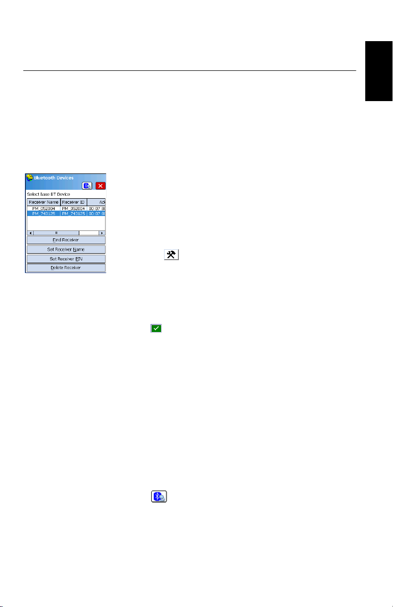
• Tap on . This opens the Bluetooth Devices window.
• Tap Find Receiver. Wait until FAST Survey lists the
Bluetooth identifiers of the base and rover. The list
appears in a new window.
• Highlight the Bluetooth identifier corresponding to the
base.
• Tap . This takes you back to the previous screen where
the selected Bluetooth identifier remains highlighted in
the list. The following actions may be performed on the
selected receiver using the following buttons:
• Set Receiver Name: By default, the “Receiver Bluetooth
Identifier” of the detected receiver is assigned to this
parameter. You may use a more self-explanatory name
to identify your base (e.g.: “MyBase”).
• Set Receiver PIN: Do not use this button. In its default
configuration, your equipment does not request a PIN
code to allow a peripheral device to connect to it via
Bluetooth.
• Delete Receiver: Removes the selected receiver from the
list of remote receivers detected by Bluetooth.
English
• Tap to connect the data collector to the base via
Bluetooth and then configure the base according to your
needs (see Configuring a Base on page 9).
• Later, you will establish a Bluetooth connection with the
rover. The process will start when you tap Equip>GPS Rover
7
Page 16
English
Switching Between
Base and Rover
Subsequent Uses In the next sessions of FAST Survey, the software will prompt
to configure the rover (see Configuring a Rover on
page 21). From the Comms tab, you will be able to access
the Bluetooth Devices window and select the rover
receiver from the list of remote receivers detected by
Bluetooth, in the same way as you did for the base.
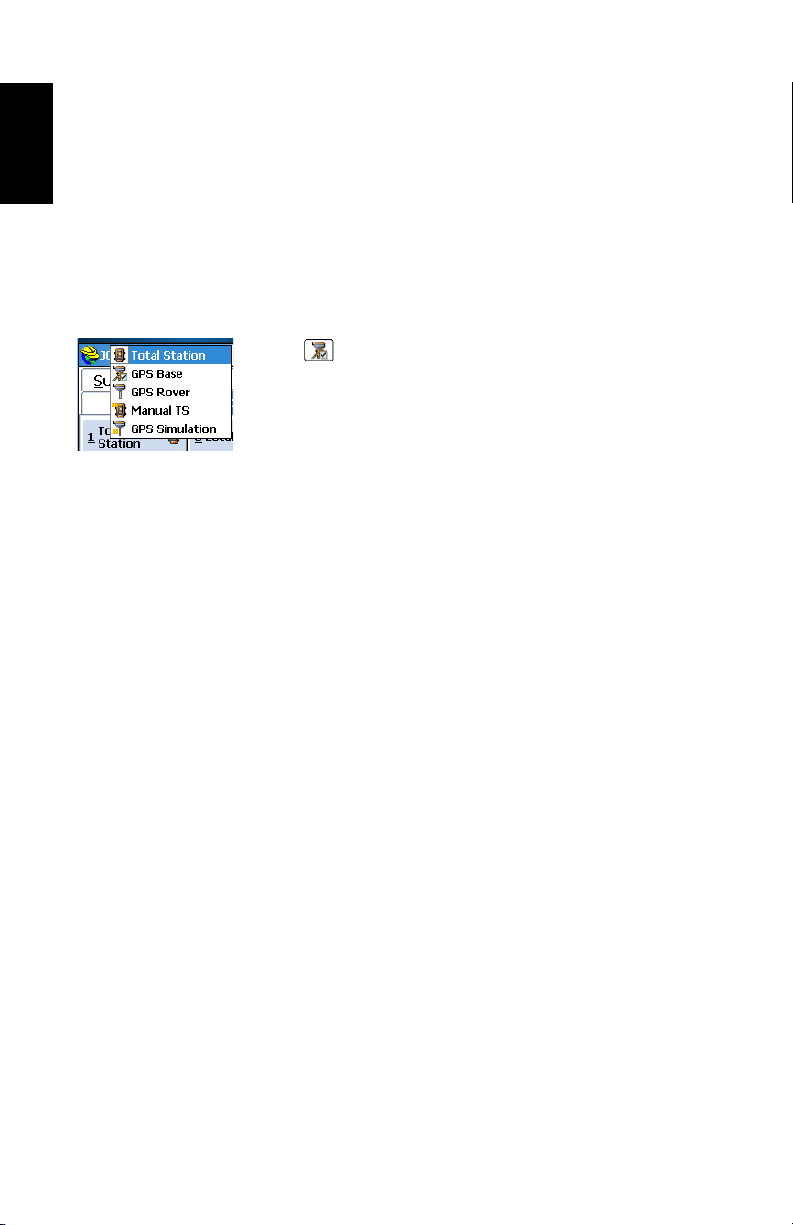
During a FAST Survey session, you can quickly change the
receiver you are communicating with (provided the receiver
you want to communicate with is within Bluetooth range).
The icon located in the upper-right corner of the FAST
Survey window allows you to change receivers. Tap on this
icon and then:
• Select GPS Base to switch to the base,
• Or select GPS Rover to switch to the rover.
NOTE: If you examine more carefully this icon, you will see
that it changes aspect (base or rover icon) depending on
which receiver is currently communicating with FAST Survey.
In addition, on the Equip menu, a small check box appears in
the icon inside either the GPS Rover or GPS Base button to
indicate which connection is active.
you to re-activate the Bluetooth connection you last
established in the previous session, or simply work without a
connection. If you choose the first option, FAST Survey will
automatically re-establish the connection, provided the
concerned receiver is still on and within Bluetooth range.
8
Page 17

Configuring a Base
The following Spectra Precision GNSS receivers may be used
as a base: ProMark 800, EPOCH 50, ProFlex 800 or
ProMark 220.
Prerequisites For ProMark 220:
• If you are using the internal GSM modem, insert the SIM
• If you are using an external radio, connect that radio to the
• Connect the external antenna to the receiver
• Power on the receiver, run FAST Survey and open a job
• Set the tracking mode using GNSS Toolbox. FAST Survey
card making possible the use of the modem.
receiver using a POGO cable (see Using an External Radio
with a ProMark 220 on page 53).
file.
will only be able to work from the signals selected with this
utility.
suming ProMark 220 is the currently selected type
As
–
of GNSS receiver in FAST Survey (Current tab),
running GNSS Toolbox from within FAST Survey is
simply done by selecting Equip > GPS Utilities > GNSS
Toolbox > GNSS Settings.
– Select the desired option from the Tracking mode drop-
down list. You can also set the elevation mask, enable
or disable the use of SBAS and QZSS and preset the
model of external antenna used.
– Then tap OK twice to return to the Equip menu.
English
For all other receivers:
• If you are using a GSM modem (whether internal or
external), insert the SIM card making possible the use of
the modem.
• If you are using an external radio transmitter, connect that
radio to the receiver and turn it on.
• Connect the external GNSS antenna (ProFlex 800).
• Power on the GNSS receiver and data collector.
• Run FAST Survey and open a job file.
9
Page 18
English
Configuration
Steps
In FAST Survey, tap on the Equip tab and then on the GPS Base
button. A message may appear asking you to confirm your
choice of configuring a base. Tap Yes. This opens the Current
tab of the GPS Base window. You will have to go through four
different configuration tabs (only three for ProMark 220)
before the base is configured and made operational.
Legend used in all the tables below:
“•” (blue background): The parameter exists for the considered GNSS receiver
and needs to be set to some value.
<Blank>: The parameter does NOT exist for the considered receiver.
“NA” (Non Applicable): The parameter exists but is irrelevant to the
considered receiver.
<Any_Other_Text> (orange background): The parameter exists for the
considered receiver and the text tells you the value you should assign to the
parameter.
Current Tab
Use this tab to identify the GNSS receiver FAST Survey has
to configure as a base.
Parameters EPOCH 50 ProMark 220 ProMark 800 ProFlex 800
Manufacturer, should
be set to:
Model, should be set
to:
Load/Save/Rename/
Delete Configuration
File
“Epoch 50”
• • • •
• • • •
“Spectra Precision”
“ProMark
100/120/200/
220”
“ProMark
800”
“ProFlex
800”
10
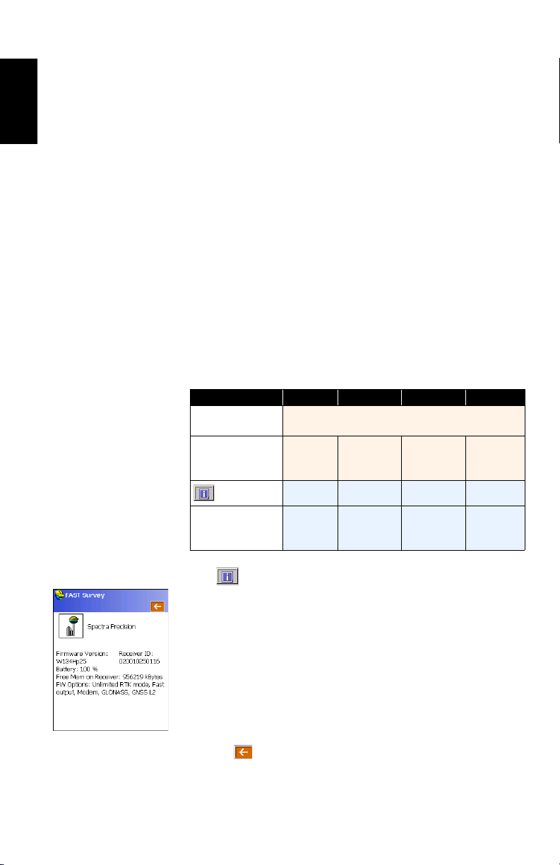
The button allows you to read the following information
from the receiver:
– Firmware version
– Receiver ID
– Power status
– Free memory space
– Firmware options installed.
FAST Survey will connect to the receiver via the currently set
connection to get this information.
Tap on to return to the Current tab.
Page 19
Comms Tab
Use this tab to set the connection between the data collector
running FAST Survey and the GNSS receiver you intend to
configure as a base.
ProMark 220 being both a GNSS receiver and a data
collector, the connection between these two parts is managed
internally and automatically. That’s why the Comms tab does
not exist for this receiver.
For all other Spectra Precision receivers, you can choose
between a Bluetooth or cable connection, as explained below.
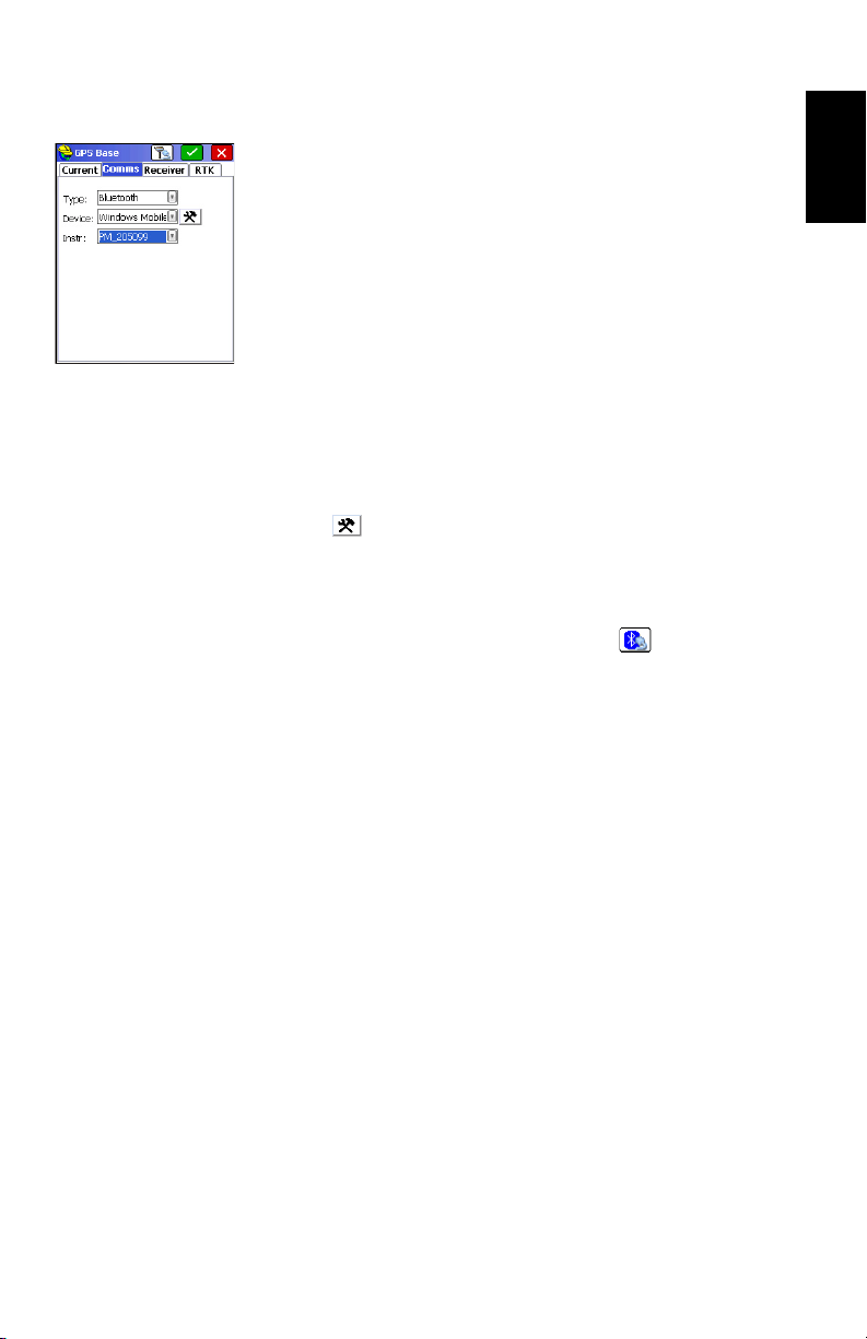
Bluetooth Connection:
• Select “Bluetooth” in the Typ e field. The Device field is
automatically set to “Windows Mobile”, which is the
option that should be used in all cases.
• Tap to access the Bluetooth driver.
• Tap Find Receiver to search for and list all the Bluetooth
devices located nearby. When it’s done, you should
recognize your GNSS receiver in the list.
• Select the receiver in the list and tap to activate the
Bluetooth connection with the receiver. This takes you
back to the Comms tab where the name of the connected
Bluetooth device now appears in the Instr field. More
information on Bluetooth is provided in How FAST Survey
Interfaces With a GNSS Receiver Via Bluetooth on page 7.
English
Cable Connection:
• Select “Cable” in the Typ e field.
• Configure the serial line (baud rate, parity, data bits, stop
bits).
11
Page 20

English
Receiver Tab
Use this tab to set the different operating parameters the
GNSS receiver will use as a base. The table below lists the
parameters you have to set on this tab (and sub-tabs),
depending on the GNSS receiver model you are using.
Parameters EPOCH 50 ProMark 220 ProMark 800 ProFlex 800
Antenna Selection NA
NGS
Vertical/Slant Height
Measurement
Antenna Height
Elevation Mask
Enable Ports B, F
and Ethernet
Position Rate
Advanced:
Use SBAS
Use GLONASS
Use Galileo
Send file after config NA
NMEA output port
Configure NMEA
Message
More:
Use QZSS
Use GPS
Source Datum
Virtual Antenna
“Vertical”
only
Internal/
External
• • • •
• • •
• • • •
• • • •
•
• • •
• • •
• • •
• • •
• • •
• • •
• • •
• • •
• • •
NA
• •
•
•
12
Additional Information is provided below for some of the
parameters listed above:
• NGS: With this option enabled, FAST Survey will correct
the antenna offset values to get an absolute offset. Keep
it disabled if relative offsets were used in some of the
measurements present in your job.
ition Rate: 1- or 2-Hz position output rate (irrelevant
Pos
•
to a base).
• Use GLONASS: Remember that activating the Use GLONASS
option in ProMark 220 will be effective only if you have
previously set the Tracking mode parameter in GNSS
Toolbox to “GPS L1+GLONASS L1” or “GPS/GLONASS
L1/L2”. As for the Use SBAS and Use QZSS options, only
the last setting made is effective, whether you do it from
GNSS Toolbox or from FAST Survey.
Page 21

• Send file after config: You may have a number of additional
commands executed (proprietary commands of the
“$PASH” type) when later you tap on to configure the
receiver. These commands must have been saved to a text
file, for example to a file created using Equip > GPS Utility
> Send command. To select the file you want the receiver to
execute when being configured, tap on the blue button
and highlight the corresponding file name.
NMEA Output Port: You may ask the base to output one or
•
more NMEA messag
ZDA, GST: see screen example) on the specified output
port. Once you have defined the output port (common to
all NMEA messages), tap on the Configure button and
then, for each desired NMEA message, select its output
rate (in Hertz or seconds).
• Use QZSS: Enables/disables the use of the QZSS (QuasiZenith Satellite System) constellation covering Japan and
the Far East.
• Use GPS: Enables/disables the use of the GPS
constellation (enabled by default).
• Source Datum: If GPS is used, this is a read-only field
providing the name of the datum (i.e. “W84”) on which
position solutions are computed. If GLONASS is used and
GPS is not used, you have the choice of which datum to
use: either “W84” (GPS datum) or “PZ90.02” (GLONASS
datum).
Virtual Antenna:
•
Enabling the virtual antenna, which is defined as the
generic “ADVNULLANTENNA” GNSS antenna, allows all
collected data to be decorrelated from the GNSS antenna
actually used at signal reception level. This may be useful
if you wish to post-process the raw data collected with a
rover from another manufacturer with the raw data
collected with this base.
es (GGA, GLL, RMC, VTG, GSV, GSA,
This option is disabled by default.
English
RTK Tab
Use this tab to define:
1. The type of device (“Device”) the GNSS receiver will use
to forward its corrections to users.
2. Possibly the network (“Network”) the base will rely upon to
deliver its corrections to users.
3. The type of corrections (“Message Type”) the GNSS
receiver will generate.
4. Optionally the Repeater mode for ProMark/ProFlex 800
receivers (Off or On).
13
Page 22

English
These settings are detailed below.
Device:
The device used may be one of the following:
1. An internal or external radio transmitter. Corrections will
be broadcast through a UHF radio link.
2. An internal or external GSM modem. Corrections will be
broadcast through either a network connection, of the
NTRIP or Direct IP type (TCP/IP or UDP/IP), or a phonelike connection, of the Direct Dial type (modem operated
in CSD mode). When a base delivers its corrections in
Direct Dial mode, you should provide the rover user with
the phone number allowing the rover to receive corrections
from the base.
Internal vs. external modems:
– With ProMark 220, the internal modem is located in
the GNSS receiver/data collector and the external one
in a third-party device.
– With ProMark/ProFlex 800, the internal modem is
located in the GNSS receiver – not in the data
collector– and the external modem is located either in
the data collector running FAST Survey, or in a thirdparty device.
– With EPOCH 50, the GSM modem can only be
external, either coming as a standalone device, or
being part of the data collector used to configure the
base (although that means in that case that the data
collector should stay connected to the EPOCH 50
throughout the base operating session).
14
3. Another device connected to the data collector through a
cable connection. This may be any radio transmitter not
supported directly by FAST Survey.
Page 23

The table below gives an overview of the devices available for
each GNSS receiver model and tells you which option to
choose in the Device field to make this device active.
Device EPOCH 50 ProMark 220
Internal
Radio
(TX)
Choice of
external
radios
(TX)
Internal
Modem
External
Modem
Cable or
Generic
Device
“Internal ADL”
Pacific Crest PDL
Satel 3AS
Airlink
SS900
ARWest
TRL-35
Satel 2AS
ARWest/Javad435
Wavecom
Wavecom Fasttrack IP
Satel Satelline
Pacific Crest ADL
“GSM Modem”, “Data
Collector Internet” or
“Data Collector Phone”
• • • •
Satel
Ashtech U-Link
ARF7474B EU
ARF7474A NA
Pacific Crest PDL
Pacific Crest ADL
“Data collector
Phone”
“Internet/Phone”
ProMark
“Internal
GSM”
“Data Collector Inter-
net” or “Data Collector
ProFlex
800
Ashtech U-Link
Magellan Radio
ARF7474B EU
ARF7474A NA
Pacific Crest PDL
Pacific Crest ADL
800
“Internal
ADL”
Satel
“Internal
GSM”
Phone”
NOTE 1: For EPOCH 50, “GSM Modem” refers to a GSM
modem device available as a standalone device.
NOTE 2: For more information on the supported radios, see
Additional Settings for External Radios on page 54.
English
15
Page 24

English
Network:
You need to set the Network field when a GSM modem is used.
For each GNSS receiver model, the table below lists the type
of connection you can implement (Network field), based on
the choice you make for “Device”.
Your Choice
for “Device”
“Internal GSM”
“Data Collector
Internet”
“Data Collector
Phone”
“Internet/
Phone”
“GSM Modem”
EPOCH 50 ProMark 220
TCP/IP Network
UDP/IP Network
Network field forced to “Phone Server” meaning the base is
configured to be called by a rover (modem used in CSD mode).
NTRIP
Direct Dial
TCP/IP Network
Direct Dial
ProMark
800
NTRIP
TCP/IP Network
UDP/IP Network
TCP/IP Network
UDP/IP Network
ProFlex
800
NOTE 1: In some cases, the Network field may include the
None option. This option does not correspond to any specific
operating mode. When this option is selected, the base will
NOT deliver any corrections through whatever existing
communication channel.
N
OTE 2: The internal GSM modem of the ProMark 800 and
ProFlex 800 CANNOT operate in Direct Dial (CSD mode).
Direct Dial is only possible using the data collector modem.
That means the data collector should stay connected to the
ProMark 800 or ProFlex 800 throughout the base operating
session.
More information is provided below about modem settings
(see 1. below) and how to define the network the base will
connect to. Two cases of network definitions are described:
NTRIP (see 2. below) and TCP/IP (see 3. below).
16
Page 25

1. Setting the chosen device (tap on next to Device):
Your Choice
for “Device”
“Internal GSM”
“Data Collector Internet”
“Data Collector Phone”
“Internet/
Phone”
“GSM Modem” EPOCH 50 Dial Mode (Analog/Digital)
Concerned
GNSS receiver
ProMark 800
ProFlex 800
ProMark 800
ProFlex 800
EPOCH 50
All
ProMark 220
Device Settings Required
• Power Management (Manual or Auto)
Band (850/1900, 900/1800 or 900/
•
1900)
• Provider (Cingular, T-Mobile, MoviStar,
User, Other). For the last two options,
define APN Server, APN User Name &
APN Password.
• Pin (pin code)
• Dial Mode (Analog or Digital)
• Auto-Dial (ON or OFF)
• 2G/3G mode (Auto or 2G only)
• Select ISP from list (a modem connection previously created with Windows
Mobile’s Connections utility).
(Disconnect button also available)
• For EPOCH 50 only, select the internal
data collector port through which corrections are forwarded to the data collector modem)
None, except for EPOCH 50 for which you
have to select the internal data collector
port through which corrections are forwarded to the data collector modem
Auto-Dial, On or Off. With this option
enabled, the connection to the last mount
point used (NTRIP), or to the last IP
address used (TCP/IP Network) will be
automatically re-established after a power
cycle. This option is irrelevant to a DirectDial connection and so should be kept disabled in that case.
English
NOTE: With EPOCH 50 configured to use the data
collector modem to send out corrections (2nd and 3rd
rows in the above table), the RTK tab asks you to define
the connection through which the EPOCH 50 sends out its
corrections. This is done by setting the Port field:
• Choose “Data” to have corrections flowing via
Bluetooth. That means both autonomous position
results and corrections will flow through the same
Bluetooth connection.
• Choose “COM 2” if you are using a cable between the
EPOCH 50 and the data collector. In that case the port
17
Page 26

English
used on EPOCH 50 side can only be port 2 (COM 2).
The port used on data collector side should be defined
when setting the chosen device.
2. Setting a base as an NTRIP source (applicable to all
ProFlex and ProMark receivers):
• Depending on the receiver used, choose the
appropriate device so you can set Network=“NTRIP”
(see the above two tables).
• Tap on , next to Network.
•In the Name drop-down list, overwrite “<New>” with
the name of the NTRIP broadcaster. Then enter the
NTRIP broadcaster’s IP address and port ID. Lastly,
enter the user name and password allowing the base to
provide corrections to this NTRIP service.
NOTE: For each new NTRIP broadcaster entry, first
select “<New>” from the Name drop-down list, and
then enter the NTRIP broadcaster’s parameters.
Reciprocally, when you want to delete an NTRIP
broadcaster entry, first select its name from the Name
drop-down list and then tap on the Delete button.
• Tap to validate your new settings. This takes you
back to the RTK tab.
• Further down on the screen, through , you may as
an option provide information describing your base,
which the NTRIP broadcaster will forward to users
through the NTRIP source table. The description of an
NTRIP source includes:
- Name: Base name
- Identifier: Base identifier
- Short Id: Abbreviated identification
- Typ e: Base model. FAST Survey will automatically
add the names of the GNSS frequencies processed by
the base after you have saved this base entry, e.g. you
first type “Spectra Precision” in this field, and once
you have saved the entry, this field will read “Spectra
Precision L1L2”.
- Format: Format of corrections generated by the base
- Misc: Use this field at your convenience.
- Send Rover Position to Network: Indicate whether the
base needs to acquire a rough position from a rover
before it can deliver corrections to that rover.
18
Page 27

The Position field will be automatically completed by
the software after you have saved the entry.
Here again, you may create several entries and use the
one matching your base’s current configuration.
3. Setting a base to deliver corrections to a static IP address:
• Choose the appropriate device so you can set
Network=“TCP/IP Network” (or “UDP/IP Network”).
• Through the TCP/IP Network drop-down list displayed
fu
rther down on the screen, select the name of the
base corresponding to your base configuration.
If the TCP/IP Network list is blank, tap on next to
it. In the Name drop-down list, overwrite “<New>” with
the name of the base. Then enter its IP address and IP
port.
NOTE: For each new base entry, first select “<New>”
from the Name drop-down list, and then enter the base
parameters. Reciprocally, when you want to delete a
base entry, first select its name from the Name dropdown list and then tap on the Delete button.
• Tap to validate the new base entry and return to the
RTK tab. The name of that new base is now the current
selection in the TCP/IP Network field.
Message Type:
The table below indicates all the possible message types each
receiver model can generate.
English
Corrections
ATO M
ATOM C ompac t
ATOM Super Compact
CMR
CMR+
RTCM 2.3
RTCM 3
RTCM DGPS
DBEN
EPOCH 50ProMark
• • • •
• • • •
• • • •
• • • •
ProMark
220
• • •
• • •
• • •
• • •
800
• •
ProFlex
800
19
Page 28

English
Completing the
Base Configuration
Phase
• After you’ve been through all the tabs, tap to save all
your settings.
• FAST Survey then asks you to set the base position.
Depending on the chosen method, follow the instructions
displayed on the screen to define this position (see also
Setting the Base Position With FAST Survey on page 56
for more information). This completes the base
configuration phase, and the base should now start
operating as configured.
20
Page 29

Configuring a Rover
The following Spectra Precision GNSS receivers may be used
as a rover: ProMark 700, ProMark 800, EPOCH 50, ProFlex
800 or ProMark 220.
Prerequisites For ProMark 220:
• If you are using the internal GSM modem, insert the SIM
• If you are using an external radio, connect that radio to the
• Connect the external antenna to the receiver
• Power on the receiver, run FAST Survey and open a job
• Set the tracking mode using GNSS Toolbox. FAST Survey
English
card making possible the use of the modem.
receiver using a POGO cable (see Using an External Radio
with a ProMark 220 on page 53).
file.
will only be able to work from the signals selected with this
utility.
– Assuming ProMark 220 is the currently selected GNSS
receiver in FAST Survey (Current tab), running GNSS
Toolbox from within FAST Survey is simply done by
selecting Equip > GPS Utilities > GNSS Toolbox > GNSS
Settings.
– Select the desired option from the Tracking mode drop-
down list. You can also set the elevation mask, enable
or disable the use of SBAS and QZSS and preset the
model of external antenna used.
– Then tap OK twice to return to the Equip menu.
For all other receivers:
• If you are using a GSM modem (whether internal or
external), insert the SIM card making possible the use of
the modem.
• If you are using an external radio receiver, connect that
radio to the receiver and turn it on.
• Make sure an external GNSS antenna is connected
(ProFlex 800).
• Power on the GNSS receiver and data collector.
• Run FAST Survey and open a job file.
21
Page 30

English
Configuration
Steps
In FAST Survey, tap on the Equip tab and then on the GPS
Rover button. A message may appear asking you to confirm
your choice of configuring a rover. Tap Yes . This opens the
Current tab of the GPS Rover window. You will have to go
through four different configuration tabs (only three for
ProMark 220) before the rover is configured and made
operational.
Legend used in all the tables below:
“•” (blue background): The parameter exists for the considered GNSS receiver
and needs to be set to some value.
<Blank>: The parameter does NOT exist for the considered receiver.
“NA” (Not Applicable): The parameter exists but is irrelevant to the
considered receiver.
<Any_Other_Text> (orange background): The parameter exists for the
considered receiver and the text tells you the value you should assign to the
parameter.
Current Tab
Use this tab to identify the GNSS receiver FAST Survey has
to configure as a rover.
22
Parameters
Manufacturer,
should be set to:
Model, should
be set to:
Load/Save/
Rename/Delete
Configuration
File
EPOCH 50ProMark
“Epoch
“ProMark
100/120/
50”
200/220”
• • • •
• • • •
220
“Spectra Precision”
ProMark
700
“ProMark
700”
ProMark
800
“ProMark
800”
•
•
ProFlex
800
“ProFlex
800”
The button allows you to read the following information
from the receiver:
– Firmware version
– Receiver ID
– Power status
– Free memory space
– Firmware options installed.
FAST Survey will connect to the receiver via the currently set
connection to get this information.
Tap on to return to the Current tab.
Page 31

Comms Tab
Use this tab to set the connection between the data collector
running FAST Survey and the GNSS receiver you intend to
configure as a rover.
ProMark 220 being both a GNSS receiver and a data
collector, the connection between these two parts is managed
internally and automatically. That’s why the Comms tab does
not exist for this receiver.
For all other Spectra Precision receivers, you can choose
between a Bluetooth or cable connection, as explained below.
Bluetooth Connection:
• Select “Bluetooth” in the Typ e field. The Device field is
automatically set to “Windows Mobile”, which is the
option that should be used in all cases.
• Tap to access the Bluetooth driver.
• Tap Find Receiver to search for and list all the Bluetooth
devices located nearby. When it’s done, you should
recognize your GNSS receiver in the list.
• Select the receiver in the list and tap to activate the
Bluetooth connection with the receiver. This takes you
back to the Comms tab where the name of the connected
Bluetooth device now appears in the Instr field. More
information on Bluetooth is provided in How FAST Survey
Interfaces With a GNSS Receiver Via Bluetooth on page 7.
English
Cable Connection:
• Select “Cable” in the Typ e field.
• Configure the serial line (baud rate, parity, data bits, stop
bits).
23
Page 32

English
Receiver Tab
Use this tab to set the different operating parameters the
GNSS receiver will use as a rover. The table below lists the
parameters you have to set on this tab (and sub-tabs),
depending on the GNSS receiver model you are using.
Parameters
Antenna Selection NA
NGS
Vertical/Slant Height
Measurement
Antenna Height
Elevation Mask
Enable Ports B, F and
Ethernet
Position Rate
Store Vectors in Raw
Data
Advanced:
Base Receiver Type
Use SBAS
Use GLONASS
Use Galileo
Send file after config NA
NMEA output port
Configure NMEA
Message
More:
Ambiguity Fixing
Use QZSS
Use GPS
Virtual Antenna
Use RTK Datum
(RTCM 3.1)
Use RTK XYZ Posi-
tion (RTCM 3.1)
EPOCH 50ProMark
“Vertical”
only
Internal/
External
• • • •
• • • • •
• • • • •
• •
• • • • •
ProMark
220
• • • •
• • •
• • •
• • •
•NA• •
• • •
• • •
• • •
• • •
• • •
• • •
• • •
• • •
ProMark
700
NA NA
800
• •
ProFlex
800
•
•
24
Additional Information is provided below for some of the
parameters listed above:
• NGS: With this option enabled, FAST Survey will correct
the antenna offset values to get an absolute offset. Keep
it disabled if relative offsets were used in some of the
measurements present in your job.
Page 33

• Position Rate: 1- or 2-Hz position output rate.
• Store Vectors in Raw Data: With this option enabled, FAST
Survey will save the computed vectors into the job (into
the RW5 file)
.
• Base Receiver Type: You may specify the manufacturer of
the base providing your rover with corrections. This will
ease the process through which the rover can decode
these corrections. If you have no idea which receiver
model is used at the base, select AUTOMATIC and the rover
will automatically find out the manufacturer of the base
receiver.
• Use GLONASS: Remember that activating the Use GLONASS
option in ProMark 220 will be effective only if you have
previously set the Tracking mode parameter in GNSS
Toolbox to “GPS L1+GLONASS L1” or “GPS/GLONASS
L1/L2”. As for the Use SBAS and Use QZSS options, only
the last setting made is effective, whether you do it from
GNSS Toolbox or from FAST Survey.
• Send file after config: You may have a number of additional
commands executed (proprietary commands of the
“$PASH” type) when later you tap on to configure the
receiver. These commands must have been saved to a text
file, for example to a file created using Equip > GPS Utility
> Send command. To select the file you want the receiver to
execute when being configured, tap on the blue button
and highlight the corresponding file name.
NMEA Output Port: You may ask the rover to output one or
•
more NMEA messages (GGA, GLL, RMC, VTG, GSV, GSA,
ZDA, GST) on the specified output port. Once you have
defined the output port (common to all NMEA
messages), tap on the Configure button and then, for
each desired NMEA message, select its output rate (in
Hertz or seconds).
• Ambiguity Fixing (see table below).
Choice Definition
Choose this option if you only need decimeter accuracy (position
Float
status will never go to “Fixed”).
95.0 95% confidence level
99.0 99% confidence level (default and recommended setting)
99.9% confidence level
99.9
English
• Use QZSS: Enables/disables the use of the QZSS (QuasiZenith Satellite System) constellation covering Japan and
the Far East.
25
Page 34

English
• Use GPS: Enables/disables the use of the GPS
constellation (enabled by default).
• Source Datum: If GPS is used, this is a read-only field
providing the name of the datum (i.e. “W84”) on which
position solutions are computed. If GLONASS is used and
GPS is not used, you have the choice of which datum to
use: either “W84” (GPS datum) or “PZ90.02” (GLONASS
datum).
• Virtual Antenna: This option is disabled by default.
Enabling the virtual antenna, which is defined as the
generic “ADVNULLANTENNA” GNSS antenna, allows all
collected data to be decorrelated from the GNSS antenna
actually used at signal reception level. This may be useful
if you wish to post-process the collected raw data using
base raw data collected with a base from another
manufacturer.
• Use RTK Datum (RTCM 3.1): Enable this option if you want
the rover to compute position solutions on the same
datum as the one used by the base (this function will be
effective only if the rover receives RTCM 3.1 messages
1021 and 1023 from the base).
• Use RTK XYZ Position (RTCM 3.1): Enable this option if you
want the rover to compute position solutions in the same
coordinate system as the one used by the base (this
function will be effective only if the rover receives RTCM
3.1 message 1025 from the base). Enabling this option
makes sense only if Use RTK Datum (RTCM 3.1) is also
enabled.
26
RTK Tab
Use this tab to define:
1. The type of device (“Device”) the GNSS receiver will use
to acquire corrections.
2. Possibly the network (“Network”) the rover will connect to
to acquire corrections.
3. Whether the rover is expected to return its current position
before corrections can be sent back to it.
Page 35

These settings are detailed below.
Device:
The device used may be one of the following:
1. An internal or external radio receiver. Corrections will be
received through a UHF radio link.
2. An internal or external GSM modem. Corrections will be
received through either a network connection, of the
NTRIP or Direct IP type (TCP/IP or UDP/IP), or a phonelike connection, of the Direct Dial type (modem operated
in CSD mode). To acquire corrections from a base
delivering its corrections in Direct Dial mode, you should
have been given the phone number so the rover can call
the base.
Internal vs. external modems:
– With ProMark 220, the internal modem is located in
the GNSS receiver/data collector and the external one
in a third-party device.
– With ProMark/ProFlex 800, the internal modem is
located in the GNSS receiver – not in the data
collector– and the external modem is located either in
the data collector running FAST Survey, or in a thirdparty device.
– With EPOCH 50, the GSM modem can only be
external, either coming as a standalone device, or
being part of the data collector used to configure the
rover.
3. Another device connected to the data collector through a
cable connection. This may be any radio receiver not
supported directly by FAST Survey.
English
27
Page 36

English
The table below gives an overview of the devices available for
each GNSS receiver model and tells you which option to
choose in the Device field to make this device active.
Device EPOCH 50 ProMark 220
Internal
Radio
(RX)
Choice of
external
radios
(RX)
Internal
Modem
External
Modem
Cable or
Generic
Device
“Internal ADL” “Internal ADL”
Pacific Crest PDL
Satel 3AS
Airlink
SS900
ARWest
TRL-35
Satel 2AS
ARWest/Javad435
Wavecom
Wavecom Fasttr. IP
Satel Satelline
Pacific Crest ADL
“GSM Modem”,
“Data Collector Inter-
net” or “Data Collec-
tor Phone”
• • • • •
Satel
Ashtech U-Link
ARF7474B EU
ARF7474A NA
Pacific Crest PDL
Pacific Crest XDL
Pacific Crest ADL
“Internet/Phone”
or “Data collector
Phone”
NOTE 1: For EPOCH 50, “GSM Modem” refers to a GSM
modem device available as a standalone device.
NOTE 2: The ProMark 800 built-in radio (“Internal ADL”) is
a radio receiver only whereas the radio used in the EPOCH 50
and ProFlex 800, also labeled “Internal ADL”, is a radio
transceiver.
NOTE 3: For more information on the supported radios, see
Additional Settings for External Radios on page 54.
ProMark
“Data Collector Internet” or “Data Collector
ProMark 800 ProFlex 800
700
Satel
ARF7474B EU
ARF7474A NA
“Internal GSM”
Phone”
Satel
Ashtech U-Link
ARF7474B EU
ARF7474A NA
28
Page 37

Network:
You need to set the Network field when a GSM modem is used.
For each GNSS receiver model, the table below lists the type
of connection you can implement (Network field), based on
the choice you make for “Device”.
Your Choice
for “Device”
“Internal GSM”
“Data Collector Internet”
“Data Collector Phone”
“Internet/
Phone”
“GSM Modem” Direct Dial
EPOCH 50 ProMark 220
TCP/IP Direct
UDP/IP Direct
NTRIP
SpiderNet
TCP/IP Direct
NTRIP
SpiderNet
Direct Dial
Direct Dial
ProMark
700
ProMark
800
TCP/IP Direct
NTRIP
SpiderNet
TCP/IP Direct
UDP/IP Direct
NTRIP
SpiderNet
ProFlex
800
NOTE 1: In some cases, the Network field may include the
None option. This option does not correspond to any specific
operating mode. When this option is selected, the rover will
NOT receive any corrections through whatever existing
communication channel.
NOTE 2: The internal GSM modem of the ProMark 800 and
ProFlex 800 CANNOT operate in Direct Dial (CSD mode).
Direct Dial is only possible using the data collector modem.
More information is provided below about modem settings
(see 1. below) and how to define the network the rover will
connect to. Two cases of network definitions are described:
NTRIP (see 2. below) and TCP/IP (see 3. below). An example
of Direct-Dial connection is also provided (see 4. below).
English
29
Page 38

English
1. Setting the chosen device (tap on next to Device):
Your Choice
for “Device”
“Internal GSM”
“Data Collector Internet”
“Data Collector Phone”
“Internet/
Phone”
“GSM Modem” EPOCH 50 Dial Mode (Analog/Digital)
Concerned
GNSS receiver
ProMark 800
ProFlex 800
ProMark 800
ProFlex 800
EPOCH 50
All
ProMark 220
Device Settings Required
• Power Management (Manual or Auto)
Band (850/1900, 900/1800 or 900/
•
1900)
• Provider (Cingular, T-Mobile, MoviStar,
User, Other). For the last two options,
define APN Server, APN User Name &
APN Password.
• Pin (pin code)
• Dial Mode (Analog or Digital)
• Auto-Dial (ON or OFF)
• 2G/3G mode (Auto or 2G only)
• Select ISP from list (a modem connection previously created with Windows
Mobile’s Connections utility).
(Disconnect button also available)
• For EPOCH 50 only, select the internal
data collector port receiving corrections
from the data collector modem).
None, except for EPOCH 50 for which you
have to select the internal data collector
port receiving corrections from the data
collector modem.
Auto-Dial, On or Off. With this option
enabled, the connection to the last mount
point used (NTRIP), or to the last IP
address used (TCP/IP Network) will be
automatically re-established after a power
cycle. This option is irrelevant to a DirectDial connection and so should be kept disabled in that case.
30
NOTE: With EPOCH 50 configured to use the data
collector modem to acquire corrections (2nd and 3rd rows
in the above table), the RTK tab asks you to define the
connection through which corrections are forwarded to the
EPOCH 50. This is done by setting the Port field:
• Choose “Data” to have corrections flowing via
Bluetooth. That means both RTK position results and
corrections will flow through the same Bluetooth
connection (but in opposite directions).
• Choose “COM 2” if you are using a cable between the
EPOCH 50 and the data collector. In that case the port
used on EPOCH 50 side can only be port 2 (COM 2).
Page 39

The port used on data collector side should be defined
when setting the chosen device.
2. Setting a rover to receive corrections from an NTRIP
network:
• Depending on the receiver used, choose the
appropriate device so you can set Network=“NTRIP”
(see the above two tables).
• Tap on , next to Network.
•In the Name drop-down list, overwrite “<New>” with
the name of the NTRIP broadcaster. Then enter the
NTRIP broadcaster’s IP address and port ID. Lastly,
enter the user name and password allowing the rover to
acquire corrections from this NTRIP service.
NOTE: For each new NTRIP broadcaster entry, first
select “<New>” from the Name drop-down list, and
then enter the NTRIP broadcaster’s parameters.
Reciprocally, when you want to delete an NTRIP
broadcaster entry, first select its name from the Name
drop-down list and then tap on the Delete button.
• Tap to validate your new settings. This takes you
back to the RTK tab.
• Further down on the screen, through , you may
read advanced information describing the NTRIP
broadcaster (NTRIP source table). The description of
an NTRIP source includes:
- Name: Base name
- Identifier: Base identifier
- Short Id: Abbreviated identification
- Typ e: Base model.
- Format: Format of corrections generated by the base
- Misc: Additional information the NTRIP broadcaster
would like to share with users.
- Send Rover Position to Network: Indicate whether the
NTRIP network needs to acquire a rough position from
the rover before it can deliver corrections to that rover.
3. Setting a rover to receive corrections from a static IP
address:
• Choose the appropriate device so you can set
Network=“TCP/IP Direct” (or “UDP/IP Direct”).
English
31
Page 40

English
•
hrough the Base ID drop-down list displayed further
T
down on the screen, select the name of the base you
want to work with.
If the Base ID list is blank, tap on next to it. In the
Name drop-down list, overwrite “<New>” with the
name of the base. Then enter its IP address and IP
port.
NOTE: For each new base entry, first select “<New>”
from the Name drop-down list, and then enter the base
parameters (Name, Address, Port, Send Rover Position
to Network?). Reciprocally, when you want to delete a
base entry, first select its name from the Name dropdown list and then tap on the Delete button.
• Tap to validate the new base entry and return to the
RTK tab. The name of that new base is now the current
selection in the Base ID field.
4. Setting a rover to make a phone call to the base (Direct
Dial):
– Choose the appropriate device so you can set
Network=“Direct Dial”).
– Tap on next to the Base ID field to name the base
and enter its phone number. For EPOCH 50 and
ProMark 700, you additional need to specify the type
of corrections delivered by the base.
Configuration
32
End of Rover
Phase
• After you’ve been through all the tabs, tap to save all
your settings. The rover will start operating as configured.
Page 41

Checking For a “Fixed” Position Solution
After the data link has been established, the rover starts
acquiring corrections data from the selected source. Note
that some rover models will automatically recognize the
format of the received data (ATOM, RTCM2.3, RTCM 3, CMR,
CMR+, DBEN). Do the following before starting your survey:
•In the Equip menu, tap on the Monitor/Skyplot button
• Read the different parameters displayed on the screen.
You should see the HRMS and VRMS rapidly decrease
from a few meters to less than 10 to 20 mm, while the
position status switches from “AUTO” to “FLOAT” and
finally “FIXED”.
Other screens are available from within the Monitor/Skyplot
function showing the details of the constellation, of the
base position and of the RTK position solution:
English
33
Page 42

English
In NTRIP and Direct IP modes, a Disconnect/Connect
button is available on the Quality tab to easily control the
network connection. There is also a horizontal bar showing
the GSM signal level.
In Direct Dial mode, a Hang up button is available on the
same tab to terminate the connection with the base.
• Tap after you have made sure the FIXED position
status is settled. This takes you back to the FAST Survey
menu from which you can start your survey.
34
Page 43

Using FAST Survey’s Basic RTK Functions
Uploading
Stakeout Points
In your office, do the following:
• Connect the receiver or data collector to your office
computer using the USB data cable. For ProMark 1x0 or
2x0, place the receiver on its docking station and connect
the docking station to the computer via the USB cable.
• Make sure Windows Mobile Device Center (or ActiveSync
for older computers) is installed on your computer and is
allowed to perform USB connections. If you do not have
this utility installed yet, download the latest version from:
http://www.microsoft/en-us/download/
Using Spectra Precision Survey Office (SPSO):
• Run SPSO on your computer.
• Open the job containing the stakeout points.
• In the Project Explorer pane (on the left), select the points
you want to export.
• On the menu bar, select File then Export. This opens the
Export pane (on the right).
• In the Export pane, choose the file format by clicking on
Custom, then on “P, N, E, elev, Code”.
• Further down in the Export pane, name the export file as
desired (default is <open_job_name>.csv), choose a
folder on the computer where to save it and click Save.
• Further down in the Export pane, click on the Export
button to export the selected points.
• When done, copy the file to a folder of your choice on the
receiver.
• On the receiver, run FAST Survey and open a job.
• On the FAST Survey menu, select the File tab and then tap
on Import/Export.
• Tap Import ascii File. Select “User-Defined” in the Type
field, “P, Y, X, Z, D” in the Format field.
• Tap Select File, select “CSV File” in the Typ e field, browse
to the folder containing the CSV file and highlight the file.
• Tap . Fast Survey takes you back to the Import Ascii
dialog showing the content of the selected CSV file.
• Tap again if that content is as expected,
• Tap again to confirm that you want the points to be
imported to the open job. When done, FAST Survey
indicates the number of imported points. Tap OK.
English
35
Page 44

English
Using GNSS Solutions:
• Run GNSS Solutions on your office computer.
• Open the project containing the stakeout points you want
to transfer to the receiver or data collector as your job.
• On the project map view, select all the reference and
target points making up your job.
• Select Project>Upload Positions to External Device..
• Select RTK Job and FAST Survey data collector.
• Click OK.
• Name the job (e.g. MYJOB). Keep the Selected Targets and
References option selected and click OK. This opens the
Data Transfer dialog box.
• In the combo box, select Active Sync and keep Automatic
transfer enabled.
• Click OK to establish the connection with the receiver or
data collector and upload the job (to \My Device\Program
Files\FAST Survey\Data\).
• After the job has been uploaded, turn off the receiver or
data collector, disconnect the USB cable and go to the
field with your surveying equipment to stake out your
points.
Staking Out Points 1. Run FAST Survey and open the job containing the points
you want to stake out.
2. Tap on the Survey tab and then select Stake Points. The
screen now displayed allows you to stake out points.
3. On this screen, FAST Survey asks you to choose the point
you want to stake out. You can either type in its
coordinates in the Northing, Easting and Elevation fields, or
select a pre-defined point from the points list (see File>
Points). You can also define graphically the point by
tapping on the point on the graphic screen, or define the
point according to azimuth, slope and horizontal distance.
36
Page 45

4. Once you have chosen a point, tap . A graphic screen
Name of
stakeout point
Coordinates of
stakeout point
Provides access to point list.
Example of points list:
Provides access to graphic screen
is now displayed to help you head for the point.
English
Provides access to
screen below (Select
“Text” in menu)
Next stakeout point
Logs stakeout point
Current status of
position solution
Name, coordinates of
stakeout point, quality data,
deviation data
(Use the up/down arrow
keys to show/hide this
information)
Yellow helmet gives
access to Function
Menu!
Takes you back to the
point selection screen
Zoom settings
5. When the distance to the stakeout point is too small to be
clearly seen on this screen, tap on the surveyor’s helmet
Configures general
case of point logging
Provides access to
monitor screen
Your current position
and heading
Stakeout point (target)
GNSS antenna height
Viewing parameters
in the upper-left corner and select Tex t from the menu that
pops up.
A new screen appears giving a more accurate view of the
remaining distance to the stakeout point. (If you want to
return to the previous screen, just select Graph in the same
menu.)
37
Page 46

English
Stakeout point (target)
Provides access to
previous screen
(Select “Graph” in menu)
Your current position
and heading
Used to select which
guidance data to display
(underneath)
Used to select which
guidance data to display
for the point: coordinates
or quality data
Current status of
position solution
When the remaining distance is within the stakeout
tolerance (this parameter can be changed in
Equip>Tol eran ces ), markers appear in the four corners of
the target. You can now set a stake on this point.
6. Tap on the STORE button if you want to store the position
of this point. You will be notified if the values of HRMS
and VRMS exceed the tolerances set for these two
parameters in Equip>Tol eran ces . A new screen is then
displayed showing the coordinates of both the staked and
design points.
38
7. Tap if you agree. The “Point Stored” message appears
briefly. The screen then comes back to the Stake Points
screen where you can choose the next point to be staked.
8. After staking out all your points, tap in the upperright corner of the screen to return to the menu.
Page 47

Logging Points 1. Tap on the Survey tab and then on Store Points. The screen
now displayed allows you to log all your points.
The figure below summarizes all the functions available
from that screen.
Logging point
Logging points with
position averaging
Logging point
(general case)
with offset
Configures general
case of point logging
Provides access to
monitor screen
English
Enter point name
and description in
these two fields
Current position and
related quality figures
Your current position
and heading
Graphic display area
GNSS antenna height
Zoom settings
Viewing parameters
2. Type in the point name and description in the
corresponding two fields (see above)
3. Tap on the “A” button
4. Enter the number of readings you want before FAST
Survey is allowed to compute an average position for this
point.
For example, type in “5” and tap .
Messages follow successively indicating that the system is
taking the five requested readings. Then FAST Survey
displays the average coordinates it has determined for the
point.
5. Tap if you agree. The “Point Stored” message appears
briefly. The screen then shows the location of the point
together with its name and description.
6. After logging all your points, tap in the upper-right
corner of the screen to return to the menu.
Logging a Line 1. On the Survey tab, select the Auto by Interval function. Two
different modes are possible: Time or Distance.
39
Page 48

English
2. If you choose Distance, enter the horizontal and vertical
increment value respectively in the X/Y and Z fields,
according to the chosen unit. If you choose Time, enter the
increment value, in seconds.
3. Enter a point Id. for the start point in the Starting Pt ID
field. This field will be incremented by one after each
point logging. Initially, the Point Id. may only consist of
letters (e.g. “ABCD”). FAST Survey will then increment
the Point Id. as follows: ABCD1, ABCD2, etc.
4. Tap to switch to the graphic screen (see figure below)
and start logging the series of points along the line.
Used to
pause/resume data
logging
Used to log a point’s
position manually
Current status of
position solution
Point ID incremented
automatically
Current position and
related quality figures
Configures general
case of point logging
Provides access to
monitor screen
Your current position
and heading
Graphic display area
GNSS antenna height
Zoom settings
Viewing parameters
The S button lets you instantly log the position of a point.
The pause button allows you to pause data logging in
continuous mode.
If data logging in continuous mode is paused, you can still
continue to log points in manual mode using the S button.
Tap the pause button again to resume data logging in
continuous mode.
If you directly tap to come back to the main menu,
data logging in continuous mode is automatically stopped.
Downloading RTK
Points
40
Go back to your office and connect the
receiver or data
collector to your office computer using a USB data cable.
For ProMark 1x0 or 2x0, place the receiver on its docking
station and connect the docking station to the computer via
the USB cable.
Page 49

To Spectra Precision Survey Office (SPSO)
• Copy the FAST Survey job (crd job) to any folder on your
computer.
• Run SPSO.
•Open the project in which you want to add the points
collected in the field with FAST Survey.
• On the SPSO menu bar, select File then Import. This opens
the Import pane on the right. SPSO lists all the files found
on the computer that may be imported to SPSO. Your crd
job file should be present in that list.
• Select your crd file and click on the Import button at the
bottom of the Import pane. Once the file has been
imported, the imported points can be seen on the job’s
Plan View.
• Save the project.
To GNSS Solutions
•Run GNSS Solutions on your office computer.
• Open the project in which to add the points from the field.
• Select Project>Download Positions from External Device..
• Select RTK Results and FAST Survey data collector.
• Click OK. This opens the Data Transfer dialog box.
• In the combo box, select ActiveSync, enable Automatic
Transfer and click OK. This opens a new window listing all
the jobs stored in the data collector.
• Select the job you want to download (e.g. “MYJOB”) and
click OK. This starts the download process.
English
Running
Localization in an
RTK Project
Vector information relative to surveyed points is available only
in .rw5 files. FAST Survey saves vector information directly in
this file format and so does not create O-files that would
contain such information.
Choosing the Localization Method
• With your job open in FAST Survey, tap on the Equip tab
and then on the Localization button. This opens the
Localization window with the System tab shown first.
41
Page 50

English
List of reference points
you want to include in the
localization process
Edits the selected
reference point
Deletes the selected
reference point
Adds a new reference
point to the list
Loads a list of reference points
from a DAT or LOC file
Controls the content of the selected row, in
the points list above, where either the
geographic or local coordinates of the
reference point are displayed
Enables/disables the selected
reference point for/from the
localization process
Saves the list of current
reference points as a LOC or
DAT file
Provides access to Solution
Monitoring screen
For your information, this tab shows the name of the
projection selected earlier for the project (see File>Job
Settings>System). Choosing another projection here would
change the projection used in the job. It is your
responsibility to have the right projection selected on
which the localization process is going to be run.
• Tap on the GPS tab and select your localization methods
for multi-point and one-point localizations. If you choose
“Helmert” as the localization method, the one-point
method selection is grayed.
One-Point or Multi-Point Localization
1. Tap on the Points tab. This tab allows you to define the
reference points used as the input to the localization
process.
42
For each of the available reference points, you need to
enter the local coordinates and then the WGS84
coordinates, as measured by your equipment.
Page 51

2. Tap Add to define the first reference point. A new window
(Local Point) is displayed allowing you to do that. To add
a reference point that already exists in the job, do one of
the following:
• Type its name in the Point From File field. This
automatically updates the window with the point’s
local coordinates.
• Or tap on the button to access the list of points
available. Choose one and tap the green button to
return to the Local Point window.
• Or tap on the button to select the point directly
on the map of the working area.
3. Tap on the green button ( ) to enter the name and local
coordinates of the reference point.
FAST Survey then asks you to enter the WGS84
coordinates of the point. Choose one of the following
methods:
• Read GPS. Choosing this method means your
equipment should be placed exactly over the reference
point. Then enter a number of samples required before
the equipment delivers an averaged WGS84 solution
for the point (5 minimum recommended). Tap on the
green button to let the equipment take the required
readings and return a result (averaged position +
residuals). Then validate the result.
• Enter latitude/Longitude. Enter the three WGS84
coordinates of the point, using the “dd.mmssss”
format, for latitude and longitude. Elevation should be
entered in the distance unit chosen for the job. Enter
the orthometric elevation if a geoid file is used
otherwise enter the ellipsoid elevation.
• From Raw File: Select a point from the job holding the
WGS84 coordinates of the reference point. This point
should have been surveyed earlier by the system in the
same measurement conditions (same base setup, etc.)
as now.
Once both the local and WGS84 coordinates have been
entered, the reference point appears in the list of points
used in the localization process.
English
43
Page 52

English
4. With the point selected in the list, tap on the On/Off button
to tell FAST Survey how the point should be used in the
localization process.
You can force the local grid to pass through its horizontal
position by checking the Horizontal Control button and/or
its vertical position by checking the Vertical Control button.
Clearing the two options means the point is not involved
at all in the localization process. Tap on the green button
to validate your choices.
5. Resume the previous three steps until all your reference
points have been added to the list.
As you add new points, check the amount of residual for
each reference point involved in the localization (residuals
are displayed in the lower part of the screen). The lower
these values, the better the consistency of your set of
reference points.
Should some residuals be abnormally high, the relevant
point(s) should be deleted using the Delete button, or its
contribution to the localization process changed by
editing its control settings through the On/Off button.
If you enter only two reference points, the 2 pt Rotate Only
button is made available. This option allows you to use the
second point for direction but not for scaling.
6. Tap when you are satisfied with the level of residuals.
FAST Survey then asks you to save your list of points as a
LOC or DAT localization file.
44
7. Name the file and tap . The localization process is
now complete and active. This means every new point you
will now survey will be expressed on the local grid.
If points have been surveyed in the job prior to the
localization process, FAST Survey will prompt you to
convert their coordinates to the new local grid. If you
accept, FAST Survey will open the Process Raw File
window.
Simply tap to re-process the coordinates of these
points. FAST Survey will return the list of converted
coordinates.
NOTE: Tapping from the Localization screen is
mandatory to activate the new localization file. Using the
Save button saves the localization file but does not make
it active.
Page 53

Using a Geoid File
in the Localization
Process
Helmert Localization
1. With your job open in FAST Survey, tap on the Equip tab
and then on the Localization button.
2. Tap on the GPS tab and select “Helmert” from the Multi
Point Method field.
3. Tap on the By Helmert tab and then enter the seven
parameters defining the new datum of the local grid.
4. Tap . The localization process is now complete and
active. This means every new point you will now survey will
be expressed on the local grid.
Computing Helmert Parameters from a Multi-Point Localization File
• Follow the instructions to perform a multi-point
localization.
• After all the points have been defined, tap on the By
Helmert tab.
• Tap on the Calc from Pts button. FAST Survey computes the
seven Helmert parameters and displays the result in the
corresponding fields.
• To save the seven parameters as a TXT file, tap on the
Output to Text File button and name the file.
ibrary of geoids is available from the Spectra Precision
A l
website. Once you have downloaded the desired geoid, you
need to use the Extract tool, also available and
downloadable from the same web page, to convert the geoid
into a GSF file, the only format FAST Survey can work from.
The converted file can then be downloaded to the data
collector through the USB connection.
The details of the procedure are given below. Note that the
Extract Tool can also be used to reduce the geographical
extent of the geoid before you download it to the data
collector.
English
Downloading a Geoid to your Computer
• Use your office computer to go to the web page: http://
resources.ashtech.com/GEOIDS,
• Select the desired geoid by clicking on the corresponding
link. You are then prompted to save the
Install_<Geoid_Name>.exe file on your computer.
• Click Save File and wait until the download is complete.
•Run the Install_<Geoid_Name>.exe file on your computer.
Follow the instructions on the screen to complete the
installation.
45
Page 54

English
If your data collector is currently connected to the
computer via ActiveSync, instructions will also be
provided to install the geoid file on the receiver as well (in
\Program Files\Geoids Data\). Tap “No” in this case.
Installing the Extract Tool on your Computer
• Go back to the web page: http://resources.ashtech.com/
GEOIDS,
• Click on Extract Tool located at the bottom of the menu in
the left-hand part of the screen.
• Again, click on the Extract Tool link, now appearing at the
bottom of the web page (you need to scroll down the
page). You are then prompted to save the
Install_Geoids.exe file on your computer.
• Click Save File and wait until the download is complete.
•Run Install_Geoids.exe on your computer. Follow the
instructions on the screen to complete the installation.
Click on the Close button once complete.
Preparing the Geoid for Use in FAST Survey
• From the computer’s task bar, select Start>All
Programs>Ashtech> Geoids.
• Select File>Open. The program opens directly the folder
containing the downloaded geoid.
• Select it and click Open.
• Select File>Save, select “GSF File (*.gsf)” as the new file
format, name the file and click Save. By default, the
resulting GSF file is saved to the same folder on the
computer.
• Copy the resulting GSF file to the ...\FAST Survey\Data\
folder on the receiver, using Microsoft ActiveSync.
46
Selecting a Geoid File for Use in FAST Survey’s Localization Process
In FAST Survey, do the following:
•In the Equip menu, tap on the Localization button.
• Tap on the GPS tab.
• Tap on the Geoid File: button. This opens the
\MyDevice\FAST Survey\Data\ folder from which you can
now select the geoid file you have just uploaded.
• Select the file and tap . The name of the geoid file now
appears underneath the Geoid File: button, meaning that
Page 55

from now on, it is used in the localization procedure for
the processing of elevations.
Deselecting the Currently Used Geoid File
In FAST Survey, do the following:
•In the Equip menu, tap on the Localization button.
• Tap on the GPS tab.
• Tap on the Geoid File: button. This opens the
\MyDevice\FAST Survey\Data\ folder.
• Select the file corresponding to the geoid currently used.
• Tap . This causes the geoid filename to disappear from
underneath the Geoid File: button, meaning the geoid is no
longer used in FAST Survey.
English
47
Page 56

Using FAST Survey’s Raw Data Collection Function
English
(Not supported by ProMark 700 and EPOCH 50)
Collecting Raw Data in Static or Kinematic Mode
Collecting raw data with FAST Survey may be done in static
or kinematic mode.
In Stop & Go kinematic, you may tag several points and mark
the beginning and end of static occupations on these points.
These events will be saved in the raw data file. When postprocessing the raw data file with GNSS Solutions, you will
have to declare it as a kinematic observation.
1. Tap on the Survey tab and then on Log Raw GPS.
2. Tap on Start File. The screen lists the currently used
settings.
3. Keep or edit these settings:
• Elev Mask: Elevation mask, in degrees (default: 5
degrees)
• Antenna Height: Current value of antenna height,
expressed in the chosen unit. Use the Change Ant.
button to change the antenna height. Choose the
measurement type first (Vertical or Slant) and then enter
the measured value.
• Choose the storage medium where to store the file.
• Interval: Raw data recording rate, in seconds.
48
4. Tap . On top of the screen now appears the Logging...
message indicating raw data recording in progress. A
default name is given to the open raw data file, based on
the ATOM naming conventions:
G<Site><Index><Year>.<Day>
Where “Site” is the name you last entered in the Site Name
field below (this may be a bit confusing but you have to
get used to it).
Page 57

5. Use the Tag New Sit e button to tag the raw data file with
the name of the site (point or line) you are surveying:
• Site Name: Enter a four-character name (recommended)
so that the entire name, and not a truncated name, can
appear later in the raw data file name. Longer site
names will not be truncated however in GNSS
Solutions.
For a static observation (by a base or a rover), enter the
name of the site where data collection takes place.
For a Stop & Go observation, enter a new name each
time you arrive at a new point. This will later be
interpreted as the beginning of a static occupation on
this point. The end of the static occupation is
controlled by the Stop Logging parameter below.
For a continuous kinematic observation, enter the
name of the line you are surveying.
• Site Attr.: Enter an optional description for the surveyed
site.
[The antenna height and raw data recording rate
(interval) are recalled on this screen. You can still
change them if necessary.]
• Stop Logging: This parameter controls the end of the
static observation on the specified point name (not to
be confused with the end of raw data collection).
This control may be manual (you will decide by
yourself when to stop: select Manually), or automatic,
by selecting After and entering a preset duration, in
minutes, for the observation on the point.
Typical durations in static are a day’s work for a base
or several minutes or hours for a rover.
Typical durations in Stop & Go are several seconds to
several minutes on each point.
In continuous kinematic, it makes sense to choose
Manually because you do not know in advance how long
it will take to get to the end of the line.
English
49
Page 58

English
6. Tap . A new screen is displayed summarizing all your
settings.
• Site Duration: Shows the time elapsed since you started
the observation on the point
• Time Remaining is displayed only if you have selected
After (x minutes)
• Reminder on the antenna parameters used (height and
type)
• Stop Point Logging: Tap on this button to stop the
observation on the point (required if Manually was
selected). if After (x minutes) was selected, tapping on
this button will shorten the observation.
• Monitor/Satellite View button: May be used to make sure
GNSS reception is good on the surveyed point (enough
satellites are received, DOP values low). Ignore all
RTK-related indicators. Note that making this check is
not always compatible with short static occupation
times on a point.
• Exit - Continue Logging button: Use this button if you
change your mind and you no longer want to tag the
point (and you want to continue logging the raw data
file).
7. If you stop manually, you will be asked to confirm this. A
message “Finished collecting data for this site (xx)” will
then appear. In automatic, you will get this message
directly.
8. Tap OK to close the message. This takes you back to the
initial screen where you can see that raw data are still
being collected.
9. Tap on the Close File button to end data collection and
close the raw data file.
10.Tap on the File Manager button. You should recognize the
last file in the list as the file you have just closed.
You may quit the Log Raw GPS function while letting FAST
Survey collect raw data. In this case, you will have to confirm
that you don’t want to close the raw data file.
When coming back to the Log Raw GPS function, again FAST
survey will ask you what to do about the raw data file being
currently logged.
50
Page 59

Deleting Raw Data Files
Use FAST Survey to delete raw data files from the receiver
internal memory.
1. Tap on the Survey tab and then on Log Raw GPS.
2. Tap on File Manager. The screen displays the following
parameters:
• List of raw data filenames.
• Selected storage medium.
• Free memory available.
• Current number of raw data files in memory.
3. Unless already done, select Internal Mem to list the files
stored in the internal memory.
4. To delete one file, highlight its name in the list and tap the
Delete button. To delete all the files, tap Delete All Files.
Important! When the receiver is logging raw data, the file
being logged cannot be deleted. The file is protected from
deletion until you close it.
English
51
Page 60

Appendix
English
Using an External Radio Transmitter
Using a Supported Radio:
• Choose the model of radio used from the Device drop-down
list. You may need to make some additional settings,
depending on the model of radio you are using.
When shown, the button next to the Device dropdown list, should be used to access and make these
additional settings. See table below.
Supported
Radio Model
Satel
Ashtech
U-Link
ARF7474B EUPreset to 9600. Can-
ARF7474A NAPreset to 9600. Can-
Pacific Crest
PDL
Pacific Crest
ADL
Basic Settings
Select baud rate:
19200 or 38400
Preset to 38400.
Cannot be changed.
not be changed.
not be changed.
Select baud rate:
9600, 19200, 38400,
57600 or 115200
Select baud rate:
9600, 19200, 38400,
57600 or 115200
Additional Settings through
None (radio should be configured separately)
Protocol, Power management,
squelch, over-the-air baud rate
Power management
Power management
Protocol, Power management,
squelch, over-the-air baud rate, forward error correction, scrambling
Protocol, Power management,
squelch, over-the-air baud rate, forward error correction, scrambling
Refer to Additional Settings for External Radios on
page 54 for more information.
52
Using a Non-Supported Radio:
• Select “Cable or Generic Device” from the Device drop-
down list.
• Set the port baud rate to between 1200 and 115200 Bd
to be in agreement with the radio used.
• Refer to the manufacturer documentation to set the radio.
NOTE: With ProMark 220, on the RTK tab, “Port B” is
reported to be the port used for the connection to the radio.
This should be understood as “port COM5” on ProMark 220
side.
Page 61

POGO Cable
P/N 111659
Red
Black
Orange
Black
White
Yellow
Green
Blue
POGO
Connector
*: DC power input
(12-28 V DC/2 A external battery)
**: DC power output to UHF radio
(12 V DC/0.5 A)
+DC IN*
GND, 0.5 A
+DC OUT**
GND, 2 A
UHF_RTS
UHF_RX
UHF_TX
UHF_CTS
Using an External Radio with a ProMark 220
Connect the radio to the receiver through a POGO cable (this
accessory is available from Spectra Precision):
• For most models of supported radios, the POGO cable that
should be used is the one with bare wires on radio side
(Unterminated POGO cable P/N 111659), which means
you have to add a connector that is suitable for your radio
model. The POGO cable pinout is provided in the lefthand column. For a base, an external DC source is
recommended to power the radio (used as a transmitter).
Some radio models can be configured directly from within
FAST Survey.
• If the ProMark 220 is used as a rover and you purchased
a Satel Easy radio from Spectra Precision, then the POGO
cable is provided with the suitable connector (it’s part of
the radio kit P/N 802144). You just need to connect this
cable between the GNSS receiver and the Satel radio. The
Satel radio should be configured separately (this cannot
be done from within FAST Survey).
• If the ProMark 220 is used as a base with a Satel Easy
radio, Spectra Precision recommends the use of the Yshaped POGO cable kit P/N 90247 allowing you to
connect the radio directly to the GNSS receiver and to
power both the GNSS receiver (through pin +DC IN) and
the radio from a single, external DC source (Reminder:
This setup does NOT allow the receiver’s internal battery
to be charged). The Satel radio should be configured
separately (this cannot be done from within FAST Survey).
English
53
Page 62

Additional Settings
English
for External Radios
Pacific Crest Radios (ADL, PDL, XDL)
Parameter Name Possible choices
ADL: “Trimtalk”. “Transparent”, “Satel”, “TriMarkII/IIe”,
“TRIMMARK3”, “TT450S”, “Transparent FST” or “U-
Protocol
Radiated Power (ADL
only, if radio connected
to a base)
Power management (if
radio connected to a
rover)
Squelch (if radio connected to a rover)
Over the Air Baud
Forward Error Correction (FEC)
Scrambling
Link”
PDL: “Transparent” (recommended) or “Trimtalk”
XDL: “Trimtalk”, “Transparent” or “DSNP”
100 mW, 500 mW, 1 W, 2 W or under GNSS receiver
control
Auto/Manual
Low, medium, high
ADL: “4800”, “9600”, “19200”, “8000” or “16000”.
PDL: “4800”, ”9600” or “19200”. “9600” recom-
mended.
XDL: “4800”, ”9600” or “19200”.
Should always be used when a full PacCrest radio
pair (i.e. transmitter + receiver) is used. Should be
disabled otherwise.
Should always be used when a full PacCrest radio
pair (i.e. transmitter + receiver) is used. Should be
disabled otherwise.
License-Free Radios ( ARF7474B EU, ARF7474A NA)
Parameter Name
Power Management “Automatic” or “Manual”.
Possible choices
54
Ashtech U-Link Receiver
Parameter Name Possible choices
Protocol
Power Management
Squelch “Low”, “Medium” or “High”
Over the Air Baud “4800”,”7600” or “9600”. “9600” recommended.
“Transparent” (recommended) or “DSNP”.
See also table below.
“Automatic” or “Manual”.
“Automatic” is recommended.
In Automatic, the radio is automatically powered when
you turn on the receiver and will only be turned off when
you turn off the receiver. In Manual, the radio will be
powered on only when you configure the base.
Page 63

The DSNP protocol should be used for the following
transmitter-receiver combinations:
Transmitter Receiver
Magellan Radio (P/N 800986-x0) U-Link Rx
Magellan Radio (P/N 800986-x0) PDL
U-Link TRx PDL
U-Link TRx TDRE (Z-Max)
English
Saving/Restoring
Base and Rover
Configurations
FAST Survey allows you to save into a file all the settings you
have prepared for your base or rover.
This function is useful when you regularly have to switch
between two or more configurations. By simply selecting the
right configuration, you immediately restore all the settings
FAST Survey needs to load to the receiver before it can
operate as expected.
The table below summarizes the parameters held in a
configuration file.
Parameters Base Rover
Equipment manufacturer • •
Equipment model • •
Communication Type (Bluetooth or other) • •
Antenna height measurement type and value • •
Elevation mask • •
Ambiguity fixing •
Use SBAS satellites • •
Use GLONASS satellites • •
Use Galileo satellites • •
Use virtual antenna • •
NMEA outputs • •
Store vectors in raw data •
Device used in RTK data link and device settings • •
For network connections, the file includes the provider’s
connection parameters as well as, for NTRIP, the last
reference station selected from the source table. Needless to
say in these cases, you’ll really save time when starting your
system if you first take a couple of seconds to save your
configurations.
FAST Survey manages base and rover configurations
independently of job files. All saved configurations are
potentially usable in all new jobs and whatever the existing
jobs you re-open, provided the hardware available matches
the configuration.
The two procedures described below apply to either a base or
rover.
55
Page 64

English
Saving a Configuration
• Tap Equip then GPS Base for a base, or GPS Rover for a
rover.
• Enter all the parameters needed to set the equipment in
the tabs presented in this window.
• Before you tap to load the configuration to the
receiver, come back to the Current tab.
• Tap on the Save button located in the lower part of the
window and then name the configuration (e.g. “Radio” or
“NTRIP”).
• Name the configuration file and tap . This takes you
back to the current tab where the new configuration is now
listed.
Making a Saved Configuration the Current Configuration
• Tap Equip then GPS Base for a base, or GPS Rover for a
rover.
• Select the name of the desired configuration from the
lower list.
• Tap on the Load button.
• Tap Yes to confirm your choice. This restores all the
settings held in this configuration. You may check this by
scrolling all the tabs in the window.
• Tap to load the configuration to the receiver.
Setting the Base
Position With FAST
Survey
56
Depending on how you chose the base site (is its position
known or unknown?), choose either From Known Position, for
known position, or From New Position, for unknown position.
Then of the three possible choices, choose the one that suits
your job.
Page 65

Known Base Position
Choice Case of Use
Choose this option if the base is installed on a point you sur-
Previously Surveyed Point
Use Local Coordinates
Read from File
veyed earlier and the latitude, longitude and ellipsoidal height
of this point are saved in the open job. In this case, select this
point from the job’s point list or select it graphically on the map
of the working area.
Choose this option if the coordinates of the point where the
base is installed are known and expressed in the projection
system used in the job.
You can enter the local coordinates either manually or by
choosing a point from the job’s points list. In this case, and
unlike the previous choice, the point from the points list is
defined with local instead of geographical (lat, lon, height)
coordinates.
Choose this option if the geographical coordinates of the base
were saved earlier to a REF file. Then select this file to load
the position held in this file as the base position.
Unknown Base Position
Choice Case of Use
Choose this option if you want the base receiver to determine
its own WGS84 coordinates.
The coordinates will be determined to within 1-3 meters as the
autonomous GPS or S-DGPS mode is used in this case. To
Read from GPS
Enter Lat/Lon
Enter Grid System Coordinates
improve the accuracy of the computation, FAST Survey
prompts you to take several readings (typically 10 readings or
x readings over a certain period of time) so that all these readings can be averaged to provide a more accurate position
solution for the base.
Choose this option if you know and want to enter manually the
latitude, longitude and ellipsoidal height of the base location,
rather than ask the receiver to compute them by itself.
The coordinates should be entered in the “dd.mmssss” format
for latitude and longitude.
Choose this option to freely enter base coordinates expressed
in the projection system used in the job. You may enter them
manually or derive them from a point in the points list or a
point you select on the map of the working area.
English
Using a
background Map
in FAST Survey
Click on the link below to read a tutorial on how to use an
image file as a background map:
http://update.carlsonsw.com/
kbase_main.php?action=display_topic&topic_id=477
57
Page 66

Index
English
A
Active Sync 2, 35, 41
ADVNULLANTENNA 13, 26
Ambiguity fixing 25, 55
Angle 5
Angle Entry and Display 6
ATOM 33, 48
AUTO 33
Auto by interval 39
B
Base position 56
Base receiver type 25
Bluetooth 6, 7, 8
C
Change key 4
Close File 50
CMR 33
COGO 1
Collect raw data 48
Comms tab 7, 11, 23
Confidence level 25
Connect 34
Continue logging 50
Continuous kinematic 49
Coordinate Display Order 6
CRD files 5
Current tab 10, 22
D
Delete files 51
Delete Receiver 7
Device 14, 27
Direct Dial 32, 34
Direct IP 34
Disconnect 34
Distance 5
Distance mode 39
Download positions from external device 41
DSNP (protocol) 55
DTM 1
E
Elevation mask 55
Equip tab 10, 22
F
FAST Survey 4, 5
Find Receiver 7
FIXED 33, 34
FLOAT 33
Float 25
G
Geoid (deselect) 47
GLONASS 12, 25, 55
GNSS Solutions 36, 41
GNSS Toolbox 9, 21
GPS base 8
GPS On/Off 13, 26
GPS rover 8
GSM signal level 34
H
Hang up 34
Helmert 42, 45
Horizontal Control 44
I
Install (FAST Survey) 2
L
Localization 41, 46, 47
Log Raw GPS 48, 50, 51
M
Message type 19
Mobile Device Center 2
Monitor/satellite view 50
Monitor/Skyplot 33
N
Network 16, 29
NGS 12, 24
NMEA 13, 25
NTRIP 34
NTRIP source 18
NTRIP user 31
O
O-files 41
P
Position rate 12, 25
Precision 6
Projection 5
Q
Quality 34
QZSS 12, 13, 25
R
Radios, external, not supported 52
Radios, external, supported 52, 54
Readings (number of) 39
Receiver tab 12, 24
Registering FAST Survey 4
Restore (base/rover configuration) 55
ROAD 1
RTCM 33
Page 67

RTK tab 13, 26
RW5 files 41
S
Satel 53
Save (rover/base configuration) 55
SBAS 12, 25, 55
Send file after config 13, 25
Set Receiver Name 7
Set Receiver PIN 7
SIM card 9, 21
Site Attr. 49
Site duration 50
Site name 48
Source datum 13, 26
Stake out 36
Stake points 36
Start File 48
Stop & Go 48
Stop Point Logging (manually, after x
minutes)
Store points 39
Store Vectors in raw Data 25
50
T
Tag New Site 49
Time mode 39
Time Remaining 50
Tracking mode 9, 12, 21, 25
U
Upload positions to external device 36
Use RTK datum 26
Use RTK XYZ Position 26
V
Vectors 25
Vertical Control 44
Virtual antenna 13, 26
Z
Zero Azimuth Setting 5
English
Page 68

FAST Survey Software
Getting Started Guide
Contact Information:
SPECTRA PRECISION DIVISION
10355 Westmoor Drive,
Suite #100
Westminster, CO 80021, USA
www.spectraprecision.com
©2013 Trimble Navigation L imited. All right s reserve d. Spectra Preci sion is a Division o f Trimble Navigation Limit ed. Spectra Pre cision and the Spe ctra
Precision lo go are trademarks of Trimble Nav igation Limite d or its subsidiarie s. P/N 631654 -01D
Rue Thomas Edison
ZAC de la Fleuriaye, BP 60433
44474 Carquefou Cedex, FRANCE
 Loading...