

Page 1

Page 2
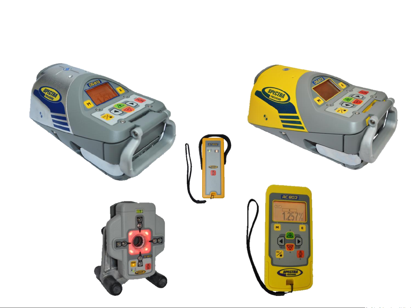
DG813
DG613
SF803
ST802
RC803
2
Page 3

TABLE OF CONTENTS
Introduction
For Your Safety
Laser
How to Use the Laser System
Powering the Laser
Turning On/Off the laser
Features and Functions
Laser Setup
Turning On/Off the laser
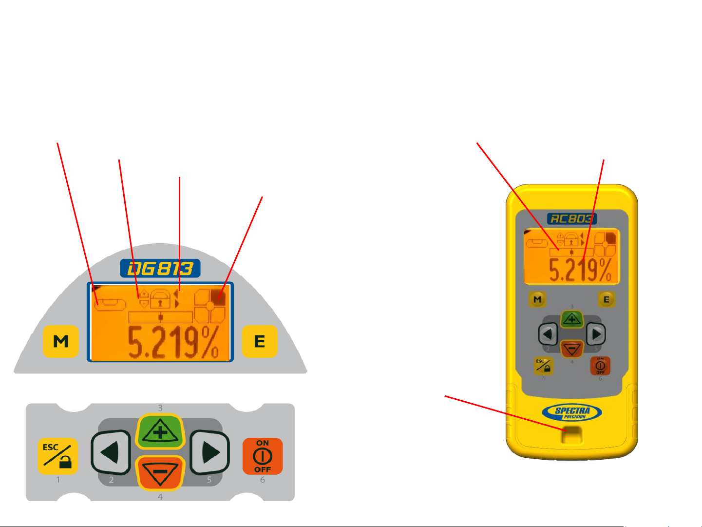
Standard Display Laser and RC803
RC803 Radio/IR Remote Control
Powering the RC803
Turning On/Off the Radio/IR Remote Control
Pairing the RC803 with the DG813/DG613
Components SpotFinder SF803
Powering the SF803
SF803 - Features and Functions
Pairing the Spot Finder SF803 with the DG813
Turning On/Off the Transporter ST802
Pairing the ST802 with the DG813/DG613
Menu Functions
Entering Grade
Automatic Spot Align (DG813)
Automatic Spot Match (DG813)
Automatic SpotLok (DG813)
Manual Spot Search (DG813)
Line Scan
Line Set/Check
Start Reference Check
Standby Mode
3
Page 4

Settings
Info
Service
Setting menu details
Grade Entry
Grade Display
Sensitivity Selection
User Name
Set Password
Password On/Off
Radio Channel
Select Language
Position Info
Calibration
PROTECTING THE UNIT
CLEANING AND MAINTENANCE
PROTECTING THE ENVIRONMENT
TECHNICAL DATA
DECLARATION OF CONFORMITY
4
Page 5
Introduction
Thank you for choosing one of the Spectra Precision Lasers from the Trimble family of precision pipe lasers.
The pipe laser is an easy-to-use tool that provides underground contractors line, elevation, and grade control
for installing storm, sanitary, or other gravity-flow pipe. This system can also be used for tunneling, boring, pipe
alignment, or any other application requiring line, elevation, and grade control.
The pipe laser projects a highly visible laser beam in a direction at a predetermined (grade) for the
alignment of gravity-flow pipe. The laser light is intercepted by a target. To align the pipe, you need to
position it so that the pipe laser’s beam is centered at the target’s bullseye.
For Your Safety
For hazardless and safe operation, read all the user guide instructions.
- Use of this product by people other than those trained on this product may result in exposure to
hazardous laser light.
- Do not remove warning labels from the unit.
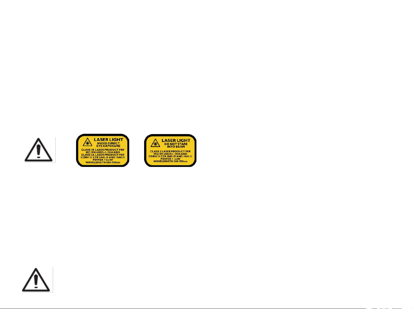
- The DG813/DG613 are class 3A/3R laser (<5mW; 600 – 680nm) IEC 60825-1:2007). Class 2 version are
also available.
- Never look into the laser beam or direct it to the eyes of other people.
- Always operate the unit in a way that prevents the beam from getting into people's eyes.
- If initial service is required, which results in the removal of the outer protective cover, removal
must only be performed by factory-trained personnel.
Caution: Use of other than the described user and calibration tools or other procedures
may result in exposure to hazardous laser light.
Caution: Using different than described at the pipe laser user guide, may result in unsafe
operation.
5
Page 6

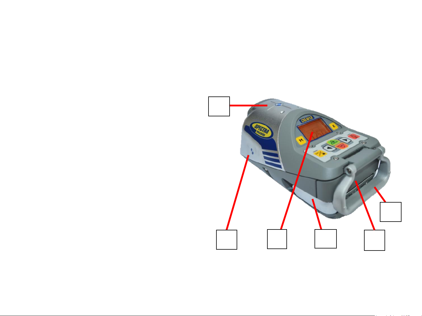
Features and Functions
Laser
1 Battery Compartment
2 Battery Door Latches
3 LCD Graphic Display
4 Grade Axis Pivot Marker
5 Line-Axis Pivot Marker and LED
6 Handle
7 Axis Alignment Markers
8 Mounts for scope adapter
9 5/8”-11 Threaded Mount
10 Remote Receiver Window
11 Beam-Exit Window
12 Power Button
13 M - Menu Button
14 E - Enter Button
15 Escape/Lock Button
16 Left Line Control Button
17 Plus Button
18 Minus Button
19 Right Line Control Button
How to Use the Laser System
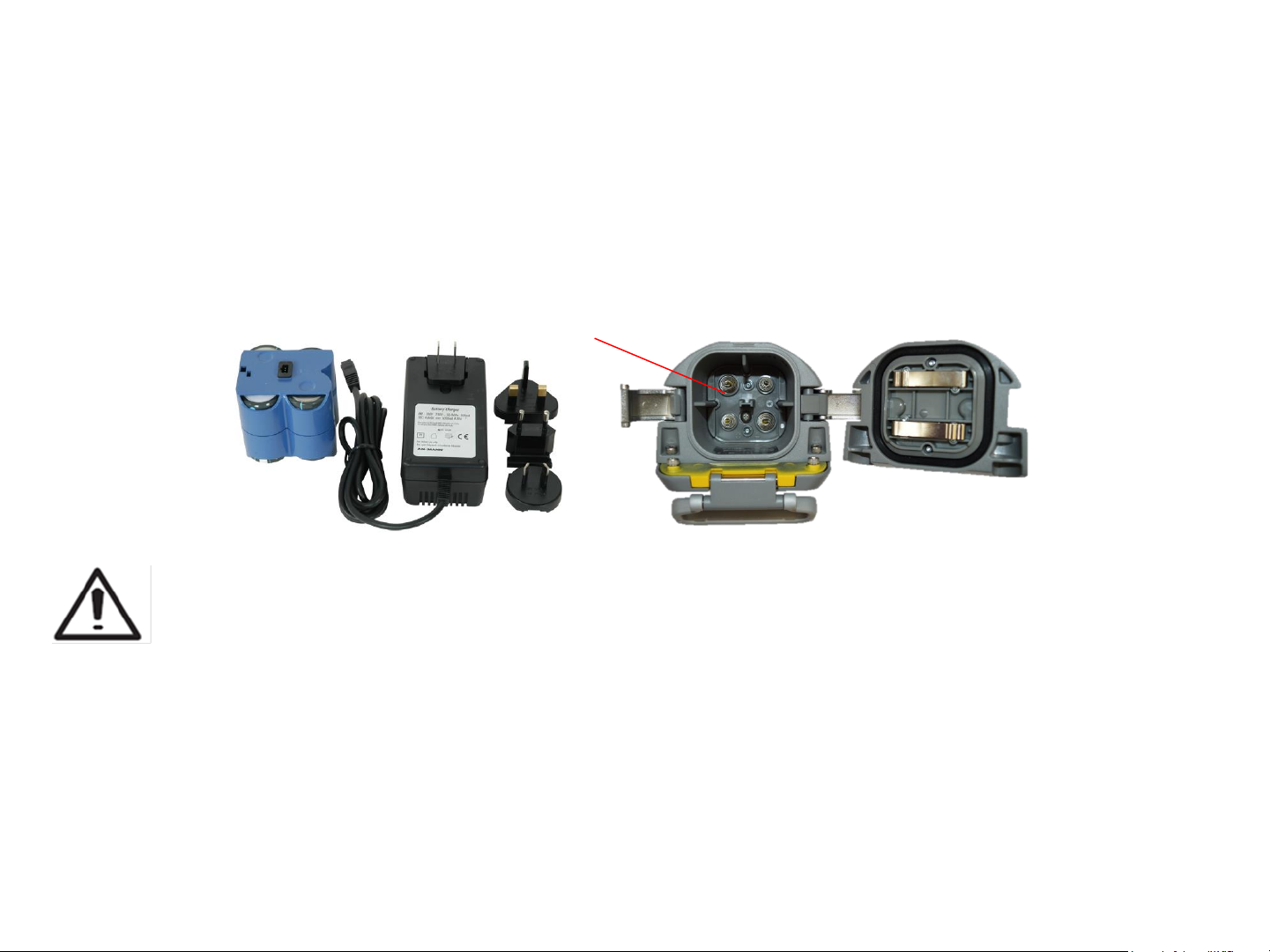
Batteries
WARNING
Ni-MH batteries may contain small amounts of harmful substances.
Be sure to charge the battery before using it for the first time, and after not using it for an extended length of
time.
Charge only with specified chargers according to device manufacturer‘s instructions.
Do not open the battery, dispose of in fire or short circuit; it may ignite, explode, leak or get hot causing
personal injury.
Dispose in accordance with all applicable federal, state, and local regulations.
Keep the battery away from children. If swallowed, do not induce vomiting. Seek medical attention
immediately.
6
Page 7
Powering the Laser
Recharging the Batteries
The laser is shipped with a rechargeable Ni-MH battery pack, it is keyed to prevent mis-insertion.
Note: The approximate charge of the batteries is shown at the top of the LCD when pressing the E button.
The charger requires approx. 10 hours to charge completely discharged batteries.
For charging, connect the plug of the charger to the recharge jack of the battery pack.
New or long-time out-of-use rechargeable batteries reach their best performance after being charged and
recharged five times. Alkaline batteries can be used as a backup. Insert 4 D-cell batteries noting the plus (+)
and minus (-) diagrams inside the battery housing.
The batteries should only be charged when the laser is between 50°F and 104° F (10°C to
40°C). Charging at a higher temperature may damage the batteries. Charging at a lower
temperature may increase the charge time and decrease the charge capacity, resulting in
loss of performance and shortened life expectancy.
Installing Batteries
Open the battery door by pulling out the door latches. Insert batteries (or a rechargeable battery pack) into the
housing so that the negative poles are on the bigger battery spiral springs.
Close the battery door and lock it by pushing the door latches back to the housing.
Only the original rechargeable battery pack allows charging with the provided charger.
7
Page 8
Features and Functions
1. Battery Compartment – holds the
NiMH battery pack. (D-Cell alkaline batteries
can be used as a backup.)
2. Battery Door Latches –
locks/unlocks and holds the battery
compartment in place.
3. LCD Graphic Display - shows the
power, grade, battery, out-of-level, beam
position and status of the laser.
4. Grade Axis Pivot Marker - identifies
the pivot point for the grade
system
5. Line-Axis Pivot Marker and LED –
used to align a transit over the top of the
laser; lights for 15 minutes after turning on
the laser or pressing one of the buttons.
6. Handle - to carry the laser easily
5
4
3
2
6
1
and to attach a safety rope in manholes
with water.
8
Page 9
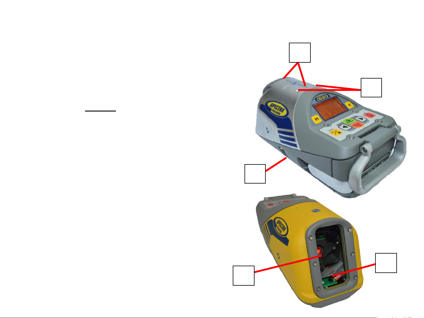
Features and Functions
7. Axis Alignment Markers - used to align
the laser when the line system is centered.
8. Mounts for scope adapter – to
attach the optional scope adapter for the
„Over the Top“ application
9. 5/8”-11 Threaded Mount – to attach the laser
to various setup accessories
10. Remote Receiver Window –
receives signals from the RC803 and SF803
11. Beam-Exit Window – provides a
7
8
9
clear window for the laser beam to exit
the pipe laser.
10
11
9
Page 10
Features and Functions
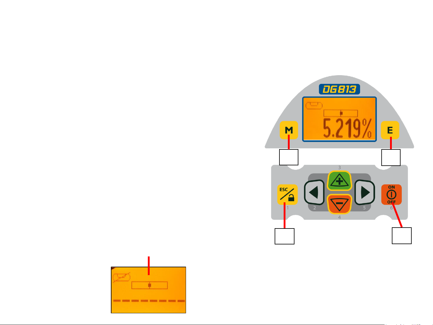
12. Power Button - turns the laser On/Off
(To turn off the laser, press and hold the button
for 2 seconds).
13. M – Menu Button - Quickly press and release
starts the menu entry. Use the 2 to 5
buttons to toggle through the menu.
14. E - Enter Button - Quickly press and release
to activate a selected menu function and show the
actual laser and remote control battery status.
15. Escape/Lock (ESC) Button - (If pressed
13
14
simultaneously with one of the left/right or +/-
buttons, it locks/unlocks the +/- or the left/right
buttons, so that the unit can’t be unintentionally
changed. If pressed for 5 seconds, the unit
switches to the manual mode (steep grade).
15
12
10
Page 11
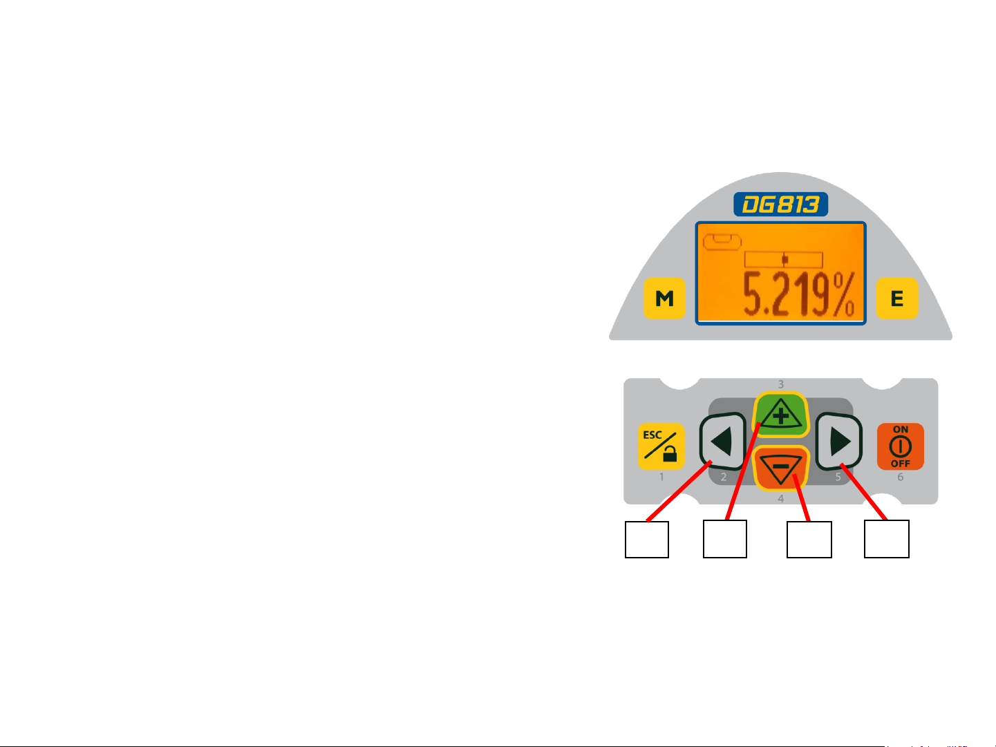
Features and Functions
16. Left Line Control Button - moves the laser
beam to the left. (Simultaneously pressed with the
Right Line Button, centers the line.)
17. Plus Button - increases the grade.
18. Minus Button - decreases the grade.
19. Right Line Control Button - moves the laser
beam to the right. (Simultaneously pressed with the
Left Line Button, centers the line.)
16
17
18
19
11
Page 12
Laser Setup
Position the laser at the manhole invert or on bottom of the trench at the desired elevation.
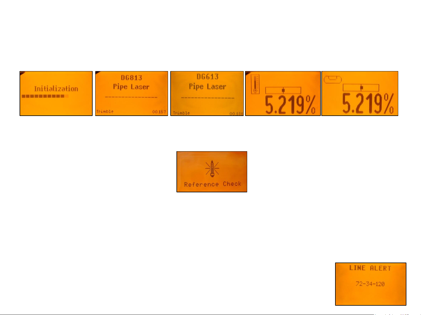
Turning On/Off the laser
Press the power button to turn On the laser; the LCD shows Initialization for one second (red and green
LEDs are on - diagnostic mode).
The unit starts the temperature/reference check while the thermometer symbol is flashing.
Don‘t start automatic functions at the menu before the reference check has been finished.
If an automatic function will be selected and then confirmed with the E button during the reference
check, the display shows the reference check is still running.
The standard display turns on and the self-leveling will start at once.
The unit is leveled when the laser beam is no longer flashing (once every second).
To turn Off the laser, press and hold the power button for two seconds.
If the laser is positioned beyond its self-leveling range of -12 to + 40%, the laser beam remains flashing.
Reposition the laser within its self-leveling range. The laser’s cross axis is completely compensated over
the entire roll range. Once leveled, the unit constantly monitors its level condition. Depending on the
selection at settings, the setup control (Line alert) is activated 5 minutes or 30 seconds after self-leveling
was performed. If Line Alert condition comes Off, the beam (+LEDs) flashes two times,
pauses for 2 seconds and flashes again two times. After deleting the Line Alert by
pressing the E button, check the beam’s correct position using the target at the last
pipe which was led before the Line alert came off.
12
12
Page 13
Features and Functions
Standard Display Laser and RC803
The remote control mirrors the functionality of the pipe laser keypad
Automatic mode Beam line position related to the housing
+/- buttons locked actual grade value
line buttons locked
Beam position at SF803
9
1 - Escape/Lock Button
2 - Left Line Control Button
3 - Plus Button
4 - Minus Button
5 - Right Line Control Button
6 - Power Button
M - Menu Button
E - Enter Button
Hole for hand loop
13
Page 14
RC803 Radio/IR Remote Control
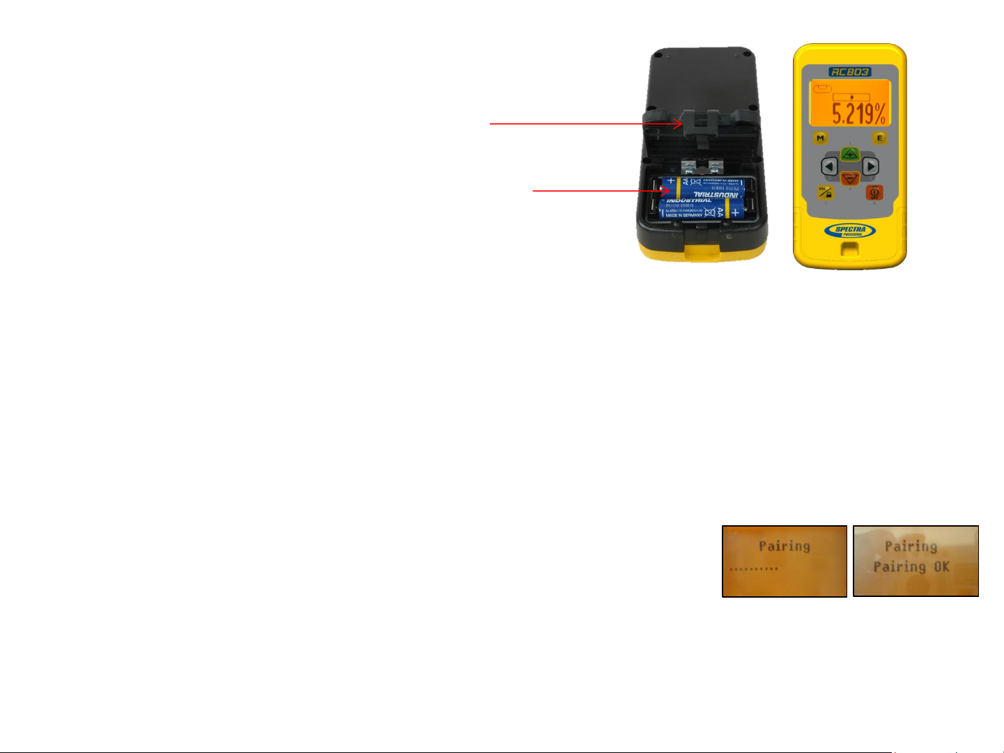
Powering the RC803
1. Open the battery door using a coin or similar pry
device to release the battery door tab on the RC803.
RC803 will be shipped with alkaline batteries
Rechargeable batteries can be used optional but need
to be charged externally
2. Insert two AA batteries noting the plus (+) and minus (-)
diagrams inside the battery housing.
3. Close the battery door. Push down until it “clicks”
into the locked position.
Turning On/Off the Radio/IR Remote Control
The Radio/IR remote control is a hand-held device that allows you to send operational commands to the laser from a
remote location.
Press the power button to turn on the radio/IR remote control.
If the RC803 is outside the radio operating range the remote switches automatically into the IR connection capability.
Note: When the remote control is initially turned on, the standard display (model number and software version) appear
for the first 3 seconds, then the grade value and line direction indications briefly appear in the LCD.
With every button press, the LCD backlight is activated and turns off automatically if no button is pressed for 8
seconds.
To turn off the radio remote control, press and hold the power button for two seconds.
Note: 5 minutes after the last button press, the remote control turns off automatically.
Pairing the RC803 with the DG813/DG613 - First, make sure the transmitter and the remote control
are turned off. Then press and hold the Escape/Lock (ESC) button and turn on the transmitter. During the next 6
seconds (the red LED flashes fast while the display shows Pairing) repeat the same steps on the remote control.
The remote’s display show Pairing OK for one second and then the same function as the laser is actually working to
indicate the transmitter has been matched with the remote control.
14
Page 15

Components Spot Finder SF803
10
1
13 12
5
9
10
7 3
6
10
5
8
11
1 - SF803
2 - Target Plate
for Spot Finder
3 - Center Hole
4 - Power Button
5 - Bubble Vial
4
6 - Battery LED
10
7 - Mode LED
8 - Red Direction LEDs
9 - IR transmitters/receivers
10 - Marking notches (front and back)
11 - M6 Clamp Mount
12 - Battery door
13 - Latch for Battery Door
14 - Release Tab Target Plate
15 – SF803-Poladapter
2
14
15
15
Page 16

Powering the SF803
1. Open the battery door pulling the battery door latch.
The SF803 will be shipped with alkaline batteries.
Rechargeable batteries can be used optional but need to be charged externally
2. Insert four AA batteries noting the plus (+) and minus (-) diagrams inside on the battery door.
3. Close the battery door. Push down until it “clicks” into the locked position.
SF803 - Features and Functions
1. Power Button:
Press and release the power button to turn ON the SF803.
All display LED’s will light for 1.0 sec.
Press and hold power button for >2 sec. to turn OFF the SF803.
LED’s:
2. LED1:
solid green when SF803 is on and battery OK
blinking red if battery voltage is 3,8V<V bat <4V
solid red if battery voltage is <3,8V; SF803 turns off automatically after 5 min.
3. Mode LED2:
yellow solid: radio connection OK / yellow flashing: none or lost radio signal
4. Direction LEDs red:
Manual mode: pointing towards the center of the plumb beam.
All 4 LEDs are solid red when the beam is centered.
Automatic SpotLok mode: LEDs solid for 5 min., then flashing every 5 seconds.
4
3
2
1
Pairing the Spot Finder SF803 with the DG813 -
First, make sure the transmitter and the Spot Finder are turned off. Then press and hold the Escape/Lock button
and turn on the transmitter. Turn On the Spot Finder; the SF803 pairs now automatically with the transmitter.
After a successful pairing, the Laser shows the standard display while the yellow SF803 LED is solid.
16
Page 17

ST802 Transporter
The Transporter is a hand-held device that extends the radio operating range between the RC803 and the DG813
(standard) and DG613 (optional).
Powering the ST802
1. Open the battery door using a coin or similar pry
device to release the battery door tab on the ST802.
ST802 will be shipped with alkaline batteries
Rechargeable batteries can be used optional but need
to be charged externally
2. Insert two AA batteries noting the plus (+) and minus (-)
diagrams inside the battery housing.
3. Close the battery door. Push down until it “clicks”
into the locked position.
Turning On/Off the Transporter
Press the power button to turn on the Transporter.
Note: When the Transporter is initially turned on, both LEDs turn on for one second (left LED red, right LED yellow –
diagnostic mode).
To turn off the Transporter, press and hold the power button for >2 seconds.
LED’s:
Left LED:
solid green when ST802 is on and battery OK
blinking red if battery voltage is >2V and <=2,4V
solid red if battery voltage is <=2V; ST802 turns off automatically after 5 min.
Right LED:
yellow solid: radio connection OK / yellow flashing: none or lost radio signal
Pairing the Transporter ST802 with the DG813 /DG613
First, make sure the transmitter and the Transporter are turned off. Then press and hold the Escape/Lock button and
turn on the transmitter. Turn On the Transporter; the ST802 pairs now automatically with the transmitter.
After a successful pairing, the Laser shows the standard display while the yellow ST802 LED is solid.
17
Page 18

Transporter ST802 – DG applications
DG813/613 at the manhole => ST802 => RC803
ST802 offers radio connection between
RC803 and DG813/613 also inside the
open trench at the end of the pipe.
DG813/613 at the tripod => ST802 => RC803
ST802 extends the radio operating range
between DG813/613 and RC803 working
at „Over the Top“ applications
>2 ft
>0.50 m
up to 100 m /330 ft
>2 ft
>0.50 m
up to 140 m/460 ft up to 120 m/400 ft
Page 19

Menu Functions
Press and release M button at the Standard Display to enter the MENU.
The menu offers always only the available features depending which pipe laser (DG813 or DG613) is
used.
The icon of the selected function will be highlighted.
A down arrow at the the right site indicates that the user can scroll down through the menu using the down
arrow button.
After going to the next menu row, an up/down arrow at the the right site indicates that the user can scroll
up/down through the menu using the +/- arrows buttons.
Pressing and releasing button M changes the unit always back to the standard or previous display.
Press and release the 2 to 5 buttons until the desired function at the selected menu row is marked.
Press and release button E to open the submenu OR start the selected function.
Menu functions available at the DG813
Menu functions available at the DG613
19
Page 20

Menu Functions (IR controlled)
If the RC803 is paired with a transmitter and the radio connection doesn’t work, e.g., through a pipe, the IR
connection offers the following functions.
Press and release the M button at the Standard Display.
Pressing and releasing button M changes the unit always back to the standard or previous display.
Press and release the buttons 2 to 5 until the desired icon is highlighted.
Press and release E button start the selected function.
Note: If a remote is paired with a transmitter the IR signals of the remote (in case of an interrupted radio
connection) will be transmitted in a private mode so that only the paired transmitter can receive these IR
commands.
IR-menu functions available at the DG813
IR-menu functions available at the DG613
20
Page 21

Entering Grade – changing the grade value in Step + Go or Digit Select mode.
Press and release the M (Menu) button; Grade Edit will be highlighted.
Press/release button E The grade value will be shown.
Press/release button M escape/return to the standard display.
Step + Go Mode:
Press and hold (+/-) buttons for changing the grade value after the comma.
Press/release button 2/5 change the sign of the grade value.
Press and hold Plus (+) and Minus (-) buttons simultaneously starts Quick change
mode where the grade value will be set to 0% and then starts changing in front of the
comma in 1% increments.
Note: When the grade value for the axis reaches its highest amount, the grade value
switches to the lowest value for that axis. For example, the value switches from +40% to
-12%.
The laser will self-level to the required grade position after confirming the grade change
with E (Enter) button.
Note: The bubble symbol at the laser’s and remote’s LCD will flash until the laser has
been self-leveled to the requested grade position.
Digit Select Mode (Default):
A cursor at the sign of the grade value is flashing.
Press and hold the ESC button quick set to 0%.
Press/release Plus (+) and Minus (-) buttons change the sign of the grade value.
Pressing and releasing right or left button moves the cursor to the right/left.
Press and release Plus (+) and Minus (-) buttons to change the selected digit.
The laser will self-level to the required grade position after confirming the grade change
with E (Enter) button.
Grade Entering can be exited any time by pressing and releasing M button.
21
Page 22

Automatic Spot Align (only DG813) - The Spot Finder SF803 guides the
beam to the target point in the horizontal axis, while the Z-axis grade value will be
maintained.
Press and release the M button at the standard display and select Spot Align using
the (+)/(-) and left/right buttons. Press/release button M escape/return to the
standard display. Pressing and releasing button E starts the
Spot Alignment function while the beam moves to the
0% position.
A Spot Finder symbol will flash while the beam becomes a
rotating fan beam which will search automatically for the
SF803‘s center position in a range up to +45°/ 100%.
Note: The SF803 needs to be tilted into the direction of the
DG813 when placed at a steep slope position.
Note: The left SF symbol flashes while an additional SF symbol at the right site of the
display indicates the beam movement until the beam is centered at the SF803.
When the alignment is finished, the beam moves plumb down to the dialed in grade value.
Automatic Spot Align can be exited any time by pressing and releasing ESC button.
22
Page 23

Automatic Spot Match (only DG813) - Automatic-Spot-Match can be used
for measuring an unknown grade value in an existing pipe or open trench.
Press and release the M button at the standard display and select Spot Match
using the (+)/(-) and left/right buttons.
Press/release button M escape/return to the standard display.
Pressing and releasing E button starts the automatic Spot Match while the beam
becomes a rotating fan beam which will be automatically aligned to the SF803‘s center position.
Note: The left SF along with a grade symbol flashes while an additional SF symbol at the right
site of the display indicates the beam movement until the beam is centered. When Spot Match
has finished, the beam goes through the SF hole and the measured grade value will be displayed.
Automatic Spot Match can be exited any time by pressing and releasing ESC button.
%?
Automatic SpotLok (only DG813) - Automatic SpotLok (like PlaneLok) can be used to align
and hold the beam automatically to the SF803’s center point in automatic or manual mode.
Z
%
Press and release the M button at the standard display and select SpotLok using
the (+)/(-) and left/right buttons.
Press/release button M escape/return to the standard display.
Pressing and releasing E button starts automatic SpotLok while the beam becomes a rotating
fan beam which will be automatically aligned to the SF803‘s center position.
Note: The left SF along with a lock symbol flashes while an additional SF symbol at the right site
of the display indicates the beam movement until the beam is centered.
Automatic SpotLok can be exited any time by pressing and releasing ESC button where the unit
switches back to automatic or manual mode.
23
Page 24

Manual Spot Search Mode (only DG813) - The Spot Search mode is used for pipe laying by
detecting the beam manually using the Spot Finder SF803 and can be activated in automatic and manual
mode.
Using the “Over the Top” application, the Spot Finder detects the fan beam while the remote control’s display
provides the information to position the pipe correctly at the required direction and elevation.
Press and release the M button at the standard display and select Spot Search using the (+)/(-) and left/right
buttons.
Press/release button M escape/return to the standard display.
Pressing and releasing E button starts the manual Spot Search mode while the beam becomes a rotating fan
beam.
The empty SF symbol indicates the Spot Search mode has been activated.
A black block at the SF symbol indicates the beam position at the Spot finder and gives the direction for
finding the center of the beam. Two black blocks on top or the bottom of the SF symbol confirm the correct
direction.
4 black blocks at the SF symbol confirm the Spot Finder has been adjusted to the center of the beam which
means the pipe is placed correctly.
Manual Spot Search can be exited any time
by pressing and releasing ESC button.
24
Page 25

Line Scan - For a faster second day setup, line scan enables complete
automatically movement of the laser beam to the left and right limits.
Press and release the M button at the standard display and select
Line Scan using the (+)/(-) and left/right buttons.
Press/release button M escape/return to the standard display.
Pressing and releasing E button activates the Line Scan mode while the laser beam moves
to the right/left limits of the horizontal axis (short beep) and stops at the center position.
When the beam crosses the target press the ESC button to stop the automatic beam
movement.
Corrections for centering the beam at the target can be done using the left/right buttons.
Line Set/Check - Moves the laser beam vertically plumb to its maximum limit for setting
line in a first day setup without a SF803.
Press and release the M button at the standard display and select Line Set/Check using
the (+)/(-) and left/right buttons.
Press/release ESC button escape/return to the standard display.
Pressing and releasing E button starts the Line Set/Check mode.
The beam moves to the 0% position while the flashing Line Set/Check symbol appears.
The Line Set/Check symbol stops flashing when the beam starts moving vertical
automatically up to 45°/ 100%.
Using the + or - button at the RC803 remote control or at the laser stops the automatic
upwards beam movement. Adjust the beam using Left/Right buttons until the beam is
centered at the line stake. After aligning the beam to the required direction position,
pressing and releasing the E button starts the beam plumb down movement to the
previous dialed in grade value.
Line Set/Check can be exited any time by pressing and releasing ESC button.
25
Page 26

Start Reference Check – Before starting some sensitive pipe work, an
additional Reference Check can be started manually.
Press and release the M button at the standard display and select Reference Check
using the (+)/(-) and left/right buttons.
Press/release button M escape/return to the standard display.
Pressing and releasing E button starts the Reference Check considering the current
temperature inside the housing. While the unit checks the correct 0% reference the
beam flashes once a second simultaneously with a thermometer symbol at the display.
Standby Mode – activating/deactivating the Standby Mode.
Press and release the M button at the standard display and select Standby using the
(+)/(-) and left/right buttons.
Press/release M button escape/return to the standard display.
Pressing and releasing E button activates the Standby mode.
The self-leveling will be stopped and the beam will be turned off while the Line alert is
still active. The display shows the Standby symbol.
To deactivate Standby mode and restore full operation of the laser, press and release
E button again.
26
Page 27

Settings – offers the different setting features.
Please see the Setting Menu details at the following pages.
Info - The DG/RC information (software version, ID, etc.) or the runtime of the DG will be
displayed.
Press and release the M button at the standard display and select Info using the (+)/(-)
and left/right buttons. Press/release button M escape/return to the standard display.
Pressing and releasing E button opens the Info’s submenu. Left/Right buttons can be
used to toggle between About Laser, Runtime and Radio.
Press and release E to show the Laser (Serial number, Software version, internal
temperature, bubble vial), Runtime (endless counter) or Radio (actual radio channel)
information.
Note: The bubble vial appears after the reference check has been completed and can be
used by technicians for specific tests.
Service – ability to recalibrate level sensors.
Press and release the M button at the standard display and select Service using the
(+)/(-) and left/right buttons.
Press/release button M escape/return to the standard display.
Pressing and releasing E button starts the Z-axis calibration process
at 0%.
The Service submenu offers also access to special features for technicians only.
27
Page 28

Setting Menu Details – offers the different setting features.
Press and release the M button at the standard display and select Settings using the
(+)/(-) and left/right buttons.
Press/release M button escape/return to the standard display.
Pressing and releasing E button opens the Setting’s menu.
(+) / (-) and left/right buttons can be used to select the desired Setting function then press
button E to open the selected submenu.
Grade Entry – offers selection of Step + Go or Digit Select Mode.
Press and release left/right buttons until Grade Entry is displayed.
Press/release M button escape/return to the main menu.
Pressing and releasing E button opens the submenu. Use the left/right buttons
to toggle between Step + Go and Digits Select. (Default).
Press and release E to confirm the selection.
Grade Display – offers the different Grade Display options.
Press and release left/right buttons until Grade Display will appear.
Press/release M button escape/return to the main menu.
Pressing and releasing E button opens the submenu. Left/right buttons can be
used to toggle between Percent (Default), Per Mille and Degree.
Press the E button to confirm the selection.
28
Page 29

Sensitivity Selection – offers three different sensitivity options.
Press and release left/right buttons until Sensitivity is displayed.
Press/release M button escape/return to the main menu.
Pressing and releasing E button opens the submenu.
Use the left/right buttons to toggle between Low, Mid (Default) and High.
Press the E button to confirm the selection.
Line Alert– offers three different Line Alert options.
Press and release (+)/(-) and left/right buttons until Line Alert is displayed.
Press/release M button escape/return to the main menu.
Pressing and releasing E button opens the submenu.
Use the left/right buttons to toggle between LA 5 min, LA 30 sec and LA Off.
Press the E button to confirm the selection.
29
Page 30

User Name – offers the activation of the user name.
Press and release (+)/(-) and left/right buttons until User Name is displayed.
Press/release M button escape/return to the main menu.
Pressing and releasing E button opens the submenu; cursor flashes.
Use the ESC button to toggle between both lines.
Pressing and releasing button right or left moves the cursor to the right/left.
Press and release buttons (+) and (-) to change the character (letters and numbers).
If the button is hold for a longer period of time, the speed of changing the characters is
increased.
Press the E button to store the user name.
Set Password – a password can be entered.
Press and release (+)/(-) and left/right buttons until Set Password is displayed.
Press/release M button escape/return to the main menu.
Pressing and releasing E button opens the submenu.
Use button 1 to 6 to type in a password at the second row containing of 4 digits and
repeat the password at the third row.
A previous used password needs to be typed in at the row “Old”.
Press and release E button to store the selected password; unit falls back to the
standard display.
30
Page 31

Password ON/OFF – activating/deactivating Password function.
Press and release (+)/(-) and left/right buttons until Password On/Off is displayed.
Press/release M button escape/return to the main menu.
Pressing and releasing E button opens the submenu.
Use the left/right buttons to toggle between Password On and Password Off.
Press the E button to confirm the selection.
Any time when the DG will be turned on, the password has to be entered after the password
function has been confirmed. Typing in a wrong password turns off the DG immediately.
Radio Channel – offers the selection of different radio channels.
Press and release (+)/(-) and left/right buttons at the Laser until RF Channel
is displayed.
Press/release M button escape/return to the main menu.
Pressing and releasing E button opens the submenu.
Use the (+)/(-) and left/right buttons to toggle between Channel k1 and Channel k6
Press the E button to confirm the selection.
After changing the radio channel, the RC803
and SF803 (only DG813) need to be paired again.
31
Page 32

Select Language – offers language selection for main menu text.
Press and release (+)/(-) and left/right buttons until Language is displayed.
Press/release M button escape/return to the main menu.
Pressing and releasing E button opens the submenu.
Use the (+)/(-) and left/right buttons to toggle between the different language options.
Press the E button to confirm the selection.
Position Info – capability of changing transmitters geographical location
Press and release (+)/(-) and left/right buttons until Position Info is displayed.
Press/release M button escape/return to the main menu.
Pressing and releasing E button opens the submenu; cursor flashes.
Pressing and releasing right or left button moves the cursor to the right/left.
Use the ESC button to toggle between Latitude and Altitude.
Use the (+) and (-) buttons for editing the required numbers, then press the E button to
confirm the dialed in numbers.
32
Page 33

Error
codes
Description
Solution
21
Temporary EEprom problem
Repeat pairing and re
120
LA
Check laser beam
130
Mechanical Limit during
nly at
DG813
Re
existing slope is
140
Laser beam blocked
Make sure there are no obstacles between the
transmitter and the
141
Time Out
leveling could
allowed
Check radio operating range/ connection; ensure a
stable
Troubleshooting DG813/DG613
Any error message can be deleted with a short press of the E button. The table shows the related description and
possible solutions.
The next service center should be contacted if a different error message as shown at the table will be displayed.
alert - Unit setup has been changed
Spot Match - o
- only at DG813
– Automatic alignment or self-
not be completed in the
time
-enter the customer settings
elevation/direction
-align the closer to the alignment point; check if
below/above -12% to +40%
SF803
laser setup
33
Page 34

Calibration
Checking Calibration
34
Page 35

Checking the calibration of your pipe laser is easy. All you need is an engineer’s rule and your pipe
Point A
Point B
Second Reading
A2 B2
First Reading
A1 B1
Difference
A2
B2
Error in 100 feet (30 m)
laser.
1. Select a level road, packing lot or field whose rise is not more than 4 inches in 100 feet
(10 cm/30 m).
2. Choose two points (A and B) about 100 feet (30 m) apart. The distance doesn’t have to be
measured, but the points must be found, so mark them well.
3. Set up the pipe laser just behind the lowest point and rough level.
4. Turn on the pipe laser and let it warm up for about 10 minutes.
5. Set the grade counter to 0.000%.
6. Aim the laser beam so that it passes over points A and B. Allow the pipe laser to self-level.
7. Accurately measure the elevation to the center of the beam at point A and record the elevation
as A1 in a table like the one shown below.
- A1
- B1
(A2 - A1) – (B2 - B1)
2
35
Page 36

8. Accurately measure the elevation to the center of the beam at point B and record the elevation
as B1.
9. Move the pipe laser behind point B and aim the laser beam so that it passes over points A and B.
Allow the pipe laser to self-level.
10. Accurately measure the elevation to the center of the beam at point B and record the elevation
as B2.
11. Accurately measure the elevation to the center of the beam at point A and record the elevation
as A2.
12. Subtract the A1 and B1 elevation readings from A2 and B2 elevation readings.
Note: Your laser is in calibration if the difference between A2 – A1 equals B2 – B1.
Note: If A2 – A1 is greater than B2 – B1, the laser beam is shooting high and you should readjust the
laser’s calibration bringing the beam to level.
Note: If A2 – A1 is less than B2 – B1, the laser beam is shooting low and you should readjust the
laser’s calibration bringing the beam to level.
Note: If the error is greater than 0.02 feet in 100 feet (6.4 mm/30 m), return the pipe laser to an
authorized Trimble service center.
36
Page 37

Grade Check
After the first 25 – 50 feet (8 – 15 m) of pipe has been laid, it is recommended that you make a
grade check to insure that the setup is correct, and that the system is properly operating.
The illustration shows a method for checking grade.
1. Using a transit level, or an automatic level and a grade rod, take a reading at the beginning of
the pipe “A”.
2. Using the same instruments, obtain a level reading at the end of the pipe “B”.
3. The difference between the readings equals the rise over the run.
4. In terms of % of grade, rise divided by the run times 100 equals the percent of grade.
Note: The user of this equipment is expected to follow all operating instructions and make
periodic checks on the proper grade, elevation, and line of the pipe as it is being laid. Trimble or
its representatives assumes no responsibility for improperly laid pipe.
37
Page 38

Example:
Feet / Tenths
Metric
Rod Reading at “A”
15.74 feet
4.801 m
Rod Reading at “B”
12.289 feet
3.749 m
Rise or Difference (A
3.451 feet
1.052 m
Distance from A to B
145 feet
44.196 m
Rise divided by Run
0.0238
0.0238
Rise divided by Run times 100
= Laser Setting
2.38%
2.38%
Rise according to engineering
plans
(2.38% * 145 feet)
= 3.451 feet
(2.38% * 44.196 m)
= 1.052 m
– B)
The pipe is laid correctly when the rod reading “A” minus rod reading “B” equals the rise
according to the engineering plans.
38
Page 39

PROTECTING THE UNIT
Do not expose the unit to extreme temperatures or temperature changes (do not leave inside the car).
The unit is very robust and can resist damage if dropped even from tripod height. Before continuing your
work, always check the leveling accuracy. See Checking Calibration section.
The laser is water proof and can be used indoors and outdoors.
CLEANING AND MAINTENANCE
Dirt and water on the glass parts of laser or prism will influence beam quality and operating range
considerably.
Clean with cotton swabs.
Remove dirt on the housing with a lint-free, warm, wet and smooth cloth. Do not use harsh cleansers or
solvents.
Allow the unit to air dry after cleaning it.
PROTECTING THE ENVIRONMENT
The unit, accessories and packaging ought to be recycled.
This manual is made of non-chlorine recycling paper.
All plastic parts are marked for recycling according to material type.
Do not throw used batteries into the garbage, water or fire. Remove them in compliance
with environmental requirements.
Notice to Our European Union Customers
For product recycling instructions and more information, please go to:
www.trimble.com/environment/summary.html
Recycling in Europe: To recycle Trimble WEEE,
Call +31 497 53 2430, and ask for the “WEEE Associate”
Or
Mail a request for recycling instructions to:
Trimble Europe BV
c/o Menlo Worldwide Logistics
Meerheide 45
5521 DZ Eersel, NL
39
Page 40

Warranty
Trimble warrants the DG813/DG613 to be free of defects in material and workmanship for a period of five
years. Trimble or its authorized service center will repair or replace, at its option, any defective part, or the
entire product, for which notice has been given during the warranty period. If required, travel and per diem
expenses to and from the place where repairs are made will be charged to the customer at the prevailing
rates. Customers should send the product to Trimble Navigation Ltd. or the nearest authorized service
center for warranty repairs or exchange, freight prepaid. Any evidence of negligent, abnormal use,
accident, or any attempt to repair the product by other than factory-authorized personnel using Trimble
certified or recommended parts, automatically voids the warranty. Special precautions have been taken to
ensure the calibration of the laser; however, calibration is not covered by this warranty. Maintenance of the
calibration is the responsibility of the user.
The foregoing states the entire liability of Trimble regarding the purchase and use of its equipment. Trimble
will not be held responsible for any consequential loss or damage of any kind. This warranty is in lieu of all
other warranties, except as set forth above, including any implied warranty merchantability of fitness for a
particular purpose, are hereby disclaimed. This warranty is in lieu of all other warranties, expressed or
implied.
40
Page 41

TECHNICAL DATA
Laser
Accuracy, Self-Leveling (level)
1,2
Operational area
: up to 150 m (500 feet)
Laser type: red diode laser 600 - 680 nm
Laser class : Class 3A/3R, <5mW OR class 2
Self-leveling range: Longitudinal: Over the entire grade range with
automatic cross axis compensation
(no rough leveling required);
Grade range: -12% to +40%
Spot Align search range (DG813): up to +45° (with SF803 tilted to the laser)
Line Range: 20° ±1°
Leveling indicators: LCD indications; beam and LED flash
Power source: 10000mAh NiMH battery pack
Battery life1: 40 hours NiMH; 50 hours alkaline
Temperature compensation: Yes
Operating temp.: -20°C to 50°C (-4°F to 122°F)
Storage temp.: -20°C to 70°C (-4°F to 158°F)
Tripod attachments: 5/8 x 11 horizontally
Dust and Water proof: IP67
Weight: 3.98 kg (6.61 lbs)
Low voltage indication: LCD battery indicator
Low voltage disconnection: unit shuts off
1) at 21° Celsius
2) under optimal atmospheric circumstances
3) along the axis
1,3
: ± 1.5 mm/30 m, 1/16“ @ 100 ft, 10 arc seconds
41
Page 42

TECHNICAL DATA
Remote Control RC803
Radio operating range (Over the Top)
IR operating range (front)
1,4
: up to 150 m (500 ft)
Power source: 2 x 1.5V AA alkaline batteries
Battery life1: 130 hours
Dust and Water proof: IP66
Weight (incl. Batteries): 0.26 kg (0.57 lbs)
Spot Finder SF803
Operating range
1,4
: 5 m (16 ft) up to 150 m (500 ft)
Power source: 4 x 1.5V AA alkaline batteries
Battery life1: 30 hours
Dust and Water proof: IP67
Weight (incl. Batteries and slider): 0.43 kg (0.95 lbs)
Transporter ST802
Radio operating range : up to 100 m (330ft)
Power source: 2 x 1.5V AA alkaline batteries
Battery life1: 24 hours (continuously use)
Dust and Water proof: IP66
Weight (incl. Batteries): 0.3 kg (0.75 lbs)
1) at 21° Celsius
3) along the axis
4) depending on WIFI/WLAN ambient environment
1,3
: up to 130 m (425 ft)
42
Page 43

DECLARATION OF CONFORMITY
Please disregard the declaration of conformity within the manual.
Following is the valid declaration:
We
Trimble Kaiserslautern GmbH
Declare under our sole responsibility that the products
DG813/DG613 and RC803; SF803; ST802
To which this declaration relates is in conformity with the following directives:
RoHS 2011/65/EU, R&TTE 1995/5/EC
Relevant harmonized standards:
EN 60825-1:2014, EN 60950-1:2006 + Amdts, ETSI EN 301 489-01 V1.9.2, ETSI EN 301 489-17 V2.2.1
The managing director
Electro-Magnetic Compatibility
Declaration of Conformity
This digital apparatus does not exceed the Class B Limits for radio noise for digital apparatus set out in the
Radio Interference Regulations of the Canadian Department of Communications.
This device complies with part 15 off the FCC rules. Operation is subject to the condition that this device does
not cause harmful interference.
Note: The product has been tested and found to comply with the limits for a Class B digital device, pursuant
to part 15 of the FCC rules. These limits are designed to provide reasonable protection against harmful
interference in a residential installation. The product generates, uses and can radiate radio frequency energy
and, if not installed and used in accordance with the instructions, may cause harmful interference to radio or
television reception, which can be determined by turning the product off and on. The user is encouraged to try
to eliminate the interference by one or more of the following measures:
• Reorient or relocate the receiving antenna.
• Increase the separation between the product and the receiver.
• For more information, consult your dealer or an experienced radio/television technician.
Caution: Changes or modifications to the product that are not expressly approved by Trimble could void
authority to use the equipment.
43
Page 44

FCC / IC
General information
IC 4131A-TK46BL
FCC ID PWR-TK46BL
Contains IC: 4131A-TK42RF
Contains FCC ID: PWR-TK42RF
This device complies with Industry Canada licence-exempt RSS standard(s).
Operation is subject to the following two conditions:
(1) this device may not cause interference, and
(2) this device must accept any interference, including
interference that may cause undesired operation of the device.
Le présent appareil est conforme aux CNR d'Industrie Canada applicables aux appareils radio exempts de
licence.
L'exploitation est autorisée aux deux conditions suivantes :
(1) l'appareil ne doit pas produire de brouillage, et
(2) l'utilisateur de l'appareil doit accepter tout brouillage radioélectrique subi, même si le brouillage est
susceptible d'en compromettre le fonctionnement.
Compliance level CAN ICES-3 (B) / NMB-3 (B)
44
Page 45

FCC Compliance Statement:
FCC Compliance Statement
Changes or modifications not expressly approved by the party responsible for compliance could void
the user's authority to operate the equipment.
This device complies with Part 15 of the FCC rules.
Operation is subject to the following two conditions:
(1) This device may not cause harmful interference, and
(2) this device must accept any interference received, including interference that may cause undesired
operation.
Section 15.21 Information to user changes or modifications not expressly approved by the party responsible
for compliance could void the user's authority to operate the equipment.
Section 15.105 (a)
NOTE: This equipment has been tested and found to comply with the limits for a Class A digital device,
pursuant to part 15 of the FCC Rules. These limits are designed to provide reasonable protection against
harmful interference when the equipment is operated in a commercial environment.
This equipment generates, uses, and can radiate radio frequency energy and, if not installed and used in
accordance with the instruction manual, may cause harmful interference to radio communications.
Operation of this equipment in a residential area is likely to cause harmful interference in which case the
user will be required to correct the interference at his own expense.
45
Page 46

 Loading...