

Page 1

Network Camera Web Setup Manual
Version 1.0
i
Page 2

Table of Contents
1 Connection and Login .................................................................................................................... 1
1.1
Network Connection ........................................................................................................ 1
1.2
Log in ................................................................................................................................ 1
2 Live View ........................................................................................................................................ 3
2.1
Stream Setup ................................................................................................................... 3
2.2
Function Menu................................................................................................................. 4
2.3
Live View Display Adjustment ......................................................................................... 5
2.3.1 Image Adjustment .................................................................................................... 5
2.3.2 Original Size .............................................................................................................. 6
2.3.3 Full Screen ................................................................................................................. 6
2.3.4 Width and Height Ratio ............................................................................................ 6
2.3.5 Fluency Adjustment .................................................................................................. 6
2.3.6 Rules Info .................................................................................................................. 6
2.3.7 Zoom and Focus ........................................................................................................ 6
2.4
Fisheye Live View ............................................................................................................. 8
3 PTZ Control .................................................................................................................................... 9
3.1
Scan/Tour/Pattern/Pan ................................................................................................. 10
3.2
Preset ............................................................................................................................. 10
3.3
Go To .............................................................................................................................. 11
4 Playback ....................................................................................................................................... 12
4.1
Playback ......................................................................................................................... 12
4.1.1 Play Controls ........................................................................................................... 13
4.1.2 Playback File ........................................................................................................... 14
4.1.3 Playback Cut............................................................................................................ 16
4.1.4 Record Type ............................................................................................................ 16
4.1.5 Progress Bar ............................................................................................................ 16
4.1.6 Assistant Function................................................................................................... 17
4.1.7 Image Playback ....................................................................................................... 17
5 Setup ............................................................................................................................................ 18
5.1
Basic Setup ..................................................................................................................... 18
5.1.1 Image Setup ............................................................................................................ 18
5.1.2 Video Setup ............................................................................................................. 29
5.1.3 Audio ....................................................................................................................... 33
5.2
Network Setup ............................................................................................................... 34
5.2.1 IP Address Setup ..................................................................................................... 34
5.2.2 Connection .............................................................................................................. 35
5.2.3 PPPoE ...................................................................................................................... 36
ii
Page 3

5.2.4 DDNS Client ............................................................................................................. 37
5.2.5 IP Filtering ............................................................................................................... 37
5.2.6 SMTP (Email) ........................................................................................................... 38
5.2.7 UPnP ....................................................................................................................... 39
5.2.8 SNMP ...................................................................................................................... 40
5.2.9 Multicast ................................................................................................................. 42
5.3
5.2.10
5.2.11
5.2.12
802.1x .............................................................................................................. 43
QoS ................................................................................................................... 43
HTTPs ............................................................................................................... 44
Event Setup .................................................................................................................... 53
5.3.1 Video detection ...................................................................................................... 53
5.3.2 Audio Detection ...................................................................................................... 56
5.3.3 Smart Plan ............................................................................................................... 59
5.3.4 Intelligent Video ..................................................................................................... 59
5.3.5 Face Detection ........................................................................................................ 65
5.3.6 Heat Map ................................................................................................................ 66
5.3.7 Alarm....................................................................................................................... 69
5.3.8 Abnormality ............................................................................................................ 69
5.4
Storage Management .................................................................................................... 72
5.4.1 Schedule.................................................................................................................. 72
5.4.2 Destination ............................................................................................................. 74
5.4.3 Record control ........................................................................................................ 77
5.5
System............................................................................................................................ 78
5.5.1 General ................................................................................................................... 78
5.5.2 User Admin ............................................................................................................. 80
5.5.3 Factory Default ....................................................................................................... 83
5.5.4 Import/Export ......................................................................................................... 83
5.5.5 Upgrade .................................................................................................................. 84
5.6
Information .................................................................................................................... 85
5.6.1 Version .................................................................................................................... 85
5.6.2 Log ........................................................................................................................... 85
5.6.3 Online User ............................................................................................................. 86
iii
Page 4

Note
The instructions in this manual apply to the following models.
• O2PH2
• O3VLD1
• O3VLB3
• O3VFDM
• O3VFBM
• O4D1
• O4B7
• O4D2M
• O4B2M
• O6MDP2
• O8D2M
• O8B2M
• O2P4X
• O2P12X
• O4P30X
iv
Page 5
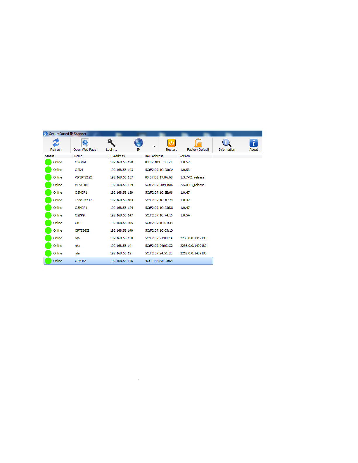
1 Connection and Login
Connect the camera to a network and run the IP Scanner tool. IP Scanner can search for the device on the local
The camera is set to DHCP mode by default.
In the device list, you can view the IP address, model number, and MAC ad
of each device. Select the applicable device and double click to open up the web viewer.
and input network camera address in the address bar or double click the
If it’s the first time accessing the camera, the browser may request to install the Active
iew live video in the browser. Go ahead and follow the steps to install the plug
The login interface is shown as below. See
Please input your user name and password.
and password is
purposes, please change the password after initial login.
X plug
1.1 Network Connection
network.
Open up IP Scanner.
See Figure 1- 1.
dress
1.2 Log in
Open Internet Explorer
device in IP Scanner.
to v
Default user name is admin
Note: For security
Figure 1- 1
Figure 1-2.
1234.
-
-in. This is required
-in.
1
Page 6
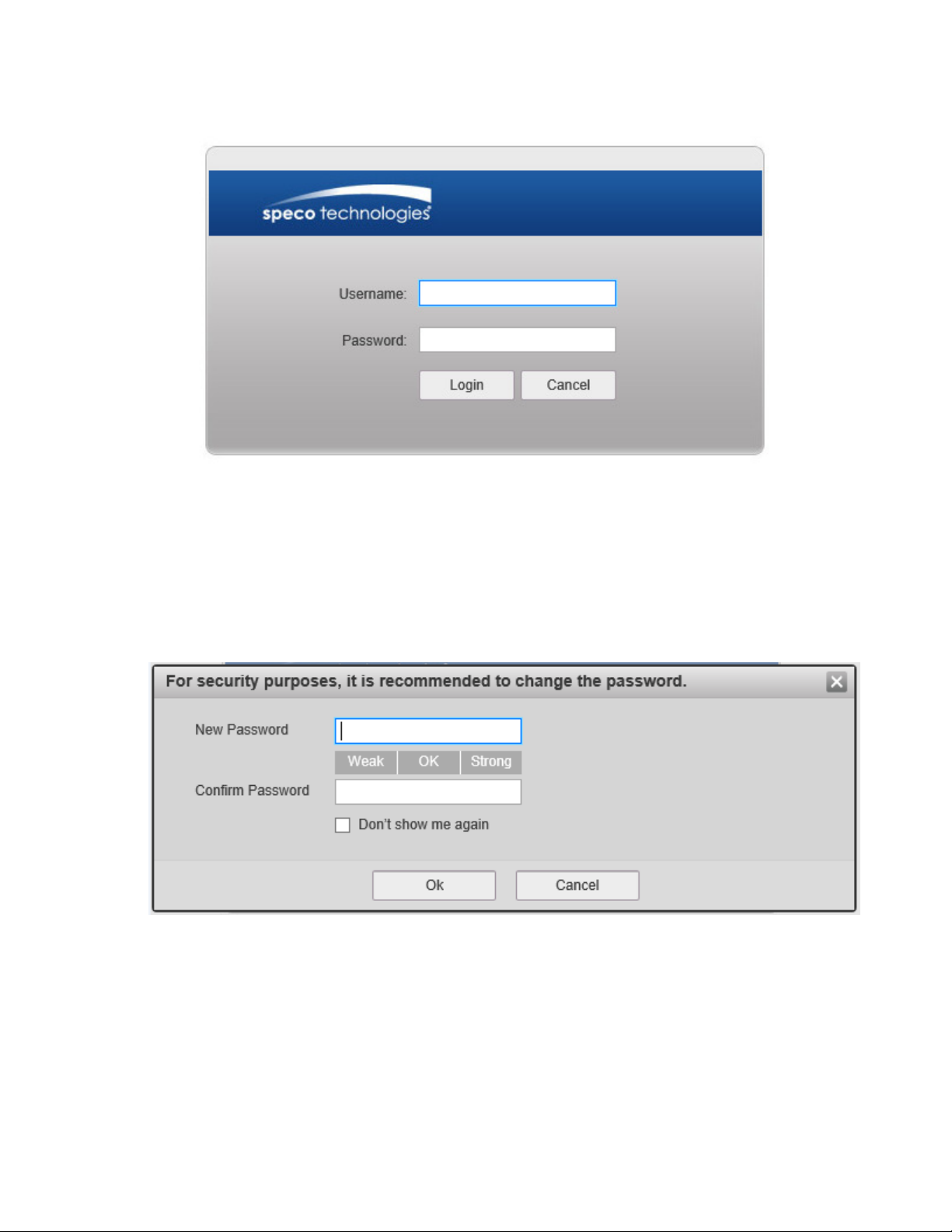
Figure 1-2
There will be a prompt shown to recommend changing the default password. For direct connection installations
on Speco’s plug and play NVRs with built-in PoE ports, please leave the password as default. For other
installations, it is highly recommended to change the password for security purposes.
Figure 1-3
2
Page 7
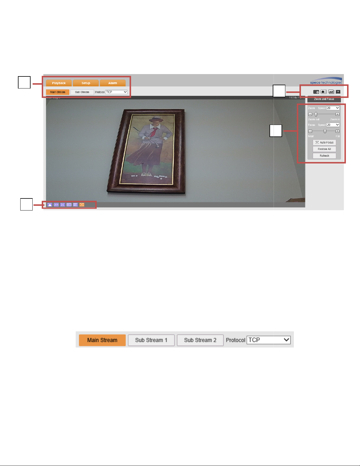
2 Live View
After logging in, the live view screen will be shown
and stream selection
menu (snapshot, digital zoom, etc)
PTZ and zoom control menu (optional)
Live view display adjustment controls
models do not have a second sub stream (Sub Stream 2)
Figure 2
1
4
2
3
. See Figure 2-1.
There are four sections:
Section 1: System menu
Section 2: Function
Section 3:
Section 4:
2.1 Stream Setup
Note: Some
The setup interface is shown in
Figure 2-1
.
-2.
Figure 2-2
3
Page 8
Please refer to the following table
for detailed information.
Function
Click it to enable main stream video monitoring and click again to
disable it
Click it to enable Sub Stream1 video monitoring and click again to
disable it
Click it to enable Sub Stream 2 video monitoring and click again to
disable it.
You can select
There are three options: TCP/UDP/Multicast
TCP is the default.
in
for detailed information.
Function
I
f there
Click on the button to force alarm to be on or off.
Click on the button to
path that’s defined in setup
Click
image per second.
1
the
stream
ing protocol from the dropdown list.
is
alarm output, status description is as follows:
Click to enable digital zoom.
click and drag to define a zone. Within the digitally
zoomed image, drag the mouse for digital pan/tilt function.
Scroll button on the mouse can also be used for digital zoom.
take a snapshot. Image will be saved to the
on the button to take 3 snapshots. Images will be taken at one
8
Parameter
Main stream
Sub Stream 1
Sub Stream 2
Protocol
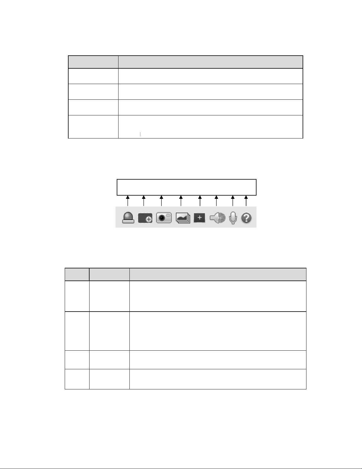
2.2 Function Menu
The function menu interface is shown
.
.
Figure 2-3.
2 3 4 5 6 7
Please refer to the following table
Parameter
1 Relay-out
2 Digital Zoom
3 Snapshot
4 Triple
Snapshot
Figure 2-3
Red: means there is alarm output.
Grey: means alarm has finished.
Left-
Right-click to return to the original image.
4
Page 9
5 Easy focus
Displays two parameters for focusing
AF Peak:
AF Max:
The close
focus effect is.
Toggle audio
Toggle push to talk
Opens the help window
Live View Display Adjustment
.
the image control interface
AF Peak and AF Max.
the video definition during the focus process.
, the better the
.
7 Audio
:
Displays
optimal value for video definition.
r AF Peak and AF Max are to each other
8 Talk
9 Help
2.3
The interface is shown as in Figure 2-4
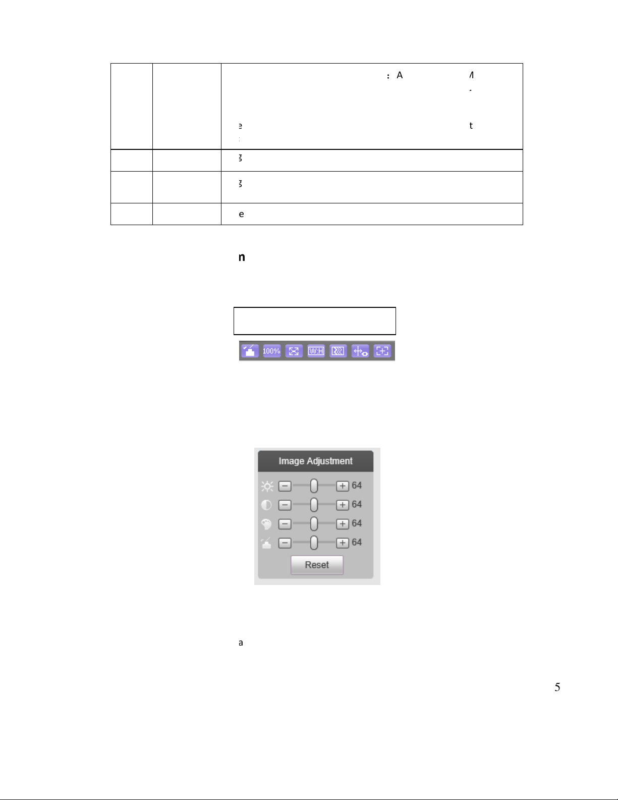
2.3.1 Image Adjustment
See Figure 2-5 for image adjustment.
.
.
1 2 3 4 5 6 7
Figure 2-4
Click the button to display/hide
Figure 2-5
on the top right pane.
5
Page 10
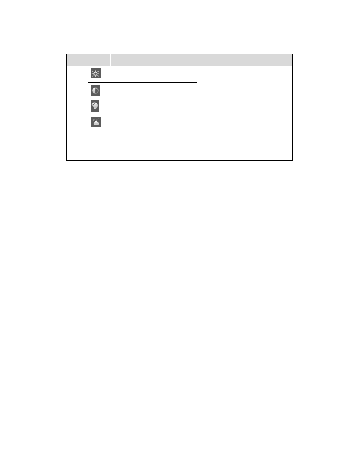
Please refer to the following table for detailed information.
Parameter Function
Video
setup
Reset Restore to system default setup.
Brightness
Contrast
Hue
Saturation
Note:
All operations here apply to
web live view only.
Please go to Setup -> Basic
Setup -> Image Setup to adjust
the parameters on the camera
itself.
2.3.2 Original Size
Click this button to display the actual resolution size of the stream.
2.3.3 Full Screen
Click to go to full-screen mode. Double click the mouse or press the Esc button on the keyboard to exit full
screen.
2.3.4 Width and Height Ratio
Click to display in the original ratio or fill the display window.
2.3.5 Fluency Adjustment
Depending on the network bandwidth, priority could be given to how the stream is delivered. The fluency mode
prioritizes the video quality over time lag. The realtime mode prioritizes real-time streaming over video quality
so it will try to minimize network lag as much as possible. Normal mode is balanced and is the default mode.
2.3.6 Rules Info
Displays any rule that has been set for analytics.
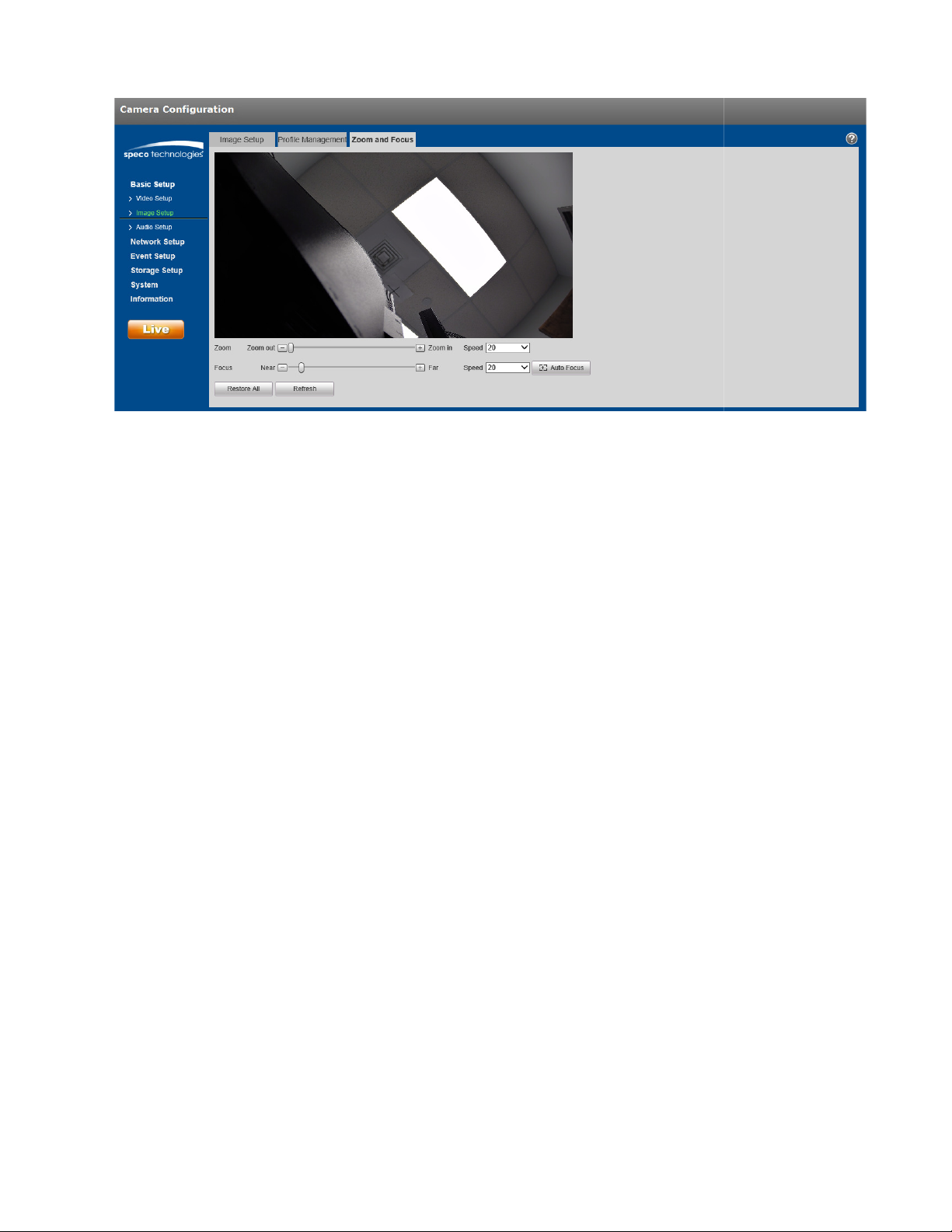
2.3.7 Zoom and Focus
Click to display the interface shown in Figure 2-6. Focus is triggered by zoom and will adjust automatically. The
focus can be adjusted manually as well or with the Auto Focus function.
6
Page 11
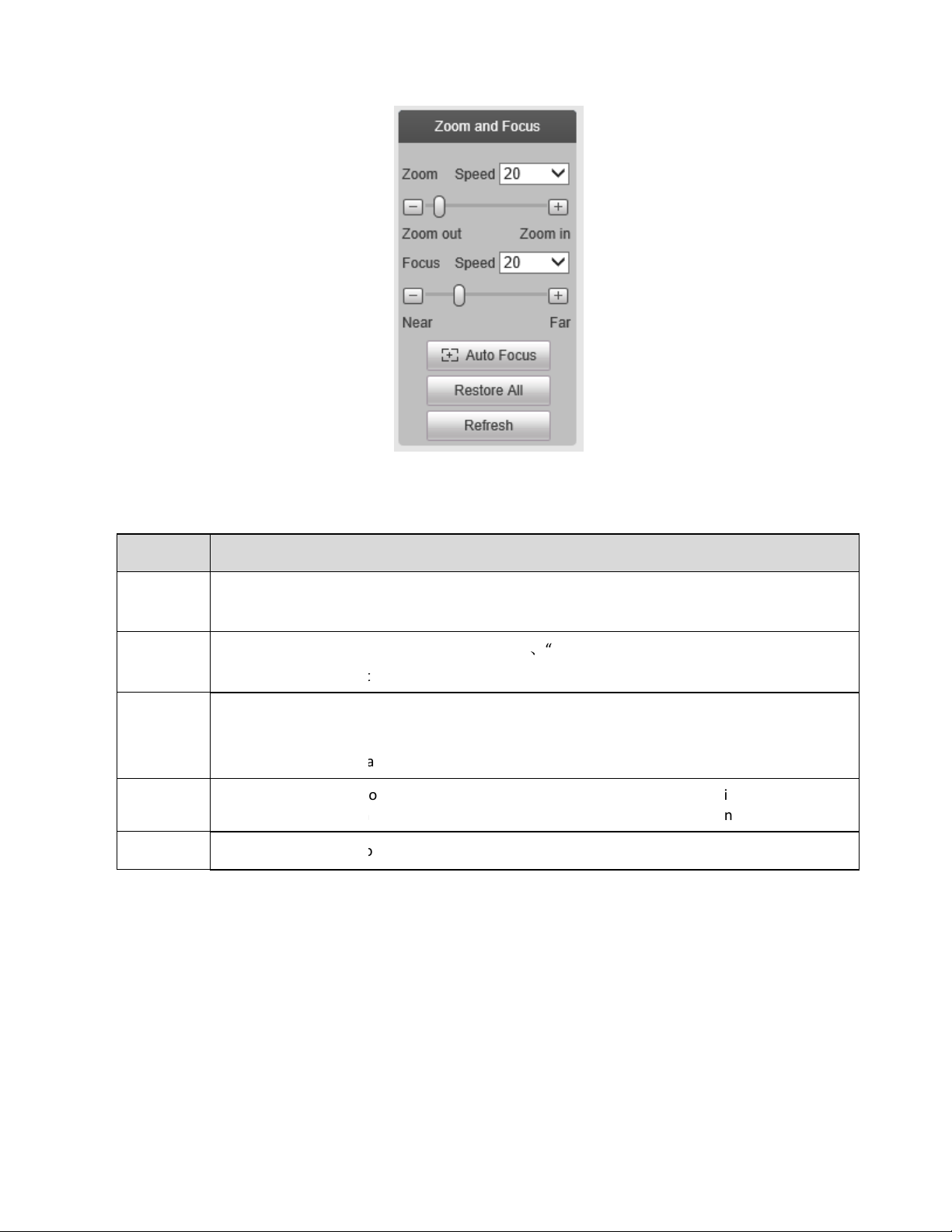
Adjust the focal length of the lens by clicking or long
t the length of one step for a
by clicking or long pressing“+”
is used to adjust the length of one step
focus
Other lens operations are not allowed during
the lens to zero position to eliminate
many zoom adjustments have been done over time and the image quality is not
Synchronize the location of
This is normally used if
Parameter Function
Zoom
Focus
Auto-focus
Reset All
Refresh
Speed is used to adjus
Adjust the focus
Speed
Click to adjust the
Note:
Resets
Figure 2-6
pressing “+”“-”buttons.
single click.
、
“-” buttons.
for a single click.
automatically.
this process.
any errors of the lens.
the slider bars after hardware zoom focusing.
clear.
7
Page 12
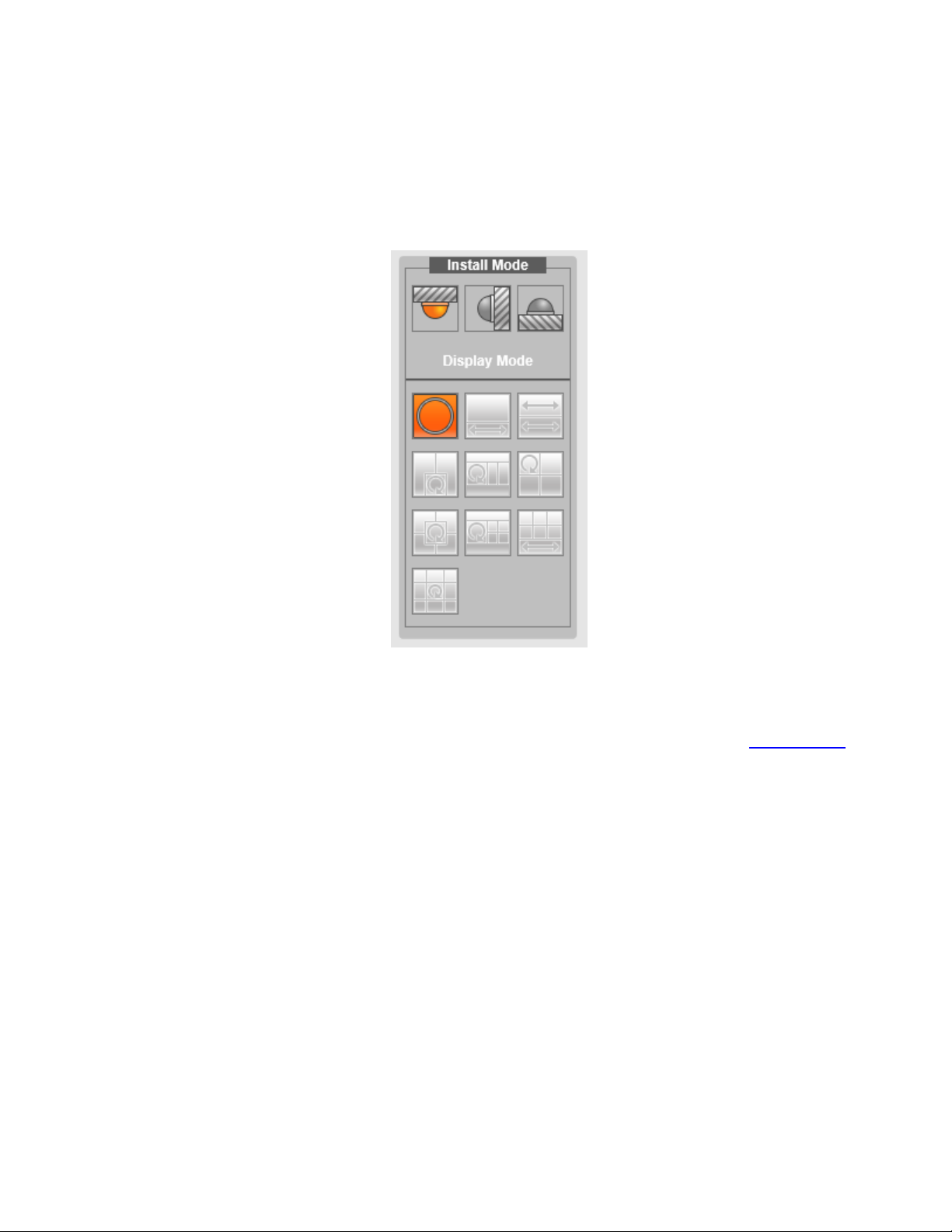
2.4 Fisheye Live View
This section applies to O6MDP2 only. In
Note: The dewarping modes shown here in live view only affects what’s being seen in the web viewer only. To
change the actual dewarped mode of the s
Live view mode can be used to help set up the desired install and viewing modes. Install modes include ceiling,
wall, and ground. Display modes include various dewarped images.
7 will be shown on the right
tream itself, it must be first configured in Setup. See
side of the window.
live view, the interface shown in Figure 2-
Figure 2-7
section 5.1.1.7.
8
Page 13
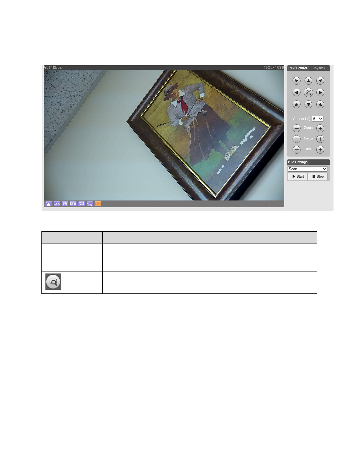
3 PTZ Control
PTZ supports eight directions: left/right/up/down/upper left/upper
right/bottom left/bottom right.
higher the value
Use mouse to draw a box
the region
zoom, focus and iris.
will rotate
See
Figure 3-1 for PTZ controls.
Parameter Note
PTZ direction
Speed
Quick Position
The
to
, higher the speed. Applies to pan, tilt,
of interest in the image. The camera
.
and zoom
9
Page 14
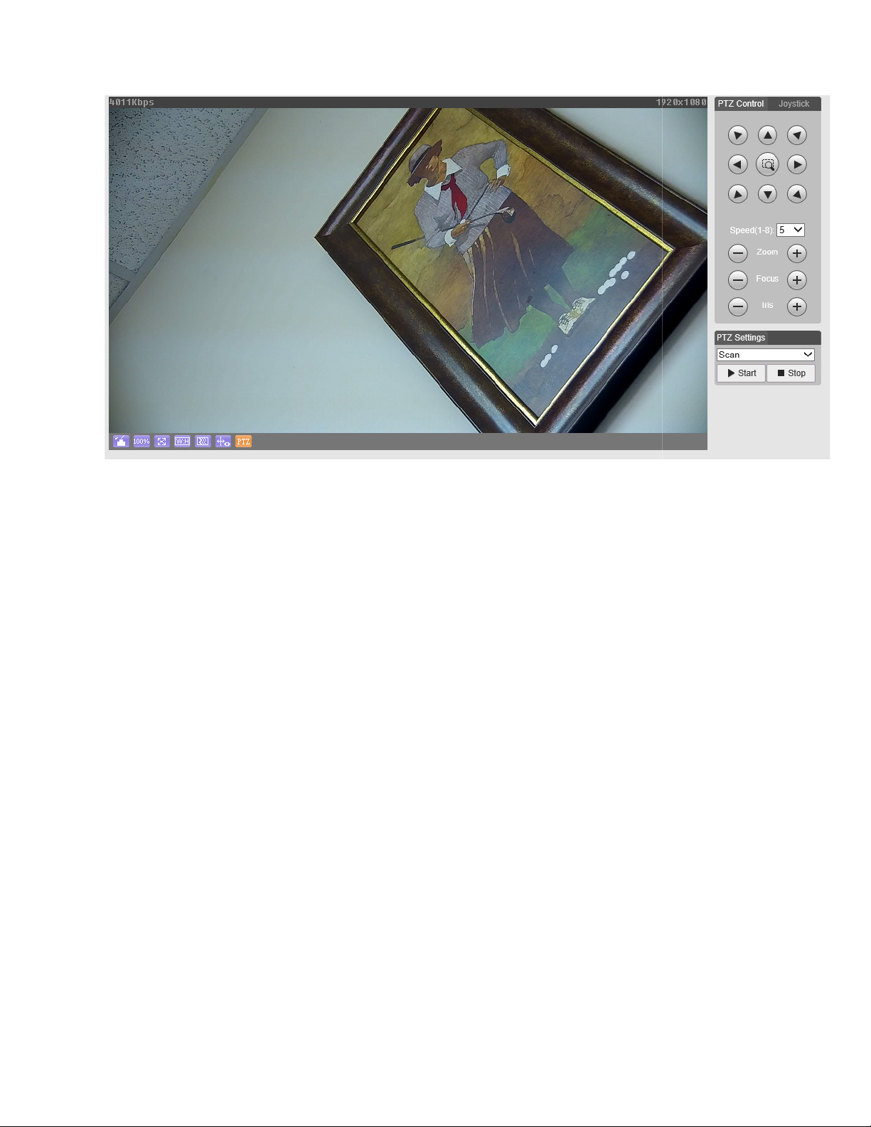
Figure 3-1
10
Page 15
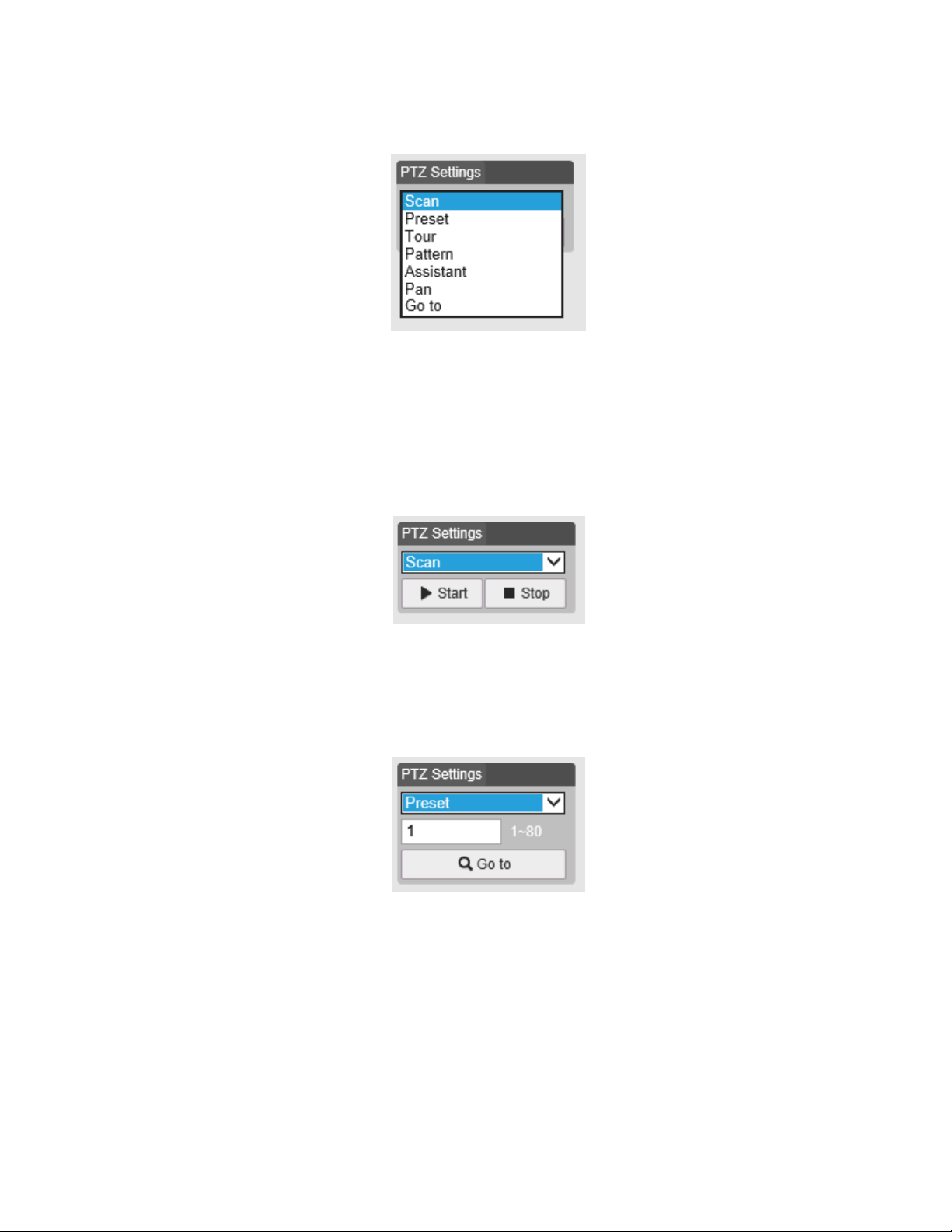
PTZ settings interface is shown in
Figure 3
Enter applicable values for tour and pattern. Click on start to begin the
function and stop to end the function.
.
3.1 Scan/Tour/Pattern/Pan
The interface is shown in Figure 3-3.
-2.
Figure 3-2
3.2 Preset
Preset interface is shown in Figure 3-4
Figure 3-3
Enter the preset value and press Go to.
Figure 3-4
11
Page 16
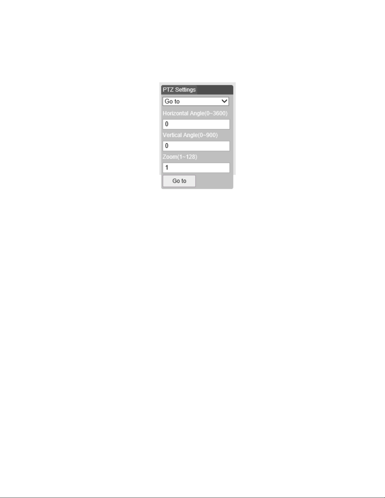
3.3 Go To
Enter the horizontal angle, vertical angle, and zoom position to go to that
Go to interface is shown in Figure 3-5.
exact position.
Figure 3-5
12
Page 17
4 Playback
Recordings on the SD card can be accessed through the web browser.
the SD card must be properly installed and configured. Refer to
playback interface is shown in
5
Note
Before playback,
instructions.
4.1 Playback
section 5.4
for detailed
The SD card
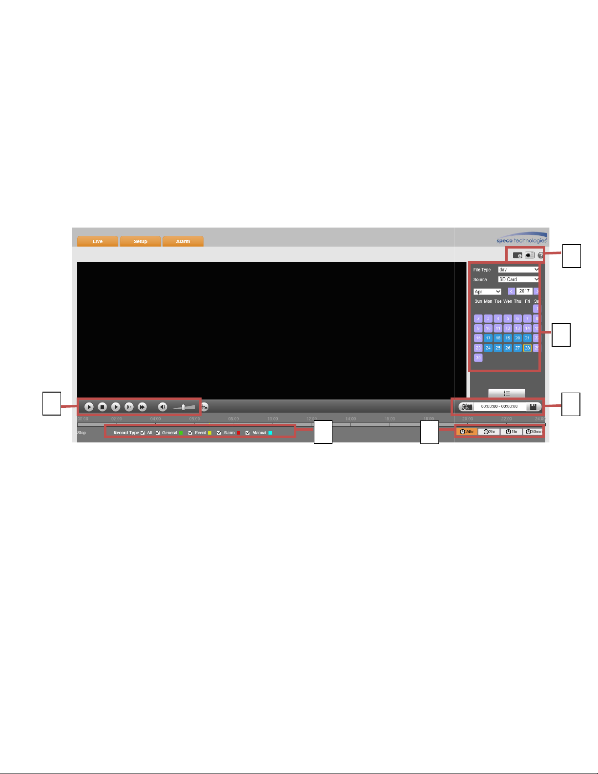
1
There are four sections:
Section 1: Play controls
Section 2: Recorded data
Section 3: Cut function
Section 4: Recording type
Section 5: Progress bar
Section 6: Additional functions
Figure 4-1.
Figure 4-1
6
2
3
4
13
Page 18
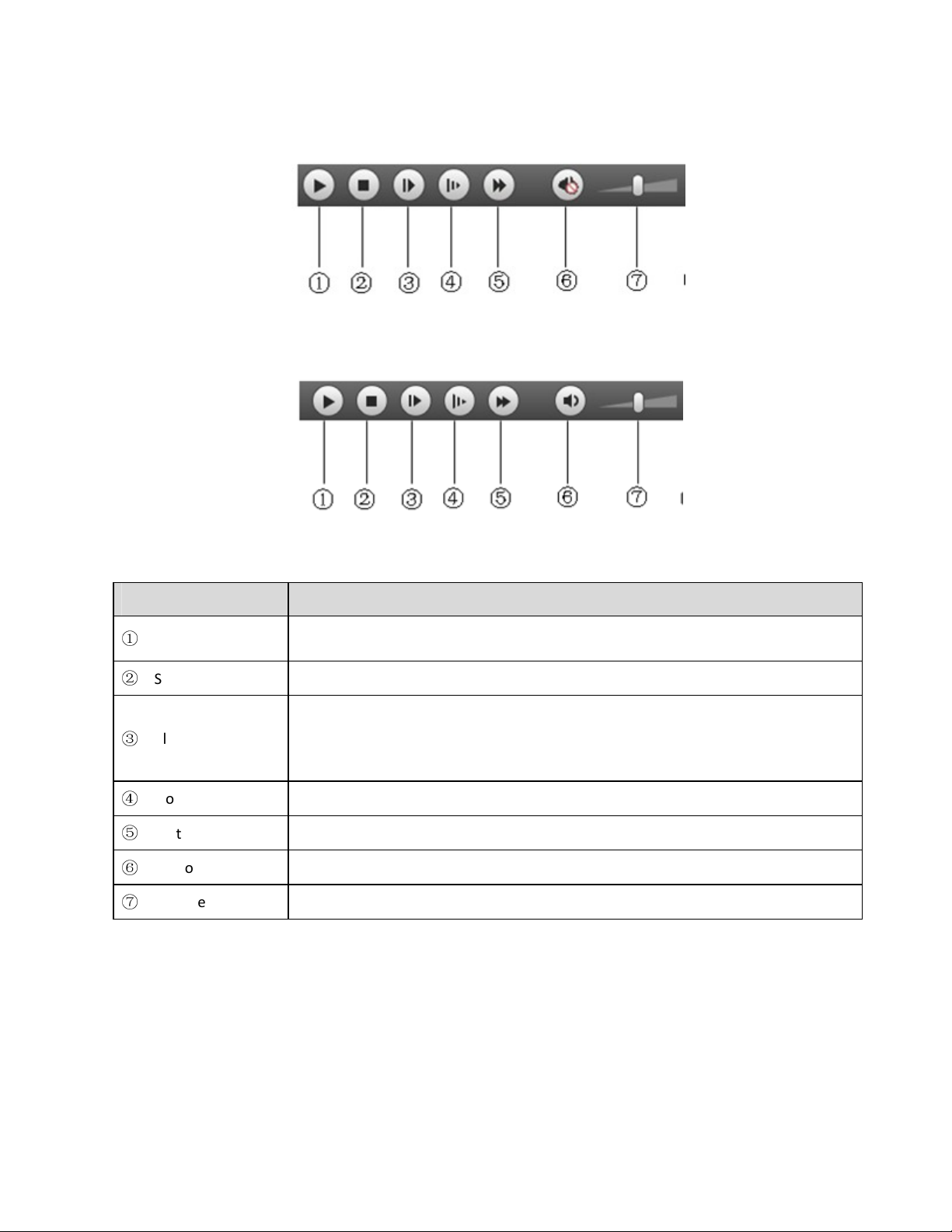
4.1.1 Play Controls
The control functions are shown in Figure 4-2 and Figure 4-3.
Figure 4-2
Figure 4-3
Parameter Function
①
Play
②
Stop
③
Play by frame
④
Slow
⑤
Fast Forward
⑥
Audio mute
⑦
Volume
Press to start playing
Press to stop playing
Press to go to the next frame.
Note:
Recording will be paused while this function is in use.
Press to slow play
Press to fast forward
Toggle audio mute
Adjust audio volume
14
Page 19
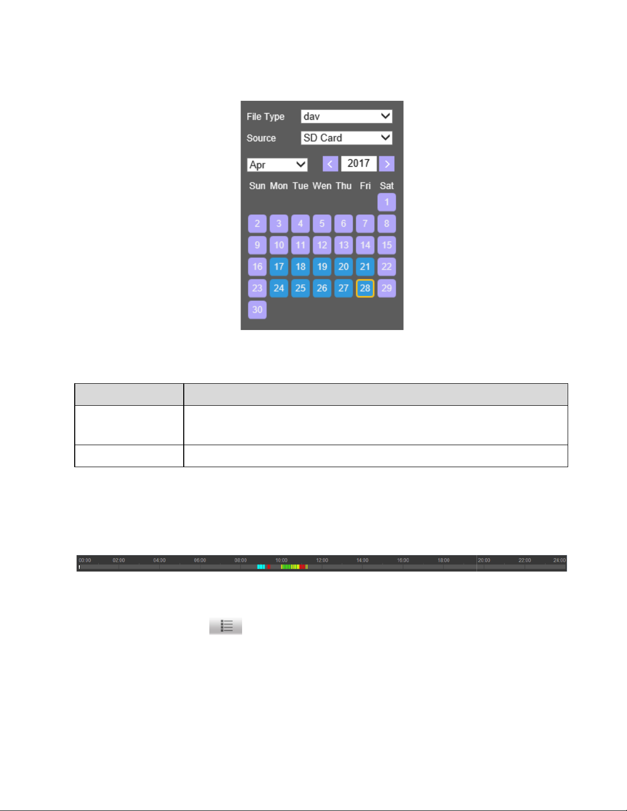
4.1.2 Playback File
Select “dav” for
Select “jpg”
Default is SD card.
in blue
yellow represents motion
start
list
reen represents
, and blue represents
file size, start time and end time
In the calendar, dates highlighted blue
have recorded data. See Figure 4-4.
Parameter Function
File Type
Data Source
Step 1. Click on a date highlighted
recording,
manual recording.
Step 2. Click on a specific time to
Step 3. Click on file list button
Figure 4-4
video playback.
for picture playback.
. The time bar will display recorded data. G
recording, red represents sensor recording
playback from that time. See Figure 4-5.
Figure 4-5
to list all available files for the selected date.
continuous
Step 4. Double click on a file in the
displayed.
to start playback for this file. The
will be
15
Page 20
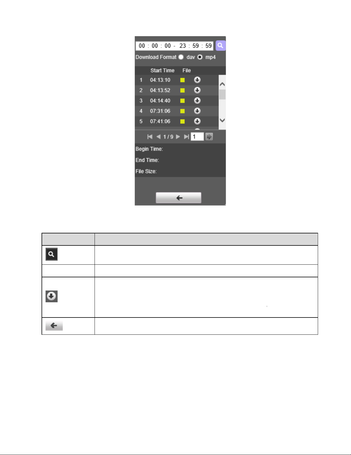
for recordings
Two formats are available for download: dav and
Click to download
>Video Setup
ystem does not support download and playback at the same time.
to go back to the
for
. Path can be specified in Setup
Parameter Function
Search
Download Format
Download
Back
Search
Setup-
The s
Click
Figure 4-6
within the specified start time and end time
to the specified path
->Path.
calendar interface.
mp4.
the date.
->Basic
16
Page 21
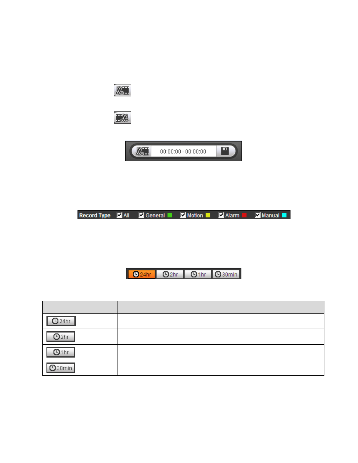
4.1.3 Playback Cut
Note:
Playback cut function will automatically pause playback as cut and playback cannot be performed at the same
time.
Step 1. Click on a time on the time bar.
Step 2. Click on the cut icon to set the selected time as the start time.
Step 3. Click on another time for the end time.
Step 4. Click on the cut icon to set the end time.
Step 5. Click on the Save button to save the file. See Figure 4-7.
Figure 4-7
4.1.4 Record Type
Only the selected recording type will be shown on the time bar. See Figure 4-8.
Figure 4-8
4.1.5 Progress Bar
Figure 4-9
Parameter Function
Changes the time bar to show a period of 24 hours
Changes the time bar to show a period of the past 2 hours
Changes the time bar to show a period of the past 1 hour
Changes the time bar to show a period of the past 30 minutes
17
Page 22
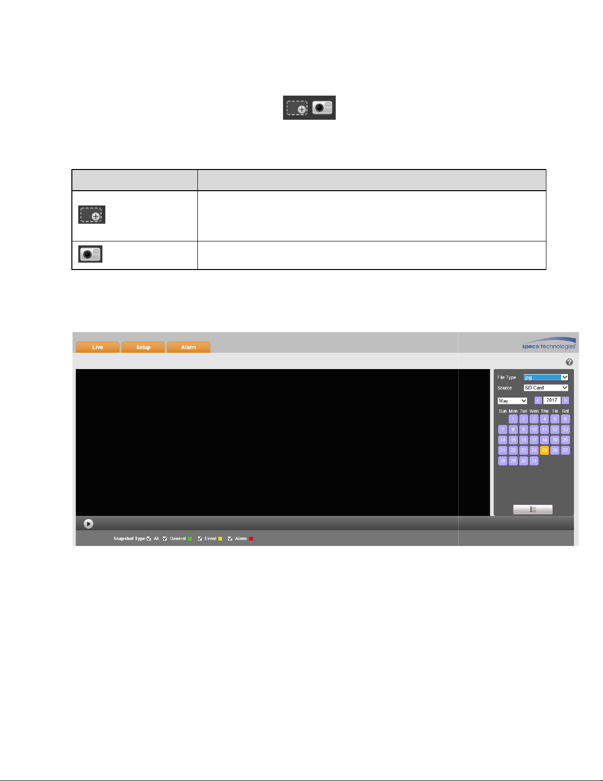
4.1.6 Assistant Function
function is shown in
Function
Enable first and then click and
mouse click
Mouse scroll button can also be used
Click to save a
for the image playback interface. Under the file type dropdown menu, select “jpg” to switch to
on any area to digitally zoom
Video playback assistant
Figure 4-10.
Figure 4-10
Parameter
Digital Zoom
Snapshot
4.1.7 Image Playback
See Figure 4-11
the interface.
drag
to restore to the original size.
.
snapshot for the video currently in playback.
in. Right
Figure 4-11
18
Page 23
5 Setup
camera settings, from the live view screen, click on the “Setup” button at the top left.
Available options may vary depending on the camera model.
> Picture”
Set picture parameters; please refer to
Adjusts the image brightness
image
overexposed
value is set too low
if the value is set
become darker and bright area
may become
To configure
5.1 Basic Setup
5.1.1 Image Setup
Note:
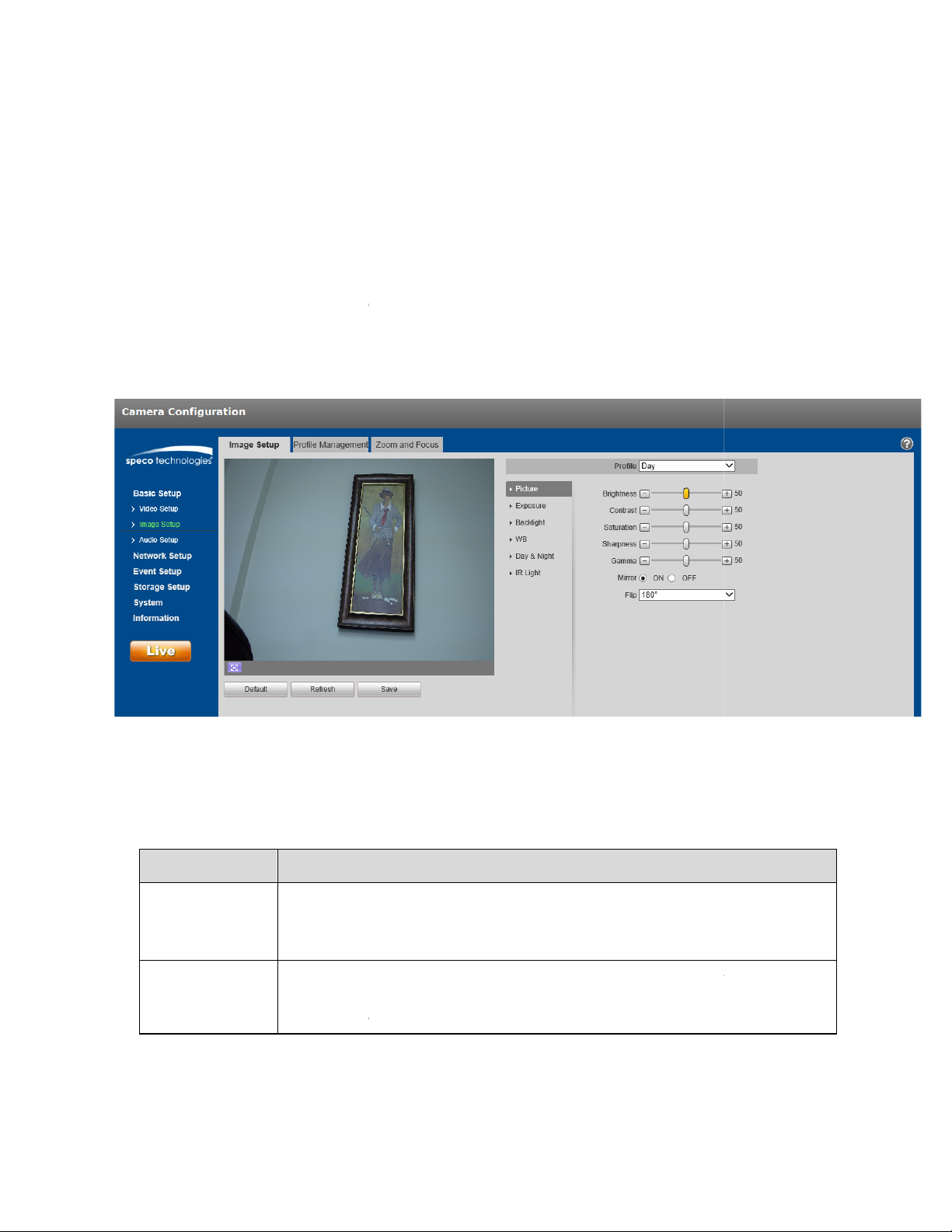
5.1.1.1 Picture
Step 1
Select “Basic Setup > Image Setup
as shown in Figure 5-1.
Step 2
Parameter
Brightness
Contrast
Note
too high.
Adjusts the
Figure 5-1
the following table for more details.
. The image may become blurry
contrast. Dark areas
if the value is set too high. The image
.
s become
blurry if the
19
Page 24
Parameter
the color
If the value is set too low, the image will look black and white. This
affect the
sharpness level of the
will also increase image noise
Changes the
Flips the image horizontally.
the display direction of the image.
Rotates the image
Rotates the image counter
Flips the image vertically
Set the main stream resolution to 1920x1080 to use the flip function.
Setup > Image Setup > Exposure” as
. The color becomes darker when the value is
sharpness level of the
Increasing
isplay range of the
Note
Adjusts
Saturation
increased.
does not
Sharpness
Gamma
Adjusts the
image.
Mirror
Changes
90°:
270°:
Flip
180:
Note:
Step 3
Click “Save” to save the settings.
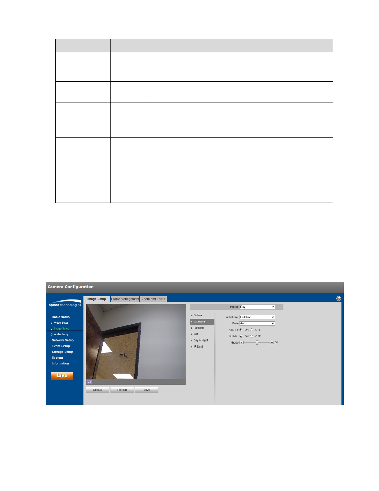
5.1.1.2 Exposure
Step 1
Select “Basic
saturation
overall brightness of the image.
edge on the image.
.
image brightness and improve the dynamic d
clockwise 90°
-clockwise 90°
.
shown in Figure 5-2.
the sharpness
Figure 5-2
20
Page 25

Step 2
Set exposure parameters; please refer to the following table for more details.
Parameter Note
Outdoor
Anti-flicker
Mode
50Hz
60Hz (used in the United States)
Camera exposure mode
Note:
When “Anti-flicker” is set to “Outdoor”, the “exposure mode” can
be set as “gain priority” or “shutter priority” mode.
The options are:
Auto: image brightness is adjusted automatically according to the
environment.
Gain priority: The device can adjust automatically according to the
gain range set during normal exposure range in different scenes.
Shutter priority: The device can adjust automatically according to
the shutter range set during normal exposure range in different
scenes.
Manual: Set the gain value and shutter value manually.
Auto Iris
3D NR
Grade
Step 3
Click “Save” to save the settings.
The lens iris can auto adjust the size according to the environment
after auto iris is enabled, then the image brightness will change
accordingly.
The iris value reaches the max when disabling auto iris, the lens
iris will not change according to the environment brightness.
Multiple frames are processed and then noise is reduced by using the
interframe information between the previous and the latter frame.
This can be applied when 3D NR is enabled.
Increase the value for a bigger effect.
21
Page 26
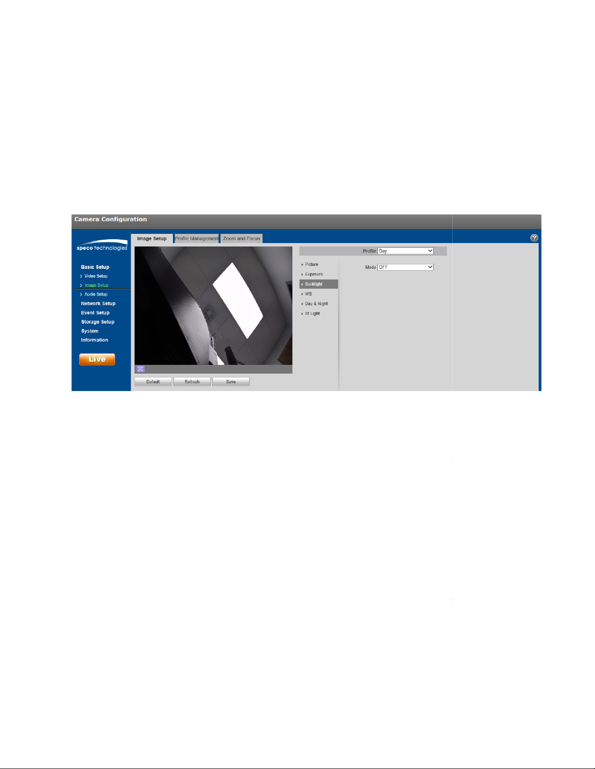
5.1.1.3 Backlight
are BLC, WDR and HLC
compensates for high backlight
image
camera is pointing towards the door.
reduces exposure from bright light sources
, entrance and exit of the parking lot
> Backlight”,
default mode or customized mode.
is selected
image to be seen.
will lower the brightness of the area with high brightness and enhance the
of the area with low brightness
pointing towards the entrance, where there is a lot of light coming in.
There may be video loss of a few seconds when the camera is switched from non WDR mode to WDR mode.
“HLC”, the system will
areas behind a subject to make the subject more visible.
with a large dynamic range. Typically used for lobbies, where the
can be applied in areas such as
will display the interface shown in Figure 5
to the environment, to make the
custom area in the image can be selected
s such as the camera in a lobby
and decrease the size of the halo area
Backlight mode options
• BLC:
• WDR: balances washed out
• HLC:
toll gates
Step 1
Select “Basic Setup > Image Setup
.
such as headlights. This
s, etc.
which
-3.
Step 2
Set the backlight parameter.
BLC can be set to
When “Default” mode
darkest part of the
When “Customized” mode
that area.
When set to “WDR”, the system
brightness
Note:
When set to
Step 3
Click “Save” to save the settings.
Figure 5-3
, the system adjusts automatically
is selected, a
. This is very helpful in situation
reduce the high brightness areas
, to compensate for
.
22
Page 27
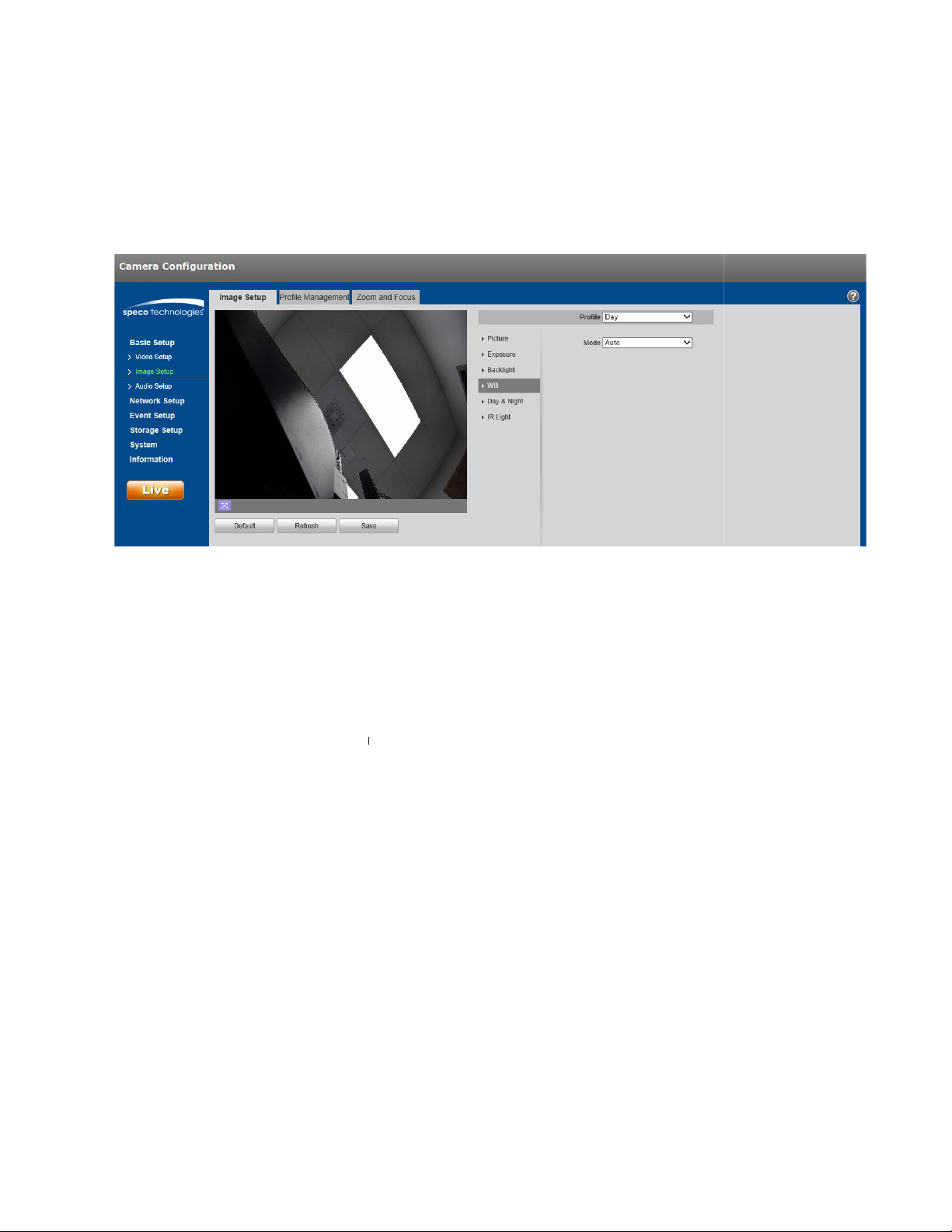
5.1.1.4 WB
adjust colors in the image so that objects that appear white in person are shown as
> WB”,
will
“Natural”, the system
“Street Lamp”, the system
“Outdoor”, the system
“Manual”, red gain and blue gain
a custom area can be defined in the image
ifferent color temperature
4.
automatically for the white balance depending on the
based on an outdoor scene at night.
most outdoor scenes with natural light and
the system can
WB (white balance) is used to
white in the camera.
Step 1
Select “Basic Setup > Image Setup
which will display the interface shown in Figure 5-
Step 2
Set the mode.
When set to “Auto”, the system
environment.
When set to
When set to
When set to
artificial light.
When set to
When set to “Regional Custom”,
compensate for the d
Step 3
Click “Save” to save the settings.
Figure 5-4
compensate
will compensate based on natural light settings.
will compensate
will compensate based on
values can be set manually.
, which
s of the images in the area.
then
23
Page 28
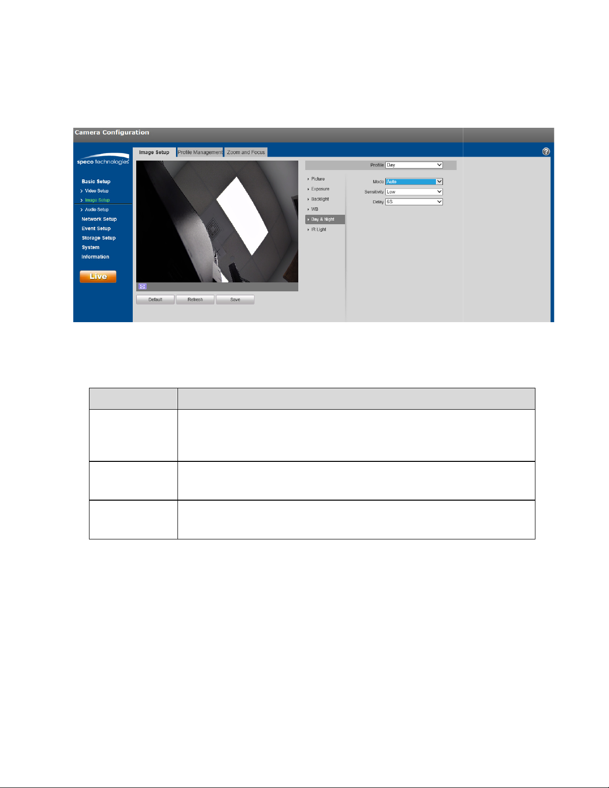
5.1.1.5 Day & Night
color and monochrome switching
> Day & Night”
refer to
Color: The camera image is
Auto: The camera
depending
Black & white:
The parameter can be set when the “Day/Night Mode” is
Higher sensitivity means that the mode will switch back and forth from color and
black and white more easily.
The parameter can be set when the “Day/Night Mode” is
This is to set a delay for switching between modes
situations such as light flickering.
always
displayed
in color
.
color and black & white,
in black & white
set to
“Auto
set to
“Auto”.
This may be helpful in
”.
This is to set up
Step 1
Select “Basic Setup > Image Setup
Step 2
To set the day & night parameters,
.
, shown in Figure 5-5.
Figure 5-5
the following table for more details.
Parameter Note
Mode
Sensitivity
Delay
Step 3
Click “Save” to save the settings.
switch automatically between
on the light level.
The camera image is always displayed
.
.
24
Page 29
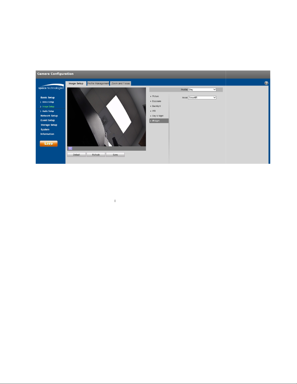
5.1.1.6 IR Light
IR LEDs can be controlled in this section
> IR Light”
brightness
“Smart IR”, the system
IR LEDs will not operate even in darkness
® VMS and the N32NX NVR is able to dewarp the fisheye view from the O6MDP2 IP camera model.
For other recording options, the camera itself can be configured to send out a dewarped image in the stream
Select “Basic Setup > Image Setup > Fis
according to the actual scene.
Step 1
Select “Basic Setup > Image Setup
Step 2
Set the mode.
When set to “Manual”, the
When set to
When set to “Off”,
Step 3
Click “Save” to save the settings.
5.1.1.7 Fisheye Setup
SecureGuard
.
, shown in Figure 5-6.
Figure 5-6
of the IR LEDs can be set manually.
will adjust the LED brightness
.
itself.
Step 1
heye”. See Figure 5-7.
25
Page 30

Select the desired parameters. Description are listed in the table below
Three installation modes are available:
depending on the
When a specific record mode is set, the output stream will
This is
helpful for situations where a recorder does not have the
After setting the mode, click Save to change to that view.
according to the different
Note: Any option other than
“1O” will cause the fisheye viewing option to be hidden
Displays two
1O+3R: original image + 3 independent sub images
images support digital zoom and pan, which can be
Step 2
Parameter
Installation Mode
Record Mode
Function
Ceiling, wall, and ground.
The orientation of the image will vary
mode.
be the dewarped image on the mode that was set.
ability to dewarp the image.
Available record modes will vary
installation modes.
1O: Original fisheye image.
in live view.
1P: 360°rectangular panoramic image.
2P: Available for “Ceiling” or “Ground”.
180°rectangular images.
. All
done in live view.
1R: 1 independent sub image.
2R: 2 independent sub images.
4R: 4 independent sub images.
26
Page 31

Image settings can be set to different values depending on the profile that’s being used.
Profile Management”
“Normal”, the system will monitor according to the normal config
the profile can be set to always use the D
display the “Profile Management”
ay configuration or the Night
5.1.1.8 Profile Management
Step 1
Select “Basic Setup > Image Setup >
Step 2
Set the profile.
When set to
to
tab.
uration.
When set to “Full Time”,
configuration.
Figure 5-8
Figure 5-9
27
Page 32

When set to “Schedule”,
a specified period of the day can be used for the Day configuration and the rest of
the day for the Night configuration. Click and slide the bar to set the time period.
Click “Default” to restore the device to
motorized lens
> Zoom and Focus”
lick “Refresh” to check the latest config
Step 3
Click “Save” save the settings.
Note:
the device.
5.1.1.9 Zoom and Focus
Note:
This applies to only models with
Step 1
Select “Basic Setup > Image Setup
Figure 5-10
the default settings. C
.
, shown in Figure 5-11.
uration of
28
Page 33
by pressing
to adjust the focus automatically after a manual adjustment.
image fails to focus after a few times of adjustment
of the lens.
Adjust the speed as desired.
the lens
Step 2
The focal length can be set by pressing
Step 3
Focus can be adjusted manually,
Note:
Click “Auto Focus”
If the
the accumulative errors
Figure 5-11
“+”, “-“ for Zoom or dragging the slider bar.
“+”, “-“ or dragging the slider block.
, click “Restore All’ to reset
and remove
29
Page 34
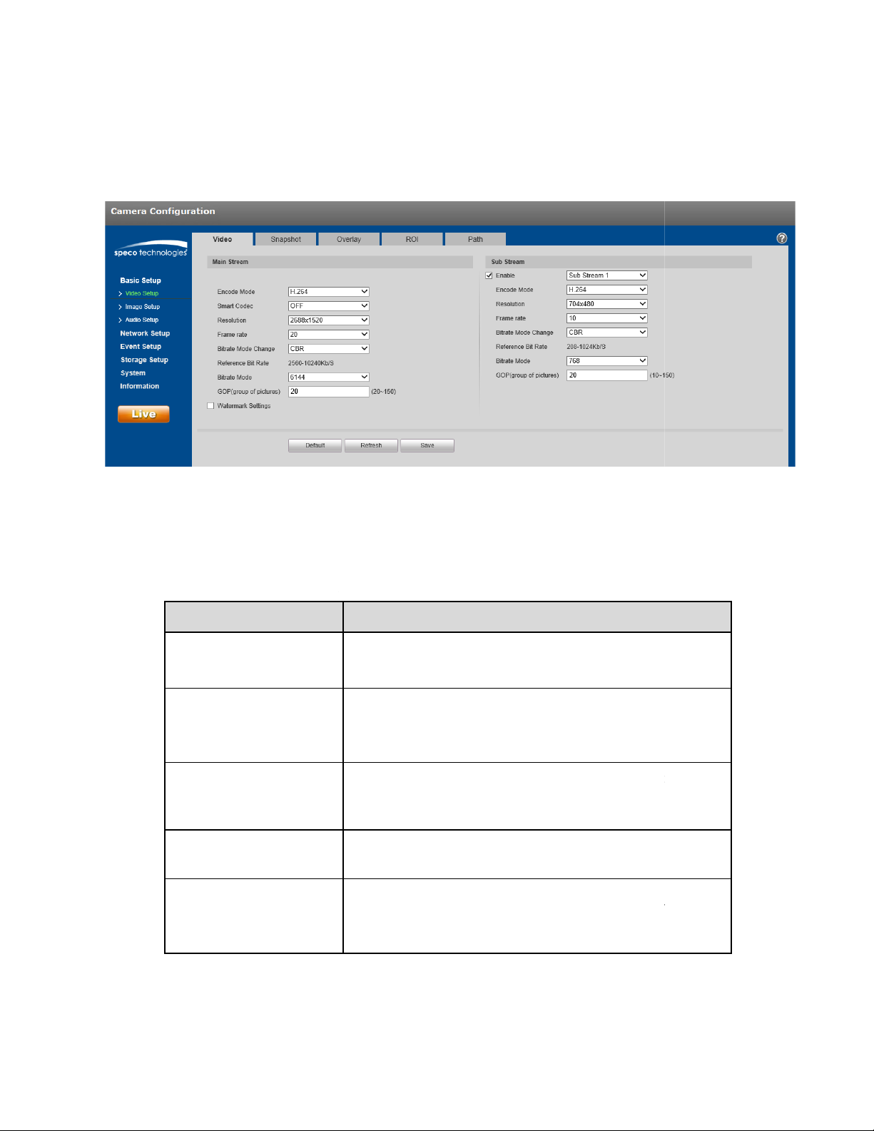
5.1.2 Video Setup
> Video”
for more details
Select “Enable” to enable
the
sub stream
.
Depending on the model, there may be a second sub stream
Select the compression to be used.
(depending on the
Multiple resolution options are available for each stream.
Resolution is the equivalent to the size of the image. Higher
Select the applicable frame rate for each stream, measure in
CBR (constant) means that bitrate will be kept at a constant
value even with various changes in the scene. VBR (variable)
sted according to the scene
5.1.2.1 Video
Step 1
Select “Basic Setup > Video Setup
Step 2
Refer to the following table
shown in Figure 5-12.
Figure 5-12
on setting the video stream parameters.
Parameter
Sub Stream Enable
Encode mode
Resolution
Frame Rate
Bit Rate Mode
Function
available.
Options are H.264, MJPEG, and H.265
model)
minimum bit rate is required for higher resolutions.
fps (frames per second).
means that bitrate will be adju
changes.
30
Page 35

Parameter
Figure 5
Please refer to the following sheet for detailed information.
Function
There are two modes:
.
Same resolution as the main stream resolution.
Recommended bit rate range based on the resolution.
Set the bit rate value. Note that higher bit rate provides a
better image quality, but also results in more storage usage.
SVC can dynamically adjust the stream based on the network
conditions. Can be turned on or off depending on the client
Determines how many P frames are allowed in between two
is the beginning frame of a unique scene. A
GOP value of frame rate x 2 or lower is recommended.
Enter the watermark text to be used for verification.
G
eneral (
schedule
-
based
) and
Event (
alarm
.
-
Function
Reference Bit Rate
Bit Rate
SVC (scalable video
coding)
GOP (group of pictures)
Watermark Settings
Watermark Character
Step 3
Click “Save” to save the settings.
5.1.2.2 Snapshot
The snapshot interface is shown as in
being used.
I frames. I frame
Check to enable watermarking on the video.
-13.
Parameter
Snapshot type
Image size
based)
Figure 5-13
31
Page 36

Quality
Sets the image quality, with 6 being the highest quality.
Interval of how many seconds between snapshots.
Please refer to the following sheet for detailed information.
Function
Up to 4 privacy mask zones can be defined.
Privacy mask blocks out the image in the defined areas.
Time information can be shown in the video
The position can be changed by dragging it with the mouse
This shows the nickname of the device/channel on the screen.
Position can be changed with the mouse.
User
Position can be ch
An image can be set as an overlay onto the stream.
Requirements for picture uploading are listed in the section.
overlay
if enabled.
-
defined text can be displayed.
cannot be used at the same time.
Interval
5.1.2.3 Video Overlay
Figure 5-14 shows the OSD options.
Parameter
Privacy Masking
Time Title
Channel Title
Text Overlay
Picture Overlay
5.1.2.4 ROI (Region of Interest)
Note:
Text
Figure 5-14
anged with the mouse.
and picture overlay
32
Page 37

Check “Enable” and use the mouse to define the desired region. Click “Save” to save the settings. See Figure 5
15.
ce not found.
cut download (within playback, a clip with a specific time period can be defined to be
setup.
16 shows the interface for setting up storage paths for snapshots and
5.1.2.5 Path
Error! Reference sour
recordings.
There are 4 types of save paths:
• Live view snapshot
• Playback snapshot
• Playback clip download
• Playback video
downloaded)
Click the Save button to save the
-
Figure 5-15
33
Page 38
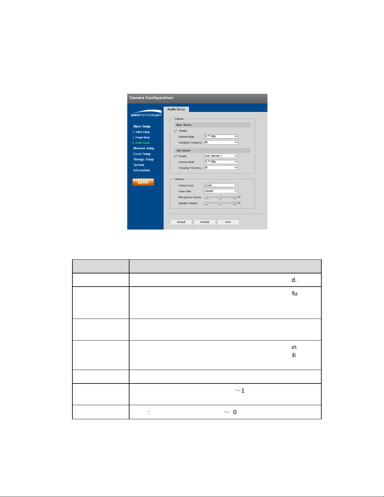
5.1.3 Audio
Applies only to models with audio capability.
Figure 5
Please refer to the following sheet for detailed information.
Function
Audio can be enabled only when
Select the applicable compression between G.711A, G.711Mu,
G.726, and AAC
This applies to both the audio input and 2
Options are 8k, 16k, 32k, and 48k.
Device needs
In mode. It does not
source under Mic mode.
Enable
Adjust
Speaker
V
olume
Adjust
the video stream is enabled.
external audio input source under
external audio input
The audio interface is shown in
Figure 5-16
-17.
Parameter
Enable
Encode mode
Sampling
Frequency
AudioIn Type
Noise Filter
Microphone
Volume
Figure 5-17
.
to connect to an
Line
to filter relevant noise.
the microphone volume from 0~100.
need to connect to an
.
-way audio.
the speaker volume from 0~100.
34
Page 39

are both supported
the web viewer
Please refer to the following sheet for detailed information.
Function
Set the device name. Maximum of 15 characters is supported.
Default is wired.
Select between static and DHCP. If setting to static, make sure that
the network does have static IP addresses available for use. When
using DHCP, make sure that the network has the capability to assign
an IP address to the device. Typically, a reside
router will have a built
Displays the Mac address of the device.
Select IPv4 or IPv6.
Can be modified if in static mode.
Define the subnet mask. For a typical case,
255.255.255.0.
Define the gateway of the network. Example: if the IP address is
192.168.1.150, the gateway will be 192.168.1.1.
. IPv4 supports static IP and DHCP. IPv6 supports static IP
will automatically jump to the new IP address.
ntial or commercial
5.2 Network Setup
5.2.1 IP Address Setup
For IP address setup, IPv4 and IPv6
only. If the IP address is modified,
Figure 5-18
Parameter
Host Name
Network Type
Mode
Mac Address
IP Version
IP Address
Subnet Mask
Default Gateway
-in DHCP server.
the mask is
35
Page 40

Preferred DNS
DNS IP address.
Alternate DNS IP address.
This can be used
the Mac address
Before the operation
in the same LAN.
to the
Step 1
Step 2
Step 3
commands.
Step 4
Step 5
such as “Reply from 192.168.0.125 …” from the command output
.
Step 6
the camera
Figure 5
by utilizing
and the PC
to the
the same LAN.
of the network camera
the following
output information
the IP address to access
Alternate DNS
Enable ARP/Ping
set device IP
address service.
to modify or set the device IP address
.
, make sure the network camera
Refer
lines
steps listed below.
: Set the network camera and the PC to be on
: Get the Mac address from the label
: Go to the cmd prompt and then enter
arp –s <IP Address> <MAC>
ping –l 480 –t <IP Address>
Such as:arp -s 192.168.0.125 11-40-8c-18-10-11
ping -l 480 -t 192.168.0.125
: Reboot the device.
: Check if the setup is OK by looking at the
: Open the browser and then enter
.
are
.
5.2.2 Connection
5.2.2.1 Connection
The connection interface is shown in
-19.
36
Page 41

Figure 5-19
Refer to the following table for more information. Typically, if the device is being installed on an NVR or
SecureGuard in the same LAN, these ports can stay at the same values.
Parameter Function
Max
connection
TCP port Port range is 1025~65534. The default value is 37777.
UDP port Port range is 1025~65534. The default value is 37778.
HTTP port Port range is 1025~65524. The default value is 80.
RTSP port The default value is 554.
HTTPs Port HTTPs communication port, range is 1025~65534, default is 443.
Note:
0~1024, 37780~37880, 1900, 3800, 5000, 5050, 9999, 37776, 39999, 42323 are all special ports. User
cannot modify them.
Avoid using default values of other ports.
Defines the number of max web connections that are allowed for the device. The
value ranges from 1 to 20. Default connection amount is 10.
5.2.3 PPPoE
The PPPoE interface is shown in Figure 5-20.
Enter the username and password that were provided by the ISP, and click “Enable”. The network camera will
automatically establish a network connection if the credentials are correct. The IP address will be automatically
modified to the dynamic IP address of the acquired WAN.
Note:
Disable UPnP before enabling PPPoE, which can cause a conflict.
37
Page 42
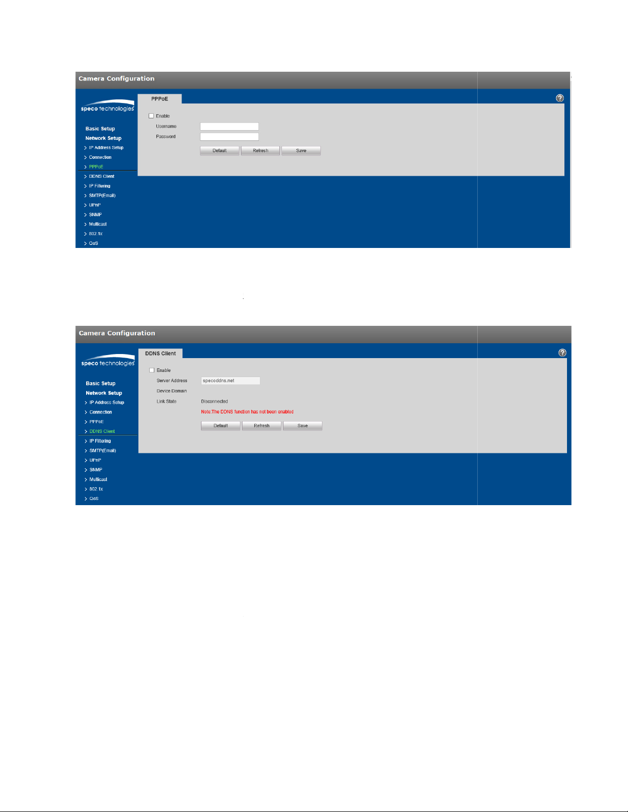
5.2.4 DDNS Client
Figure 5
Enable DDNS and click “Save”. If the connection is
Figure 5
ified IP or Mac addresses
Individual IP addresses or IP segments can be used.
After adding the IP/Mac addresses, click on Truste
successful, the status will indicate that it is connected.
d Sites to enable filtering. Click “Save” to save the settings.
The DDNS interface is shown in
Figure 5-20
-21.
Figure 5-21
5.2.5 IP Filtering
The IP filtering interface is shown in
This can be set up so that only spec
-22.
can access the device.
38
Page 43
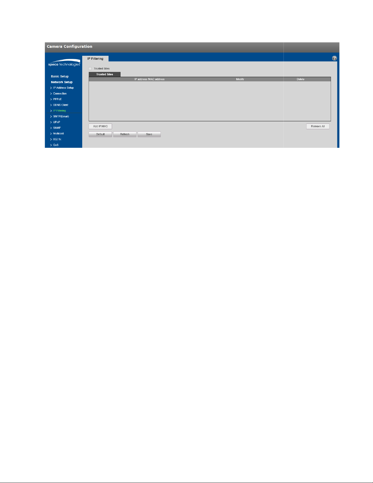
Figure 5-22
39
Page 44

5.2.6 SMTP (Email)
Figure 5
information.
Function
Email server, such as smtp.gmail.com, etc
Default value is 25.
email
information of the sender
The
user name of the
The
password of
Sender
S
elect SSL
Enter email subject
A snapshot of the event can be sent out as an attachment if
enabled.
Enter
can be entered
.
email function
sender
’s email account.
sender
’s email account.
’s email address.
, TLS or none
.
.
receiver
’s email address here. Max
imum of
three addresses
The email interface is shown in
-23.
Figure 5-23
Refer to the following table for more
Parameter
SMTP Server
Port
Anonymity For
User Name
Password
Sender
Authentication
(Encryption mode)
Title (Subject)
Attachment
Mail receiver
Modify as necessary.
servers which support anonymous
wouldn’t be displayed.
.
. The
40
Page 45

Parameter
Function
The send interval range is
no interval.
The system will
Before the email test,
information.
UPnP can be used to allow port forwarding on a router without user intervention. Typically, residential routers
have UPnP enabled while commercial routers have it disabled by default. See Figure 5
from 0 to 3600 seconds. 0 means there is
send out an
email once to test the
connectivity
24 for the
.
Interval
Email test
5.2.7 UPnP
make sure to save the email setup
-
interface.
Figure 5-24
41
Page 46

5.2.8 SNMP
Figure 5
install
to activate the new setup.
information.
Function
Check the version to be used.
cannot be checked until v3 is
The value ranges from 1 to 65535. The default
an SNMP management tool and set the parameters.
The parameters in the first table apply to all versions
If v3 is checked, the other version
port is UDP port
The SNMP interface is shown in
Before using SNMP, make sure to
device must be restared
-25.
After setup, the
Refer to the following table for more
and v3.
Parameter
SNMP Version
SNMP port
Figure 5-25
- v1, v2,
unchecked.
161.
42
Page 47

Parameter Function
Read
-
only access to all SNMP targets, default is public.
Read/write access
to all SNMP targets, default is private.
The destination address of the Trap information from the proxy
Address
for
where to send Trap message.
Port which send
s Trap message, default is 162, range 1~65535.
Default is
public
.
Default is
private
.
Read community
Write community
Trap address
Trap Address
Trap Port
Note: Only number, letter, _, and – are supported.
Note: Only number, letter, _, and – are supported.
program of the device.
The parameters below are available when SNMP v3 is enabled.
Parameter Function
SNMP Version SNMP v3
Read-only
Username
Read/Write
Username
Note:
Name can consist of numbers, letters and underline.
Note:
Name only can be number, letter and underline.
Authentication
Authentication
Password
Encryption
Encryption
Password
Select MD5 or SHA, default is MD5.
Password must be not less than 8 characters.
CBC-DES
Password must be not less than 8 characters.
43
Page 48

5.2.9 Multicast
Figure 5
Multicast is a transmission mode of data packet
multicast can be used
make sure that network switches/routers that are being used have multicast support.
information.
Select to enable multicast function. Main stream and sub stream cannot be used at
the same time.
Main/sub stream multicast
239.255.255.255
Multicast port. Main stream is
and the range is
When there are multiple destinations that will receive the
.
and its range is
sub stream2 is 40032
The multicast interface is shown in
same video stream,
-26.
s.
to reduce bandwidth and CPU load on the device
Figure 5-26
To set up multicast,
Refer to the following table for more
Parameter Function
Enable
Multicast address
Port
.
1025~65534.
default address is 224.1.2.4
40000, sub stream1 is 40016,
224.0.0.0
~
44
Page 49

5.2.10 802.1x
port based network access control protocol
information.
Function
PEAP (protected EAP protocol).
Enter the user name
Enter the password.
interface is shown below.
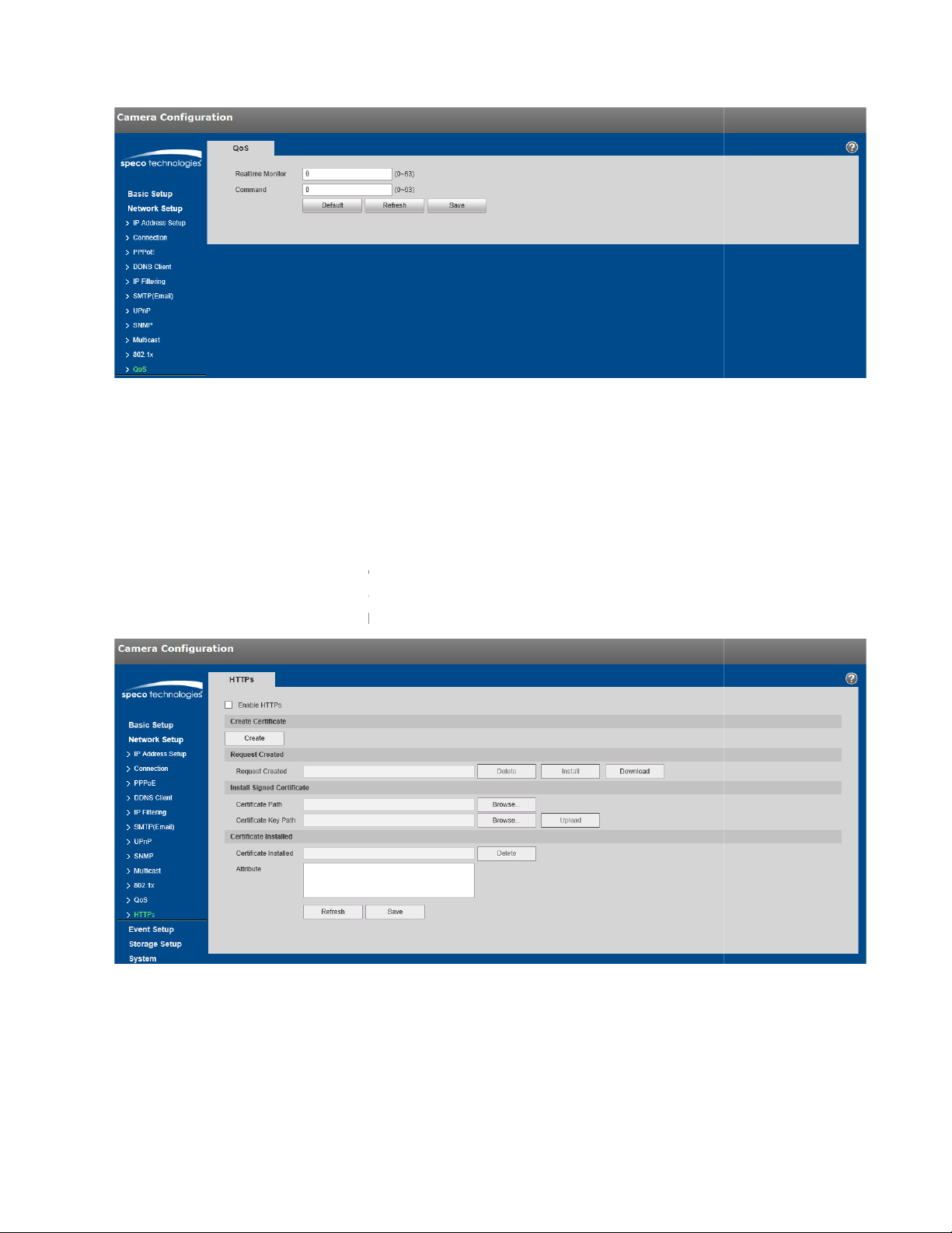
QoS can be set for stream viewing and control for the IP camera. Specific DSCP values (in decimal format) can be
set for each, with the values ranging from 0 to 63.
for a
802.1x (
to a LAN.
Refer to the following table for more
) provides an authentication method
Figure 5-27
device to connect
Parameter
Authentication
Username
Password
5.2.11 QoS
The QoS (quality of service)
, which is authenticated by the server.
See Figure 5-28.
45
Page 50
devices that have HTTPs capability, a certificate can be created or a signed certificate can be uploaded.
signed certificate.
To create a certificate, follow the directions below
shown in Figure 5
a dialog box will pop up, which is shown in Figure 5
5.2.12 HTTPs
For
Step 1
Create a certificate or upload a
1. Select “Network Setup > HTTPs”,
Figure 5-28
.
-29.
Figure 5-29
2. Click “Create” and
-30.
46
Page 51

3. Fill in all fields and click “Create”.
A message will pop up stating that the certificate has been created
re that the IP address or the domain name is the same as that of the device.
will be installed
Click “Download” and save the file on the PC
successfully. Make su
4. Click “Install” and the certificate
5.
Figure 5-30
on the device.
.
47
Page 52

Figure 5-31
6. Double click on the downloaded file. The system will display the shown in Figure 5-32.
48
Page 53

Figure 5-32
7. Click “Install Certificate” and the Certficate Import Wizard will show, shown in Figure 5-33.
49
Page 54
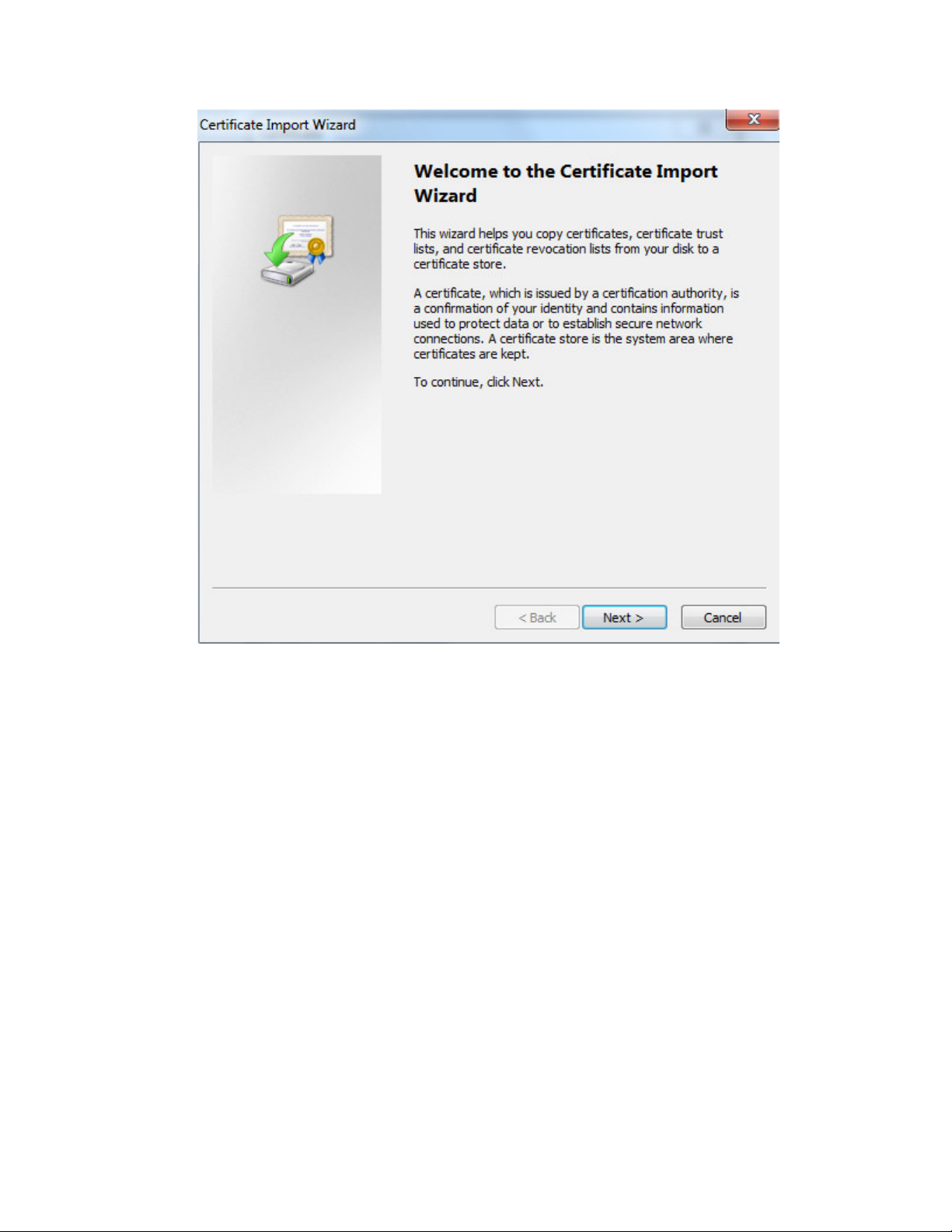
Figure 5-33
8. Click “Next” and select “Place all certificates in the following store”. Click on Browse and select “Trusted Root
Certification Authorities”.
50
Page 55

Figure 5-34
9. Click “Next” and “Completing the Certificate Import Wizard” will show, which is shown in Figure 5-35.
51
Page 56

Figure 5-35
10. Click “Finish”, and “Security Warning” dialog box will show, which is shown in Figure 5-36.
52
Page 57

Figure 5-36
11. Click “Yes” and a dialog box will pop up showing that the import was successful. Click “Ok” to complete
downloading the certificate.
Figure 5-37
To use the “Install Signed Certificate” option, follow the directions below.
1. In the HTTPs interface, select the certificate path and the certificate key path and click Upload.
2. Install the root certificate - refer to steps 6~11 for details.
3. Check “Enable HTTPs” and click “Save”. The device will reboot.
4. Use HTTPs to log in by entering the IP address in the browser, starting with https://. The browser will show a
certificate error if the certificate is not installed, which is shown in Figure 5-38.
53
Page 58
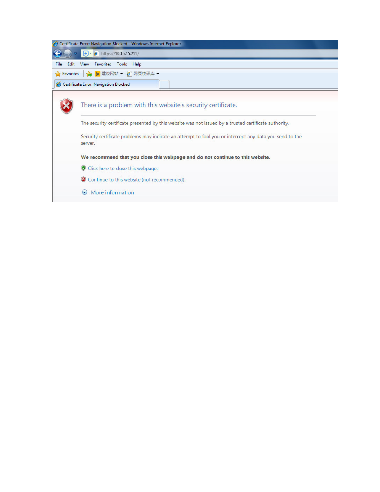
Figure 5-38
54
Page 59

5.3 Event Setup
detect
to show the interface in
motion detection interface
5.3.1 Video detection
5.3.1.1 Motion Detection
Step 1
Select “Event Setup > Video Detection
Figure 5-39.
> Motion Detection” to display the
shown in
Step 2
Select “Enable” to enable motion
Step 3
Set up motion detection zone.
1. Click “Setup” for Area
Figure 5-39
ion.
Figure 5-40.
55
Page 60

2.
Up to 4 different zones can be set, with a different set of defined areas, sensitivities, and threshold values.
The name field is the nickname for the corresponding zone.
value means that it is easier to trigger a motion event. The threshold value represents how
much of the overall motion detection zone needs to have motion in order for the motion event to trigger.
defined as the motion zone
Refer to the table below for more details on the parameters
Set up the schedule for when motion alarms will get generated by the device.
: In cases where the IP camera is recording to an NVR, if there is a period of
time where motion alarm is disabled in the camera, then even if motion
recording is enabled on the NVR, the camera will not send any motion alarms to
the NVR during that time pe
3. Higher sensitivity
Figure 5-40
The entire video image is the
4. Click “Save” to save the settings.
Step 4
Parameter Function
Working Period
Note
riod.
by default.
.
56
Page 61

Parameter Function
The device only generates
ranges from 0s to 100s.
Motion zone setup, as described in this section.
If enabled, when a motion alarm occurs, the device will record to the
that’s set under the Storage Setup > Destination section.
System can delay the record for specified time after alarm ended. The value
ranges from 10s to 300s.
it for a relay out to an alarm device. This applies
relay output connection.
System can delay the alarm output for
If enabled
,
the device
An email address must first be
Enable to generate a snapshot when a motion alarm occurs
can be set up
display the interface of “Video Tampering” which is shown in Figure 5
one
alarm
during the anti
-
dither period. The value
to only models with a
a specified time after the alarm ends.
can send out
an email when a motion alarm occurs.
. The snapshot
destination
schedule
Anti-dither
Area
Record
Record Delay
Relay out Enable
Alarm Delay
Send Email
Snapshot
Step 5
Click “Save” to save the settings.
5.3.1.2 Tampering
Step 1
Go to the Tampering tab to
set up in Network Setup.
in Storage>Schedule.
-41.
Figure 5-41
Step 2
57
Page 62

Set up the parameters. The parameters for alarm actions are the same as motion detection.
Step 3
Click “Save” to save the settings.
5.3.1.3 Scene Changing
Step 1
Go to the Scene Changing tab to display the interface of “Scene Changing”. Scene Changing will generate an
alarm when the scene in the video image changes drastically.
Step 2
Check “Enable” to enable the function of scene changing.
Step 3
Set up the parameters. The parameters for alarm actions are the same as motion detection.
Step 4
Click “Save” to complete the setup of scene changing.
5.3.2 Audio Detection
Step 1
Select “Event Setup > Audio Detection” to display the interface of “Audio Detection” which is shown in Figure 5-
42.
58
Page 63

Step 2
Refer to the table below for more details on the parameters
If enabled, an alarm will be triggered when there is abnormal audio being
If enabled, an alarm will be triggered if the volume intensity of the audio exceeds
the threshold.
Sensitivity for abnormal audio volume.
Threshold for volume intensity.
Set up the schedule for wh
en alarms will get generated by the device.
Parameter Function
Enable input
abnormal
Enable intensity
change
Figure 5-42
.
detected.
Sensitivity
Threshold
Working Period
59
Page 64

Parameter Function
The device only generates one alarm during the anti
-
dither period. The value
If enabled, when an alarm occurs, the device will record to the destination that’s
System can delay the alarm output for a specified time after the alarm ends.
If enabled, the device can send out an
email when a
n alarm occurs.
Enable to generate a snapshot when a
n alarm occurs.
The snapshot
Anti-dither
Record
Record Delay System can delay the record for specified time after alarm ended. The value
Relay out Enable it for a relay out to an alarm device. This applies to only models with a
Alarm Delay
Send Email
Snapshot
ranges from 0s to 100s.
set under the Storage Setup > Destination section.
ranges from 10s to 300s.
relay output connection.
An email address must first be set up in Network Setup.
schedule can be set up in Storage>Schedule.
Step 3
Click “Save” to save the settings.
60
Page 65

5.3.3 Smart Plan
Specific models may have different types of intelligent video functions. Only one type of analytic function can be
utilized at a time, which can be enabled in Smart plan.
Smart Plan”, as shown in Figure 5
to take into consideration:
should not be larger than
should be
brightness value between
Target should appear in the image
width of the target itself and no
It is recommended to not use analytics in areas where lighting changes frequently
when the target crosses the line according
should not be
he movement distance has to be bigger
and surfaces are
to the movement direction
Step 1
Select “Event Setup >
Step 2
Click “Save” to save the settings.
5.3.4 Intelligent Video
Basic requirements of scene selection
The total size of the target
The target size in the image
The difference of the
gray levels.
than the
reflective.
5.3.4.1 Analytics
5.3.4.1.1 Tripwire
An alarm will be triggered
set.
-43.
Figure 5-43
10% of the image.
larger than 15x15.
the target and the background
at least 2 seconds continuously. T
less than 15 pixels.
less than 10
that has been
61
Page 66

There needs to be
some time from when the target appears to when the target is confirmed, so
rule name and select the rule type as “Tripwire”
in the
of the
details on the parameters.
Set up the schedule for when alarms will get generated by the device.
Sets the direction of
If enabled, when an alarm occurs, the device will record to the destination that’s
set under the Storage Setup > Destination section.
44
setting.
tripwire.
Options are:
A->B, B->A, or A<-
>B.
some space on both sides of the line.
Step 1
Select “Event Setup > Analytics”.
Step 2
there should be
Click “ ” to set the
Step 3
Click “Draw Rule” to draw a line
Step 4
Click “Draw Target” to set the size
Step 5
Refer to the following table for more
as shown in Figure 5-
Figure 5-44
scene. Click the right mouse button to complete the
target in the image.
.
Parameter Function
Working Period
Direction
Record
62
Page 67

Parameter Function
System can delay the record for specified time after
from 10s to 300s.
Enable it for a relay out to an alarm device. This applies to only models with a relay
output connection.
System can delay the alarm output for a specified time after the alarm ends.
If enabled, the device can send out an email when an alarm occurs.
An email address must first be set up in Network Setup.
Enable to generate a snapshot when an alarm occurs.
schedule can be set up in Storage>Schedule.
cross and appears.
will be triggered
will be triggered
to set rule name and
alarm ended. The value ranges
The snapshot
shown in Figure 5
Record Delay
Relay out
Alarm Delay
Send Email
Snapshot
Step 5
Click “Save” to save the settings.
5.3.4.2 Intrusion
Intrusion includes these actions:
Cross means that an alarm
Appears means that an alarm
Step 1
In the IVS tab, click “ ”
when the target enters or exits the area.
when the target appears in the area.
select the rule type as “Intrusion” as
-45.
Figure 5-45
Step 2
63
Page 68

Click “Draw Rule” to draw an area in the image.
Set up the schedule for when alarms will get generated by the device.
Select
Appears
or C
ross.
If enabled, when an alarm occurs, the device will record to the destination that’s
System can delay the alarm output for a specified time after the alarm ends.
If
enabled, the device can send out an email when an alarm occurs.
Enable to generate a snapshot when an alarm occurs.
The snapshot
Step 3
Click “Draw Target” to set the size of the target in the image.
Step 4
Refer to the following table for more details on the parameters.
Parameter Function
Working Period
Action
Record
Record Delay System can delay the record for specified time after alarm ended. The value ranges
Relay out Enable it for a relay out to an alarm device. This applies to only models with a relay
Alarm Delay
Send Email
Snapshot
set under the Storage Setup > Destination section.
from 10s to 300s.
output connection.
An email address must first be set up in Network Setup.
schedule can be set up in Storage>Schedule.
Step 5
Click “Save” to save the settings.
5.3.4.3 Abandoned Object
Abandoned object means that an alarm will be triggered if an object has been left in the scene for longer than
the time limit that has been set.
To avoid false alarms caused by people or vehicles, the size of the object generally should be smaller than people
or vehicles.
Step 1
In the IVS tab, click “ ” to set the rule name and select the rule type as “Abandoned Object” as shown in
Figure 5-46.
64
Page 69

Step 2
Click “Draw Rule” to draw an area in the image.
Click “Draw Target” to set the size of the target in the image.
Refer to the following table for more details on the parameters
Set up the schedule
Time limit before alarm is triggered.
If enabled, when an alarm occurs, the device will record to the destination that’s
set under the Storage Setup > Destination section.
System can delay the record for specified time after alarm ended. The value ranges
from 10s to 300s.
Enable it for a relay out to an alarm device. This applies to only models with a relay
output connection.
System can delay the alarm output for a specified time after the alarm ends.
If enabled, the device can send out an email when an alarm occurs.
An email address must first be set up in Network Setup.
Enable to generate a snapshot
schedule can be set up in Storage>Schedule.
for when alarms will get generated by the device.
when an alarm occurs.
The snapshot
Step 3
Step 4
Parameter Function
Working Period
Keep time
Figure 5-46
.
Record
Record Delay
Relay out
Alarm Delay
Send Email
Snapshot
65
Page 70

MIssing object means that an alarm will be triggered if an object has been removed from the scene for longer
rule name and select
Click “Draw Rule” to draw an area in the image.
Click “Draw Target” to set the size of the target in the image.
Refer to the following table for more details on the parameters
Set up the schedule for when alarms will get generated by the device.
rule type as “Missing Object”,
Step 5
Click “Save” to save the settings.
5.3.4.4 Missing Object
than the time limit that has been set.
Step 1
In the IVS tab, click “ ” to set the
47.
Step 2
Step 3
Step 4
Figure 5-47
the
as shown in Figure 5-
.
Parameter Function
Working Period
66
Page 71

Parameter Function
Time limit before alarm is triggered.
If enabled, when an alarm occurs, the device will record to the destination that’s
set under the Storage Setup > Destination section.
System can delay the record for specified time
from 10s to 300s.
Enable it for a relay out to an alarm device. This applies to only models with a relay
output connection.
System can delay the alarm output for a specified time after the alarm ends.
If enabled, the device can send out an email when an alarm occurs.
An email address must first be set up in Network Setup.
Enable to generate a snapshot
schedule can be set up in Storage>Schedule.
to
face detection function.
after alarm ended. The value ranges
when an alarm occurs.
The snapshot
, shown in Figure 5
Keep time
Record
Record Delay
Relay out
Alarm Delay
Send Email
Snapshot
Step 5
Click “Save” to save the settings.
5.3.5 Face Detection
Step 1
Select “Event Setup > Face Detection”
display the “Face Detection” interface
-48.
Figure 5-48
Step 2
Select “Enable” to enable the
67
Page 72

Step 3
Set up the schedule for when alarms will get generated by the device.
Select “Enable Face Enhancement”
to enhance
the face
image
when the stream
If enabled, when an alarm occurs, the device will record to the destination that’s
System can delay the alarm output for a specified time after the alarm ends.
If enabled, the device can send out
an email when an alarm occurs.
Enable to generate a snapshot when an alarm occurs.
The snapshot
Click “Draw Target” to set the size of the target in the image.
Step 4
Refer to the following table for more details on the parameters.
Parameter Function
Working Period
Enable Face
Enhancement
Record
Record Delay System can delay the record for specified time after alarm ended. The value ranges
Relay out Enable it for a relay out to an alarm device. This applies to only models with a relay
Alarm Delay
Send Email
Snapshot
Step 5
Click “Save” to save the settings.
quality is very low.
set under the Storage Setup > Destination section.
from 10s to 300s.
output connection.
An email address must first be set up in Network Setup.
schedule can be set up in Storage>Schedule.
5.3.6 Heat Map
5.3.6.1 Heat Map
Heat map is the set of heat statistics of a moving object, for which a report can be generated. The color range is
from blue to red, where blue means the minimum heat value and red means the maximum heat value.
When heat map is used, mirroring, view angle changes and heat map’s original data will be cleared.
Step 1
Select “Event Setup > Heat Map > Heat Map” and to display the “Heat Map” interface, shown in Figure 5-49.
68
Page 73

Step 2
heat map fun
Set the schedule, in the same way as motion schedule setup
shown in Figure 5
Select “Enable” to enable the
Step 3
Step 4
Click “Save” to save the settings.
5.3.6.2 Report
Step 1
Select the Report tab, as
Figure 5-49
ction.
.
-50.
69
Page 74

for the report
generate the statistics and then
Step 2
Set the begin time and the end time
Step 3
Click “Search” to
Figure 5-50
.
click “Export” to export the report.
70
Page 75

5.3.7 Alarm
to enable relay output
alarm 1
normally open
No SD Card, Capacity Warning, SD Card Error, Disconnection, IP Conflict and Unauthorized
these
card error.
Parameter Function
Figure 5-51
Enable Check
Relay-in The default is
Sensor Type Select between
5.3.8 Abnormality
Abnormality includes:
Access.
Note:
Models with an SD card slot have
.
. Some models may have alarm 2.
(NO) and normally closed (NC).
functions: No SD card, capacity warning, and SD
71
Page 76

Please refer to the following sheet for detailed information.
Check to
enable
Enable it for a
relay output connection.
System can delay the alarm output for a specified time after the alarm ends.
If enabled, the device can send out an email when an alarm
An email address must first be set up in Network Setup.
An alarm can be generated when the free space of the SD card is less than the
capacity set here.
scenario is
alarm when SD card is abnormal.
relay out to an alarm device. This applies to only models with a
occurs.
Figure 5-52
Parameter Function
Enable
Relay out
Alarm
Delay
Send email
SD Card
Capacity
Limit
For offline device or IP conflict, the
similar to SD card alarm. See Figure 5-53.
72
Page 77

For illegal access, when the credentials are entered illegally, an alarm will be generated each time, up to the
number of the times that has been set. When the limit is exceeded
minutes.
the user account will be locked for 30
Figure 5-53
,
Figure 5-54
73
Page 78

5.4 Storage Management
The record mode found in the Record Control section must be set to Auto or Manual for the device to record
tab under “Storage Setup > Schedule”
for the day fo
.
schedule
The schedule can also be set up by dragging the mouse over a time period in the Record Schedule interface
Figure 5
Figure 5
The periods can be copied to
5.4.1 Schedule
Note:
according to the set schedule.
5.4.1.1 Record Schedule
Step 1. Click on the Record Schedule
, as shown in
-55.
Step 2. Click on Setup on the right
Set the time periods as necessary
each necessary day of the week.
Three types of recording can be
Note:
(Figure 5-55).
Figure 5-55
r the schedule to be set, as shown in
Up to six periods can be set for each day.
d: General (continuous), Motion, and Alarm.
-56.
74
Page 79

record schedule interf
continuous
motion detect
Red color stands for alarm record/snapshot.
.
The Snapshot schedule is set up in the same mann
er as Record Schedule. The interface is shown in Figure 5
Step 3. Click Save to return to the
Green color stands for
Yellow color stands for
Step 4. Click Save to save the settings
5.4.1.2 Snapshot Schedule
Figure 5-56
record/snapshot.
ion record/snapshot.
ace.
-57.
Figure 5-57
75
Page 80

5.4.1.3 Holiday Schedule
s can be set up to have a different
the Holiday Schedule tab, as shown in
holiday. The selected date will be highlighted in yellow.
Snapshot
In the Record Schedule interface or the
set up the time periods accordingly
.
Figure 5
Each of the 3 recording modes can be set up under 3 options: Local (SD card), FTP, and NAS.
Only one option can be chosen
click on Save.
setup next to
Specific days such as holiday
Step 1. Click on
schedule.
Figure 5-58.
Step 2. Select a date to set as a
Step 3. Check Record and/or
Step 4.
Step 5. Click Save to save the settings
5.4.2 Destination
5.4.2.1 Path
The destination interface is shown in
record and snapshot.
Figure 5-58
for the desired recording mode and then
Snapshot Schedule interface, click on
.
-59.
.
Holiday and
This applies to both
76
Page 81

Figure 5
In this interface, information about the
61
box to enable the FTP function.
contacted properly
The card can be also formatted through this
. Click the test button
5.4.2.2 Local
The local interface is shown in
interface.
Figure 5-59
-60.
Micro SD card is displayed.
5.4.2.3 FTP
The FTP interface is shown in Figure 5-
Check the
to check if the FTP server can be
Figure 5-60
.
Enter the applicable FTP connection information
.
77
Page 82

heck the box to enable the NAS function.
See
5.4.2.4 NAS
Figure 5-61
C
Enter the applicable connection information.
Figure 5-62
Figure 5-62.
78
Page 83

5.4.3 Record control
The record control interface is shown in
information.
Refers to the duration of each file that gets saved.
Refers to the duration of the recording before the actual event that gets
Stop:
Stops recording if storage is full
Overwrite:
Auto / Manual / Off
Choose between
Default is 8 minutes.
Starts to overwrite the oldest recordings if storage is full
.
“Off” must not be chosen for the schedule to take
main stream and sub stream.
Figure 5-63.
Figure 5-63
Refer to the following table for more
Parameter Function
Pack
Duration
Pre-record
saved.
Disk Full
Record
mode
Record
stream
effect.
79
Page 84
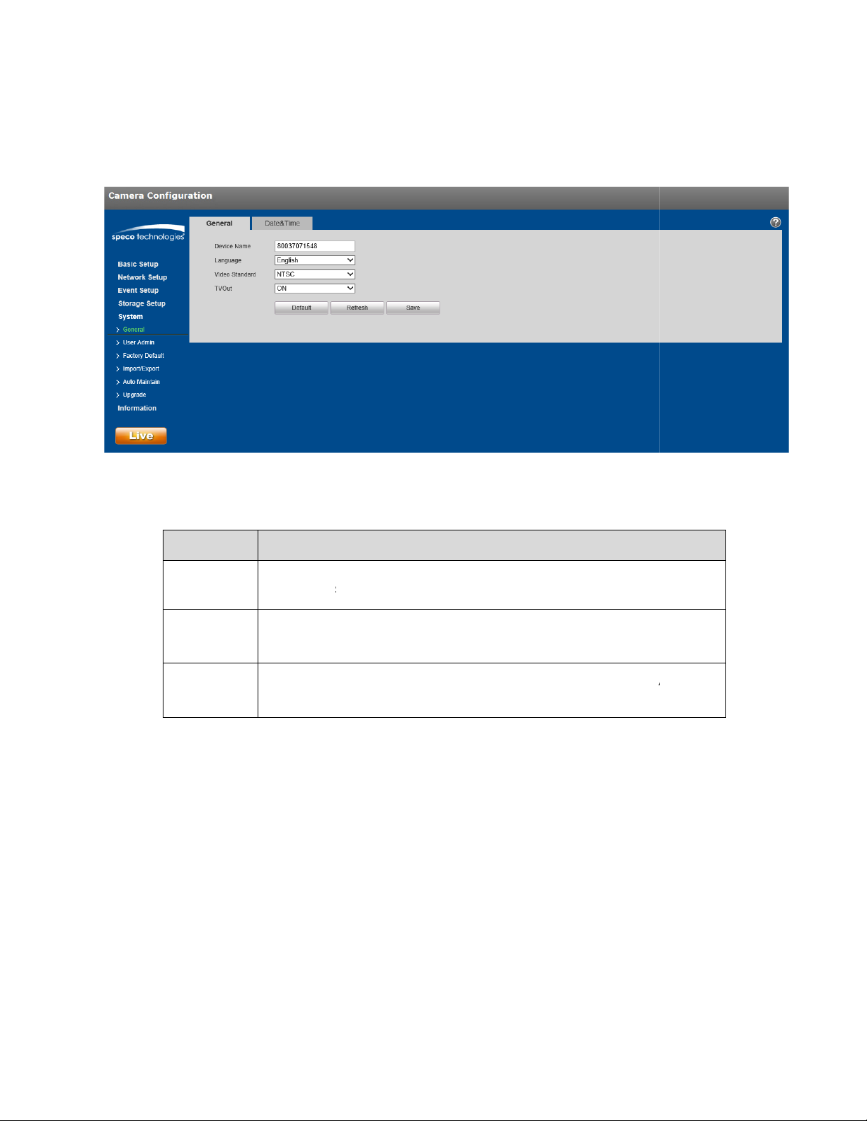
5.5 System
Figure 5
Nickname for the device can be set here. By default, the serial number of
the device is shown.
Displays the video
Some models will have a TV output option. This can be turned on/off.
5.5.1 General
The General interface is shown in
-64.
Figure 5-64
Parameter Function
Device
Name
Video
Standard
TV Out
standard, which is NTSC for North America.
80
Page 85

The Date & T
ime interface is shown as in
Please refer to the following sheet for detailed information.
Select the display format of the date
Select between a 24
Set the
time zone of the device.
Current time of the device. This can be set manually.
this button to save the
the location utilizes Daylight Saving Time (DST), check the Enable box
and set up the start and end times for DST.
heck the box to enable NTP.
S
et the time server address.
Set the
time server port.
How often the device should synchronize the time with the time server.
from the dropdown list.
-
hour display and a 12
-
hour display.
Figure 5-65.
Figure 5-65
Parameter Function
Date format
Time Format
Time zone
Current
Time
Sync PC Click
DST Enable If
Synchronize
with NTP
NTP server
Port
Update
period
C
device time as the PC time.
81
Page 86

, the max
hyphen, dot
Password can be 0~32 characters in number
A specific user can belong to only one group.
66 for the User Name interface.
If enabled, n
back to the login page.
For creating a user and adding the user to a group.
not exceed the
length is 31 characters, which can be made up of
to view the live stream
See
5.5.2 User Admin
For user names and user groups
numbers, letters, underline,
5.5.2.1 User Name
See Figure 5-
imum character
, and @.
s and letters only.
Enable anonymous login:
Logout on the live view page to go
Add user:
Note that a user’s rights cannot
Figure 5-66
o username and password are required
User rights can also be set.
rights of the group.
. Click on
Figure 5-67.
82
Page 87

5.5.2.2 Group
interface is shown as in
The group management
Figure 5-67
Figure 5-68.
83
Page 88

Add group: See Figure 5-69.
the group name and then check the
Enter
Figure 5-68
applicable boxes for the rights of the group.
Figure 5-69
84
Page 89
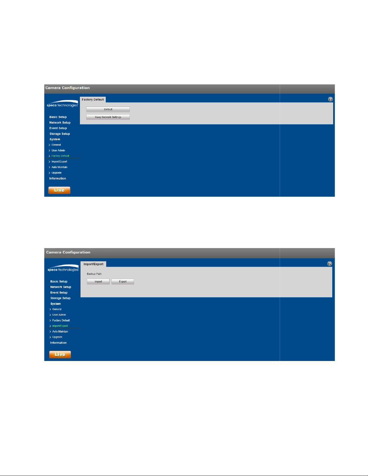
5.5.3 Factory Default
interface is shown in
“Default” option resets every setting of the device while the “Keep Network Settings” option retains
pertinent network setup information of the device.
This can be used to set up multiple devices of the same model with the
The factory default
The
Figure 5-70.
Figure 5-70
5.5.4 Import/Export
The interface is shown in Figure 5-71.
same system configuration.
Figure 5-71
85
Page 90

Parameter Function
Import a configuration file
Export the current configuration of the device to the
Figure 5
(file extension is “.bin”)
to the device
.
local PC.
button to begin
Import
Export
5.5.5 Upgrade
The upgrade interface is shown in
Select the applicable firmware file
firmware update.
-72. Firmware of the device can be updated here.
and then click the Upgrade
the
Figure 5-72
86
Page 91

5.6 Information
Figure 5
In this section, the model number, firmware version and date, serial number of the device, and tech support
74 for the system log interface
Please refer to the following sheet for log parameter information.
5.6.1 Version
The version interface is shown in
contact information are shown.
5.6.2 Log
See Figure 5-
-73.
Figure 5-73
.
Figure 5-74
87
Page 92

Parameter Function
Set the start time of the requested log.
Set the end time of the requested log.
Select the type of information to display.
Select
one item to view detailed information
Can be used to
Figure 5
Information about all users who are currently logged into the device is shown.
This manual is for reference only.
is
All trademarks and registered trademarks mentioned are the properties of their respective
If further explanation is needed, please contact Speco Technolog
about the entry
.
back up log files to
the PC.
the model
.
.
Start time
End time
Type
Log
information
Backup
5.6.3 Online User
The online user interface is shown in
-75.
Note:
All information described here
owners.
Figure 5-75
Slight differences may be found in depending on
subject to change without prior written notice.
ies technical support
.
88
Page 93

Speco Technologies
200 New Highway
Amityville, NY 11701
Phone: 631-957-8700
Email: techsupport@specotech.com
Web: http://www.specotech.com
89
 Loading...