

Page 1
Quick Start Guide
4MP 30X PTZ IP Camera
O4P30X
Version 1.0.1
Page 2

i
Table of Contents
1 DEVICE CHECK AND INSTALLATION ............................................................................ 1
1.1 Installation Requirements ......................................................................................... 1
1.2 Check Accessories ..................................................................................................... 1
1.3 Open the Device ....................................................................................................... 1
1.4 SD Card Installation ................................................................................................... 2
1.5 Reset ........................................................................................................................ 2
1.6 Speed Dome Installation ........................................................................................... 3
1.6.1 Quick Installation port ........................................................................................... 3
1.6.2 Cable Connection ................................................................................................... 3
1.6.3 Install the speed dome .......................................................................................... 4
2 BRACKET DIMENSIONS .............................................................................................. 6
2.1 Wall Mount Bracket .................................................................................................. 6
3 WALL MOUNT INSTALLATION .................................................................................... 7
3.1 Component Installation ............................................................................................. 7
3.2 Installation................................................................................................................ 7
3.2.1 Installation Requirements ...................................................................................... 7
3.2.2 Installation Steps ................................................................................................... 7
4 IP SCANNER .............................................................................................................. 9
4.1 Overview .................................................................................................................. 9
4.2 Operation ................................................................................................................. 9
5 WEB OPERATION .................................................................................................... 10
5.1 Login and Main Interface ......................................................................................... 10
6 APPENDIX
7 APPENDIX
RELATIONSHIP ................................................................................................................ 12
ⅠⅠⅠⅠ
SURGE PROTECTION ............................................................................. 11
ⅢⅢⅢⅢ
24V AC CABLE DIAMETER AND TRANSMISSION DISTANCE
Page 3

ii
8 APPENDIX IV WIRE GAUGE REFERENCE .................................................................... 13
Page 4

iii
Welcome
Thank you for purchasing this Network camera!
This manual is designed to be a reference tool for your system.
Please read this manual carefully before operating the unit and retain it for future reference.
Should you require any technical assistance, please contact Speco Technologies Technical
Support.
Page 5

iv
Important Safeguards and Warnings
1....Electrical safety
All installation and operation here should conform to local electrical safety codes.
Use a certified/listed 12VDC Class 2 power supply only.
Please note: Do not connect two power supplying sources to the device at the same time;
it may result in device damage! The product must be grounded to reduce the risk of
electric shock.
Improper handling and/or installation could run the risk of fire or electrical shock.
2....Environment
Heavy stress, violent vibration or exposure to water is not allowed during transportation,
storage and installation.
This product should be installed in a cool, dry place away from direct sunlight and heat
sources.
Do not install the product in extreme temperature conditions.
Do not expose the camera to electromagnetic radiation. Otherwise it may result in CMOS
sensor failure.
Do not block any ventilation openings.
Do not allow water and liquid intrusion into the camera.
3. Operation and Daily Maintenance
Please shut down the device and then unplug the power cable before you begin any
maintenance work.
Do not touch the CMOS sensor optic component. You can use a blower to clean the dust on
the lens surface.
Always use the dry soft cloth to clean the device. If there is too much dust, use a cloth
dampened with a small quantity of neutral detergent. Finally use the dry cloth to clean the
device.
Please use a professional optical cleaning method to clean the enclosure. Improper
enclosure cleaning (such as using cloth) may result in poor IR functionality and/or IR
reflection.
The grounding holes of the product are recommended to be grounded to further enhance
the reliability of the camera.
Dome cover is an optical device, please don’t touch or wipe cover surface directly during
installation and use, please refer to the following methods if dirt is found:
Stained with dirt
Use oil-free soft brush or hair dryer to remove it gently.
Stained with grease or fingerprint
Use oil-free cotton cloth or paper soaked with alcohol or detergent to wipe from the lens
Page 6

v
center outward. Change the cloth and wipe several times if it is not clean enough.
Warning
This camera should be installed by qualified personnel only.
All the examination and repair work should be done by qualified personnel.
Any unauthorized changes or modifications could void the warranty.
Statement
This guide is for reference only.
Product, manuals and specifications may be modified without prior notice. Speco
Technologies reserves the right to modify these without notice and without incurring any
obligation.
Speco Technologies is not liable for any loss caused by improper operation.
Note:
Before installation, check the package and make sure that all components are included.
Keep the package material in case the camera needs to be sent back for service or repair.
Contact your rep or Speco customer service department immediately if something is broken
or missing in the package.
Page 7

1
1 Device Check and Installation
CD 1
1.1 Installation Requirements
Basic Requirement
All installation and operation here should conform to your local electrical safety codes.
Before installation, please open the package and make sure all components are included.
Please make sure the speed dome installation environment can meet your requirement.
If there is special requirement, please contact your local dealer for more information.
We assume no liability or responsibility for all the fires or electrical shock caused by
improper handling or installation.
1.2 Check Accessories
Before installation, check the package and make sure that all components are included.
Contact your rep or Speco customer service department immediately if something is broken
or missing in the package.
Accessory Name Amount
Network Camera Unit 1
Quick Start Guide 1
Wall Mounting Bracket 1
Installation Accessories Bag 1
1.3 Open the Device
Please open the box and then take out the speed dome.
Remove the bracket component, take out the EPE foam around the module, Figure 1-1.
Page 8

2
Figure 1-1
1.4 SD Card Installation
Remove the bracket component; open the cover and locate the micro-SD card slot on the
module ISP board (see Figure 1-2).
Figure 1-2
1.5 Reset
Locate the reset button on the PTZ mainboard after you remove the bracket component.
See Figure 1-3. Reset button is used to reset the camera back to factory default.
Page 9

3
Figure 1-3
1.6 Speed Dome Installation
1.6.1 Quick Installation port
Now you can install the quick installation port. Please twist Teflon tape around the screw
thread of the quick installation port and turn it into the screw thread of the wall mount
bracket. Use M4 stainless screws to secure firmly. See Figure 1-4.
Figure 1-4
1.6.2 Cable Connection
Connect the safety hook of the intelligent speed dome cover to the hook of the quick
installation port.
Page 10

4
Connect the necessary cables.
1.6.3 Install the speed dome
Step 1
Pull the cable to the wall mount bracket slowly.
Step 2
Line up the straight edge of the flange of the speed dome to the straight edge of the quick
installation port, and then push the speed dome to the bottom of the port slowly.
Step 3
Use your hands to turn the quick installation port M6*14 stainless screw (with spring washer)
to the Ф6.5 hole of the straight edge of the speed dome. Turn other two M6*14 stainless
screws to groove of speed dome flange. Use the inner hex tool to fix these three stainless
screws. Now you have completed the installation. See Figure 1-5.
Figure 1-5
Step 4
Please make sure:
The three stainless screws of the quick installation port are firmly secured.
The speed dome is fixed.
The speed dome is straight.
The safety hook connection is firm.
After your installation, the interface is shown as in Figure 1-6.
Page 11

5
Figure 1-6
Page 12

6
2 Bracket Dimensions
2.1 Wall Mount Bracket
The wall mount bracket dimensions are shown as below. See Figure 2-1.
Figure 2-1
Page 13

7
3 Wall Mount Installation
3.1 Component Installation
Wall mount bracket is shown as below. See Figure 3-1.
Figure 3-1
3.2 Installation
3.2.1 Installation Requirements
The wall mount speed dome can be installed on a hard surface wall. Before the installation,
please make sure:
The wall is thick enough to install the expansion bolt.
The wall can at least sustain the 8x weight of the speed dome, bracket and the
accessories.
3.2.2 Installation Steps
Step 1
See Figure 3-2. Please draw four holes position in the wall according to the hole of the
bottom of the wall mount bracket. Use four hex bolts and flat washer to fix the bracket in
the expansion bolts.
Page 14

8
Figure 3-2
Step 2
Install the speed dome on the bracket. See Figure 3-3. Please refer to section 1.6 Speed
Dome Installation for more details.
Figure 3-3
Page 15

4 IP Scanner
IP Scanner can search for the device on the local network.
Please note that only devices that are on the same subnet can be discovered.
st, you can view the IP address, model number, and MAC address of each
device. Select the applicable device and double click to open up the web viewer.
9
4.1
Overview
4.2 Operation
Open up IP Scanner.
Figure 4-1
In the device li
Figure 4-1 IP Scanner
Page 16

5 Web Operation
This device supports viewing and management via a web browser on
Login and Main Interface
Open the browser and input network camera address in the address bar or double click the
Figure 5
The login interface is shown as below. See
Please input your user name and password.
and password is
Note: For security purposes, please change the password after initial login.
10
address
here
a PC.
5.1
device in IP Scanner. See
-1.
Input your IP
Default user name is
admin
Figure 5-1 IP address
Figure 5-2.
Figure 5-2 Web login
1234
.
Page 17
11
6 APPENDIX ⅠⅠⅠⅠ Surge Protection
This device uses TVS lighting protection technology. It can effectively prevent damages from
various pulse signals below 2000W, such as sudden lighting and surge. While maintaining
your local electrical safety code, you still need to take necessary precaution measures when
installing the speed dome in an outdoor environment.
The distance between the signal transmission cable and high-voltage device (or high-
voltage cable) shall be at least 50 meters (164 ft).
Outdoor cable layout shall go under the penthouse if possible.
For vast land, please use sealing steel tube under the land to implement cable layout
and connect one point to the earth. Open floor cable layout should not be used.
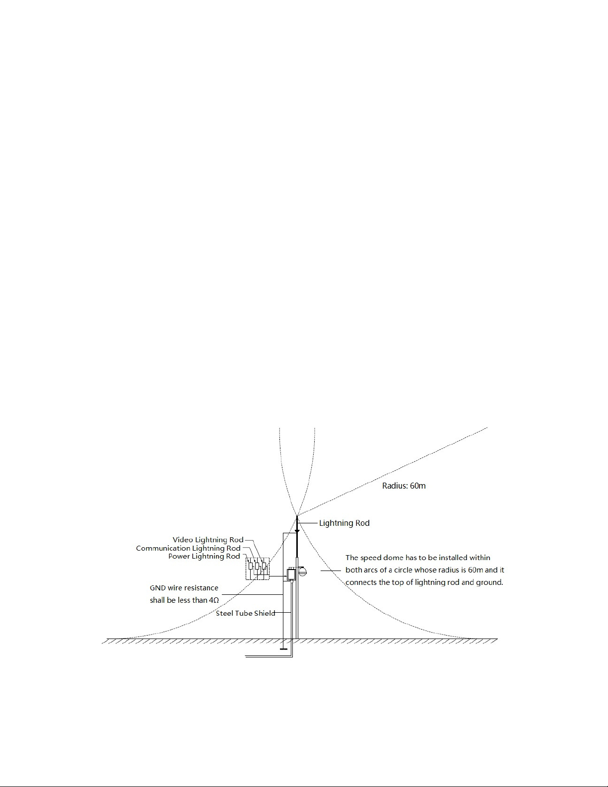
In areas prone to strong thunderstorms or near high sensitive voltage (such as near
high-voltage transformer substation), you need to install additional high-power
lightning protection device or lightning rod.
The lightning protection and earth of the outdoor device and cable shall be considered
under the lightning protection of the whole building and conform to your local national
or industry standard.
System shall adopt equal-potential wiring. The earth device shall meet anti-jamming
and at the same time conform to your local electrical safety code. The earth device shall
not short circuit to N (neutral) line of high voltage power grid or mixed with other wires.
When connecting the system to earth alone, the earth resistance shall not be more than
4Ω and earth cable cross-sectional area shall be below 25 mm^2. See Figure 6-1
.
Figure 6-1
Page 18

12
7 APPENDIX ⅢⅢⅢⅢ 24V AC Cable Diameter and Transmission
mm
488.52
763.31
1192.67
3053.25
244.26
381.66
596.34
1526.62
162.84
254.44
397.56
1017.75
122.13
190.83
298.17
763.31
152.66
238.53
610.65
127.22
198.78
508.87
109.04
170.38
436.18
149.08
381.66
132.52
339.25
119.27
108.42
Distance Relationship
It is the recommended transmission distance when the cable diameter is fixed and the 24V
AC power consumption is below 10%. For the AC device, the max permission voltage power
consumption is 10%. For example, when a device of rated power 20W installed from the
transformer 141 inches (42m), then the min cable diameter is 0.8000mm.
Feet(m)
w
5
10
15
20
25
30
35
40
45
50
0.8000 1.000 1.250 2.000
(
148.90)
(
74.45)
(
49.63)
(
37.23)
97.70(29.78)
81.42(24.82)
69.79(21.27)
61.06(18.61) 95.41(29.08)
54.28(16.54) 84.81(25.85)
48.85(14.89) 76.33(23.27)
(
232.66)
(
116.33)
(
77.55)
(
58.16)
(
46.53)
(
38.78)
(
33.24)
(
363.53)
(
181.76)
(
121.18)
(
90.88)
(
72.71)
(
60.59)
(
51.93)
(
45.44)
(
40.39)
(
36.35)
(
(
(
(
(
(
(
(
(
305.32(93.06
930.63)
465.31)
310.21)
232.66)
186.13)
155.10)
132.95)
116.33)
103.40)
)
55
60
65
70
75
80
85
90
95
100
44.41(13.54) 69.39(21.15)
40.71(12.41) 63.61(19.39) 99.39(30.29) 254.44(77.55
37.58(11.45) 58.72(17.90) 91.74(27.96) 234.87(71.59
34.89(10.64) 54.52(16.62) 85.19(25.97) 218.09(66.47
32.57(9.93) 50.89(15.51) 79.51(24.24) 203.55(62.04
30.53(9.31) 47.71(14.54) 74.54(22.72) 190.83(58.16
28.74(8.76) 44.90(13.69) 70.16(21.38) 179.60(54.74
27.14(8.27) 42.41(12.93) 66.26(20.20) 169.62(51.70
25.71(7.84) 40.17(12.25) 62.77(19.13) 160.70(48.98
24.43(7.45) 38.17(11.63) 59.63(18.18) 152.66(46.53
(
33.05)
277.57(84.60
)
)
)
)
)
)
)
)
)
)
Page 19

13
8 APPENDIX IV Wire Gauge Reference
Metric bare wire
AWG
SWG Bare wire cross section
0.050
43 47
0.00196
0.060
42 46
0.00283
0.070
41 45
0.00385
0.080
40 44
0.00503
0.090
39 43
0.00636
0.100
38 42
0.00785
0.110
37 41
0.00950
0.130
36 39
0.01327
0.140
35 0.01539
0.160
34 37
0.02011
0.180
33 0.02545
0.200
32 35
0.03142
0.230
31 0.04115
0.250
30 33
0.04909
0.290
29 31
0.06605
0.330
28 30
0.08553
0.350
27 29
0.09621
0.400
26 28
0.1257
0.450
25 0.1602
0.560
24 24
0.2463
0.600
23 23
0.2827
0.710
22 22
0.3958
0.750
21 0.4417
0.800
20 21
0.5027
0.900
19 20
0.6362
1.000
18 19
0.7854
1.250
16 18
1.2266
1.500
15 1.7663
2.000
12 14
3.1420
2.500
4.9080
3.000
7.0683
diameter
(mm)
2
(
mm
)
 Loading...