

Page 1
Quick Start Guide
O4D6M
Page 2

Warning and Caution
1
■ If the p rod uct d oes not work properly, plea se conta ct your
dealer or the nearest service center. Never attempt to disassemble
the camera yourself. Any unauthorized changes or modifications
could void the warranty.
■ Do not allow water or liquid intrusion into the camera.
■ All installation and operation here should conform to local
electrical safety codes. Make sure the device is firmly installed
on the wall or ceiling.
■ Do not use camera beyond specified voltage range.
■ Do not drop the camera or subject it to physical shock.
■ Avoid touching the camera lens.
■ If cleaning is necessary, please use cleaning cloth to wipe it
gently.
■ Do not aim the c amera at the sun or e xtrem ely brig ht light
sources.
■ Do not place the camera in extremely hot or cold environments
and d u sty a n d damp l ocati o n s. Do n ot ex p ose it to hi g h ly
electromagnetic radiation.
■ Do not block any ventilations.
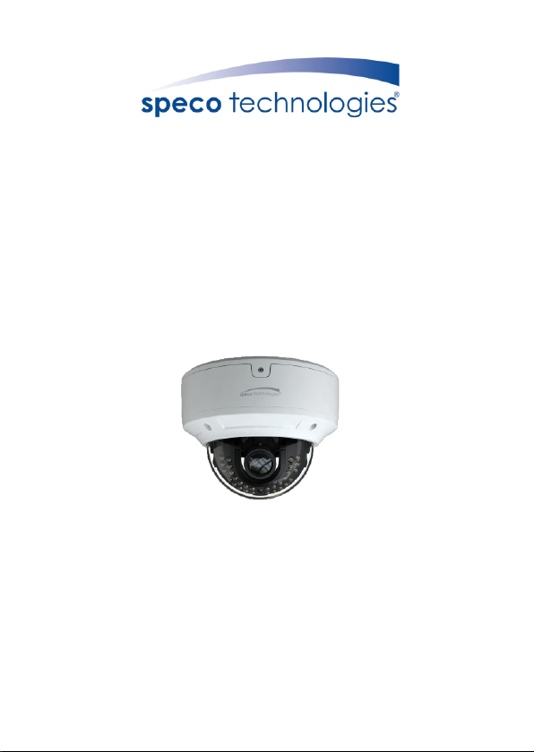
Package
2
Page 3
Camera
Quick start guide
4 tappi ng screws PA 4×25
CD
Screwdriver
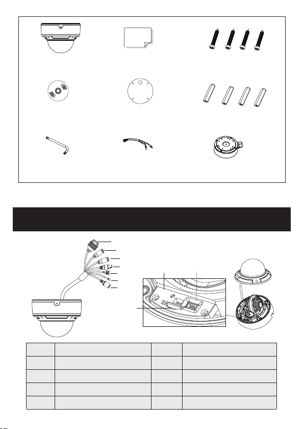
Overview
Overview
3
3
1
Ethernet connector
MIC input (3.5mm)
2
Line out (3.5mm)
3
Analog ouput (BNC)
4
Alarm input/output
5
Drill template
CVBS&DC
IN cables
1
2
3
4
5
6
7
8
Plastic plug ×4
Junction box
9
R
ES
TF
6
7
8
9
10
10
E
T
LINK
DC
IN
C
VB
S
RS485 cable
DC power connector
Micro SD card slot
Reset hole
CVBS/DC IN port for testing
Page 4

p
a
y C
it
r
cu
Se
ALM -COM
ALM -NO
ALM -IN
RS4 85T+
RS4 85T-
ALM -GND
* 1 It is recom mend ed to install th e secur ity cap for outd oor installations.
* 2 DC 12V pow er su ppl y is no t require d if a Po E swi tch o r injector is us ed to p owe r
the camera.
► Connecting Network Cable
1
2
3
① Loosen th e nut from th e main element.
② Run the net work cabl e (without RJ 45 connector) through both
element s. Then crimp the cable with RJ 45 connector.
③ Connect t he cable to the hermetic connector. Then tighte n the nut
and the mai n cover.
Page 5

Installation
4
* Befor e you start, p lease make s ure tha t the w all or ce iling is str ong enough
to with stand thre e times the we ight of t he ca mera.
① Open the up per cover o f the junction box. Then install junction
box onto th e wall by usi ng the scre ws provided.
Upper Cover
② Route the c ables thr ough the cable hole (take side conduit cabling
for examp le). Then reinstall the upper cover to the junction box.
Page 6

③ Loosen th e screws to o pen the lower dome and then loosen the
lock scre w to remove t he mounting base.
Lock Sc rew
Mount ing B ase
Lower D ome
④ Install t he mounti ng base onto the junction box. Then connect the
cables an d fix the dom e to the mounting base with the lock screw.
Page 7

⑤Three-axis Adjustment-Before adjustment, preview the image of the
camera on a monitor and then adjust the camera according to the figure
below to get an optimum angle.
Tilt 0° ~77 °
Pan 0°~ 360 °
Rotat ion 0 °~360°
⑥ Install the lower dome back to the camera and fix it with the screws.
Web Operation and Login
5
IP Scanner can search for the devi ce on the local network.
● Operation
① Make sure that the camera and the PC are connected to the same
local network. The camera is set to DHCP by default.
② Install IP Scanner from the CD and r un it after installation.
Page 8

③ In the device list, you can view the IP address, model number, and
MAC addre ss of each de vice. Sel ect the applicable device and double
click to open up the web viewer. You can also manually enter t he IP
address i n the addre ss bar of the w eb browse r.
The login i nterfac e is shown above. Default user name is admin a nd
passw ord is 1234. Afte r l ogg ing in , f oll ow dir ect io ns t o in stall
applica ble plugi ns.
 Loading...