

Page 1
i
Quick Start Guide
4MP Vandal Dome IP Camera
O4D2M
Page 2

ii
Welcome
Thank you for purchasing this network camera!
This owner’s manual is designed to be a reference tool for your system.
Please read this manual carefully before operating the unit and retain it for future reference.
Should you require any technical assistance, please contact Speco Technologies Technical Support.
Page 3

iii
Important Safeguards and Warnings
1
....
Electrical safety
All installation and operation here should conform to local electrical safety codes.
Use a certified/listed 12VDC Class 2 power supply only.
Please note: Do not connect two power supplying sources to the device at the same time; it may result in
device damage! The product must be grounded to reduce the risk of electric shock.
Improper handling and/or installation could run the risk of fire or electrical shock.
2
....
Environment
Heavy stress, violent vibration or exposure to water is not allowed during transportation, storage and
installation.
This product should be installed in a cool, dry place away from direct sunlight and heat sources.
Do not install the product in extreme temperature conditions.
Do not expose the camera to electromagnetic radiation. Otherwise it may result in CMOS sensor failure.
Do not block any ventilation openings.
Do not allow water and liquid intrusion into the camera.
3. Operation and Daily Maintenance
Please shut down the device and then unplug the power cable before you begin any maintenance work.
Do not touch the CMOS sensor optic component. You can use a blower to clean the dust on the lens surface.
Always use the dry soft cloth to clean the device. If there is too much dust, use a cloth dampened with a small
quantity of neutral detergent. Finally use the dry cloth to clean the device.
Please use a professional optical cleaning method to clean the enclosure. Improper enclosure cleaning (such as
using cloth) may result in poor IR functionality and/or IR reflection.
The grounding holes of the product are recommended to be grounded to further enhance the reliability of the
camera.
Dome cover is an optical device, please don’t touch or wipe cover surface directly during installation and use,
please refer to the following methods if dirt is found:
Stained with dirt
Use oil-free soft brush or hair dryer to remove it gently.
Stained with grease or fingerprint
Use oil-free cotton cloth or paper soaked with alcohol or detergent to wipe from the lens center outward.
Change the cloth and wipe several times if it is not clean enough.
Warning
This camera should be installed by qualified personnel only.
All the examination and repair work should be done by qualified personnel.
Any unauthorized changes or modifications could void the warranty.
Page 4

iv
Statement
This guide is for reference only.
Product, manuals and specifications may be modified without prior notice. Speco Technologies reserves the
right to modify these without notice and without incurring any obligation.
Speco Technologies is not liable for any loss caused by improper operation.
Note:
Before installation, check the package and make sure that all components are included.
Contact your rep or Speco customer service department immediately if something is broken or missing in the
package.
Accessory Name Amount
Network Camera Unit 1
Quick Start Guide 1
Installation Accessories Bag 1
CD 1
Page 5

v
Table of Contents
1 Structure ................................................................................................................................. 1
1.1
Port Description .......................................................................................................... 1
1.2
Dimensions ................................................................................................................. 2
1.3
Bidirectional Audio ..................................................................................................... 2
1.3.1 Device-end to PC-end ........................................................................................... 2
1.3.2 PC-end to Device-end ........................................................................................... 2
1.4
Alarm Setup ................................................................................................................ 3
2 Device Installation ................................................................................................................... 5
2.1
Installation Steps ........................................................................................................ 5
2.2
Micro SD Card Installation........................................................................................... 7
3 IP Scanner ............................................................................................................................... 8
3.1
Operation ................................................................................................................... 8
4 Web Operation ........................................................................................................................ 9
4.1
Login and Main Interface ............................................................................................ 9
Page 6

1
1 Zoom W
-
Adjust
s lens to
wide angle end (image min zoom)
2 RESET
Reset button
Restore
s device
to
factory default.
Analog output video
signal, able to
5 Micro SD
Micro SD slot
Micro SD
for local storage
Include
s alarm input/
output and audio input
/
Connect
s to standard Ethernet
1 Structure
1.1 Port Description
You can refer to the following figure for more details. See Figure 1-1
.
Figure 1-1
Please refer to the following sheet for detailed information.
SN Port Port Name Function Description
3 Zoom T - Adjusts lens to telephoto end (image max zoom)
4 VIDEO_OUT -
6 I/O I/O port
7 LAN Network port
8 POWER Power input port Power port, input DC12V
connect to test monitor to view image.
output.
Supports POE function
Page 7

2
1.2 Dimensions
Please refer to the following figure for dimension information. The unit is mm. See Figure 1-2
Figure 1-2
1.3 Bidirectional Audio
1.3.1 Device-end to PC-end
Device Connection
First, connect a microphone to the audio input port of the device. Then connect a speaker to the audio output
port of the PC. Log in to the web viewer’s live view page and then click the microphone button on the top right
corner to enable the bidirectional audio function.
1.3.2 PC-end to Device-end
Device Connection
Enable microphone input on the PC. Then connect a speaker to the audio output port of the device. Log in to
the web viewer’s live view page and then click the microphone button on the top right corner to enable the
bidirectional audio function.
Page 8

1.4 Alarm Setup
Step 1 Connect alarm input device to the alarm input
Step 2 Connect alarm output device to the alarm output
esistor to 3.3V externally.
, set alarm input and output correspondingly.
Please refer to the following figure for alarm input information. See Figure
Alarm input: When the input signal is idle or grounded, the device
alarm input port. When the input signal is connected to 3.3V or
the input signal is grounded, the device collects the logic “0”.
Please refer to the following figure for alarm output information. See Figure
larm output is collector open circuit output
can collect the different statuses of the
idle, the device collects the logic “1”. When
5 and Figure 1
Alarm input, output description:
which connects 10K r
Step 3 Open the web viewer
Figure 1-3
port.
port. A
1-4.
is
Figure 1-4
1-
-6.
Page 9

4
Figure 1-5
Figure 1-6
Mode A: Level application. Alarm output high and low level, alarm output is OC; it needs to increase pull-up
resistance externally to work normally. Max external pull-up level is 5V, max port current is 5mA. After external
pull-up resistance is increased, the default of output signal is high level (external pull-up voltage), and it
switches to low level when there is alarm output (when the working current is 5mA, output voltage is less than
0.8V).
Mode B: Switch application. Alarm output is used to drive external circuit, max current is 30mA, max voltage is
5V, it is advised to add a relay if it is beyond the value.
Page 10

5
2 Device Installation
Note:
Before installation, please make sure the installation surface can support a minimum of 3 times the weight
of the camera
2.1 Installation Steps
Figure 2-1
Please follow the steps listed below to install the device. Please refer to Figure 2-1 for reference.
Step 1
Use star-shaped wrench in the accessories bag to unscrew the three star-shaped screws on the dome enclosure,
and then open the dome enclosure.
Step 2
Please take out the installation position template in the accessories bag, and then paste it on the ceiling or the
wall where you wish to install the camera.
Step 3
Find the “cross” signs on the template, and drill three holes on the installation surface for the expansion bolts
and then insert the expansion bolts into the holes. Secure these bolts firmly.
Step 4
Adjust the device installation pedestal to the proper position and then pull cable through the exit hole on the
installation surface. Line up the three screw holes in the device pedestal to the three plastic expansion bolt
holes. Put the installation screws into the plastic expansion bolts and secure them firmly. Fix the pedestal on
the installation surface.
Step 5
Adjust the lens to the desired angle.
Hold the screw location of the rotation bracket on both sides, turn the rotation bracket horizontally, adjust the
lens direction horizontally to the targeted position; unscrew the two locking screws on both sides (do not
remove them completely, just make them loose), hold the IR light decoration cover to make the lens rotate
vertically, adjust the vertical direction of lens to a proper monitoring angle, then tighten the locking screws on
Page 11

6
both sides; Hold the IR light decoration cover to rotate horizontally, adjust the image and adjust the lens
horizontal direction to the targeted location; Range of adjusting lens angle: vertical rotation direction (0°
+65°), horizontal rotation direction (0°~+355°), image horizontal rotation direction (0°~+355°).
Step 6
Take up the dome enclosure; aim the location of side cable exit and cover the enclosure, use the hex wrench to
secure the dome screws firmly.
Cable Connection
The device has two wiring holes and supports pins with a diameter of less than 15mm to pass through.
The device is equipped with two waterproof sealing plugs for the holes. The plug supports cables a diameter
between 4.0mm ~ 6.0mm to pass through.
Please refer to the following steps for the exact use:
Step 1
Take out the waterproof sealing plug, and pull the cable with 4.0mm~6.0mm diameter through the sealing plug
according to the direction shown in the following figure.
~
Figure 2-2
Figure 2-3
Step 2
Before step 4 of device installation, install the cable with waterproof sealing plug on the pedestal through the
installation hole under the device pedestal, and assemble the cable pin.
Step 3
Connect the pin to the device and install the device according to the normal steps.
Page 12
7
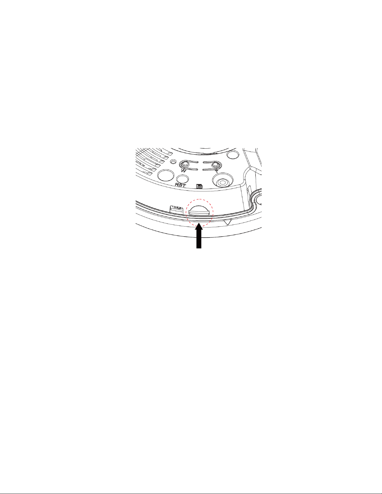
2.2 Micro SD Card Installation
Note:
Please shut down the device before you install a Micro SD card.
Step 1
Open the device enclosure according to the step 1 in the device installation.
Step 2
Find the “Micro SD” slot in the device; adjust the direction of Micro SD card according to the direction
shown on the device and insert the card into the slot.
Figure 2-4
Page 13
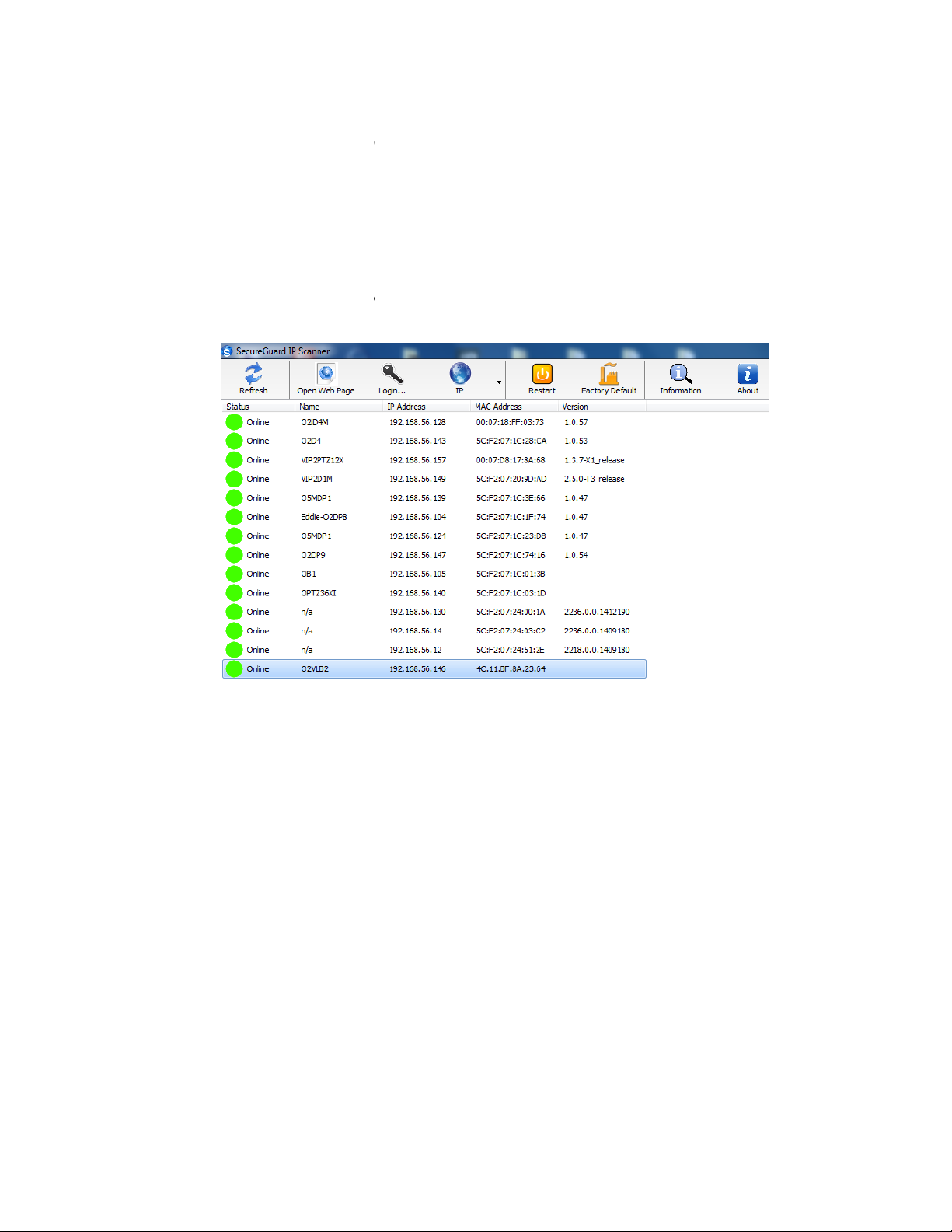
3 IP Scanner
IP Scanner can search for the device on the local network.
Please note that only devices that are on the same subnet can be discovered.
The device is set to DHCP mode by default.
Error! Reference source not found.
In the device list, you can view the IP address, model number, and MAC address of each device. Select the
to open up the web viewer.
3.1 Operation
Open up IP Scanner.
applicable device and double click
Figure 3-1
Page 14
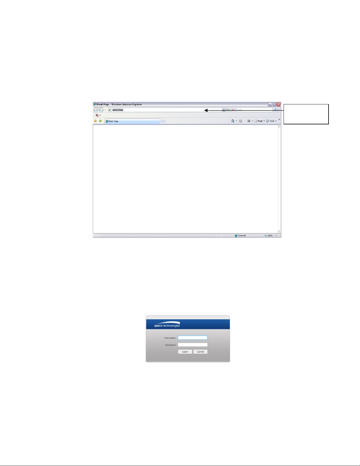
4 Web Operation
This device supports viewing and management via a web browser on a PC.
Login and Main Interface
Open the browser and input network camera address in the address bar or double click the device in IP S
The login interface is shown as below. See
Please input your user name and password.
and password is
ote: For security purposes, please change the password after initial login.
After logging in, follow directions to install applicable plugins.
address
here
4.1
See Figure 4- 1.
canner.
Input your IP
Default user name is
N
admin
Figure 4- 1 IP address
Figure 4- 2.
1234
.
Figure 4- 2 Web login
 Loading...