

Page 1

User Manual
2MP IP Camera
O2VLB7 / O2VLB8 / O2VLD7 / O2VLD8
Please read this manual carefully before operating the unit and keep it for further reference
Page 2

IP Camera User Manual
Important Safeguards and Warnings
1....Electrical safety
All installation and operation here should conform to local electrical safety codes.
Use a certified/listed 12VDC Class 2 power supply only.
Please note: Do not connect two power supplying sources to the device at the same time; it may result in device damage! The
product must be grounded to reduce the risk of electric shock.
Improper handling and/or installation could run the risk of fire or electrical shock.
2....Environment
Heavy stress, violent vibration or exposure to water is not allowed during transportation, storage and installation.
This product should be installed in a cool, dry place away from direct sunlight and heat sources.
Do not install the product in extreme temperature conditions.
Do not expose the camera to electromagnetic radiation. Otherwise it may result in CMOS sensor failure.
Do not block any ventilation openings.
Do not allow water and liquid intrusion into the camera.
3. Operation and Daily Maintenance
Please shut down the device and then unplug the power cable before you begin any maintenance work.
Do not touch the CMOS sensor optic component. You can use a blower to clean the dust on the lens surface.
Always use the dry soft cloth to clean the device. If there is too much dust, use a cloth dampened with a small quantity of neutral
detergent. Finally use the dry cloth to clean the device.
Please use a professional optical cleaning method to clean the enclosure. Improper enclosure cleaning (such as using cloth) may result
in poor IR functionality and/or IR reflection.
The grounding holes of the product are recommended to be grounded to further enhance the reliability of the camera.
Dome cover is an optical device, please don’t touch or wipe cover surface directly during installation and use, please refer to the
following methods if dirt is found:
Stained with dirt
Use oil-free soft brush or hair dryer to remove it gently.
Stained with grease or fingerprint
Use oil-free cotton cloth or paper soaked with alcohol or detergent to wipe from the lens center outward. Change the cloth and wipe
several times if it is not clean enough.
Page 3

IP Camera User Manual
Warning
This camera should be installed by qualified personnel only.
All the examination and repair work should be done by qualified personnel.
Any unauthorized changes or modifications could void the warranty.
Statement
This guide is for reference only.
Product, manuals and specifications may be modified without prior notice. Speco Technologies reserves the right to modify these
without notice and without incurring any obligation.
Speco Technologies is not liable for any loss caused by improper operation.
Regulatory Information
1.1 FCC conditions
This device complies with part 15 of the FCC Rules. Operation is subject to the following two conditions:
This device may not cause harmful interference
This device must accept any interference received, including interference that may cause undesired operation.
1.2 FCC compliance
This equipment has been tested and found to comply with the limits for a digital device, pursuant to part 15 of the FCC Rules. These
limits are designed to provide reasonable protection against harmful interference. This equipment generate, uses and can radiate
radio frequency energy and, if not installed and used in accordance with the instruction manual, may cause harmful interference to
radio communication. However, there is no guarantee that interference will not occur in a particular installation. If this equipment
does cause harmful interference to radio or television reception, which can be determined by turning the equipment off and on, the
user is encouraged to try to correct the interference by one or more of the following measures:
Reorient or relocate the receiving antenna.
Increase the separation between the equipment and receiver.
Connect the equipment into an outlet on a circuit different from that to which the receiver is connected.
Note:
Before installation, check the package and make sure that all components are included.
Contact your rep or Speco customer service department immediately if something is broken or missing in the package.
::::
::::
Accessory Name Amount
Network Camera Unit 1
Quick Start Guide 1
Installation Accessories Bag 1
CD 1
Page 4

IP Camera User Manual
Table of Contents
Regulatory Information ...................................................................................................................................................................................... 3
1 Introduction ................................................................................................................................................................................................ 1
Welcome .............................................................................................................................................................................................................. 1
2 Web Access and Login .............................................................................................................................................................................. 2
2.1 LAN ........................................................................................................................................................................................................................................ 2
3 Live View ..................................................................................................................................................................................................... 3
4 Camera Configuration ................................................................................................................................................................................ 4
4.1 System Configuration ............................................................................................................................................................................................................. 4
4.1.1
4.1.2
4.1.3
4.2 Display Configuration .............................................................................................................................................................................................................. 5
4.2.1
4.2.2
4.2.3
4.2.4
4.2.5
4.3 Network Setup ........................................................................................................................................................................................................................ 8
4.3.1
4.3.2
4.3.3
4.3.4
4.3.5
4.3.6
4.3.7
4.4 Motion Setup ........................................................................................................................................................................................................................ 12
4.4.1
4.5 Device Log ........................................................................................................................................................................................................................... 12
4.5.1
4.6 Advanced Configuration ........................................................................................................................................................................................................ 13
4.6.1
4.6.2
4.6.3
Appendix ........................................................................................................................................................................................................... 14
Appendix 1 Troubleshooting ........................................................................................................................................................................... 14
System Information ................................................................................................................................................................................................. 4
Date and Time ......................................................................................................................................................................................................... 4
Users ...................................................................................................................................................................................................................... 5
OSD ........................................................................................................................................................................................................................ 5
Image Configuration ................................................................................................................................................................................................ 6
Privacy Mask ........................................................................................................................................................................................................... 6
Video Stream Setup ................................................................................................................................................................................................ 7
Path (Local Recording) ............................................................................................................................................................................................ 7
Network ................................................................................................................................................................................................................... 8
Email ....................................................................................................................................................................................................................... 8
DDNS...................................................................................................................................................................................................................... 9
IP Filter ................................................................................................................................................................................................................... 9
RTSP .................................................................................................................................................................................................................... 10
FTP ....................................................................................................................................................................................................................... 10
SNMP ....................................................................................................................................................................................................................11
Motion Detection ................................................................................................................................................................................................... 12
Log ........................................................................................................................................................................................................................ 12
Firmware Update ................................................................................................................................................................................................... 13
Factory Default ...................................................................................................................................................................................................... 13
Auto Reboot .......................................................................................................................................................................................................... 13
Page 5

IP Camera User Manual
1 Introduction
Welcome
Thank you for purchasing this network camera!
Please read this manual carefully before operating the unit and retain it for future reference.
Should you require any technical assistance, please contact Speco Technologies Technical Support.
Main Features
Built-in PoE (Power over Ethernet)
Integrated IR LEDs for clear vision in low light
IP66 rated for outdoor installations
Remote viewing support via web browser, mobile app, and VMS
1
Page 6
IP Camera User Manual
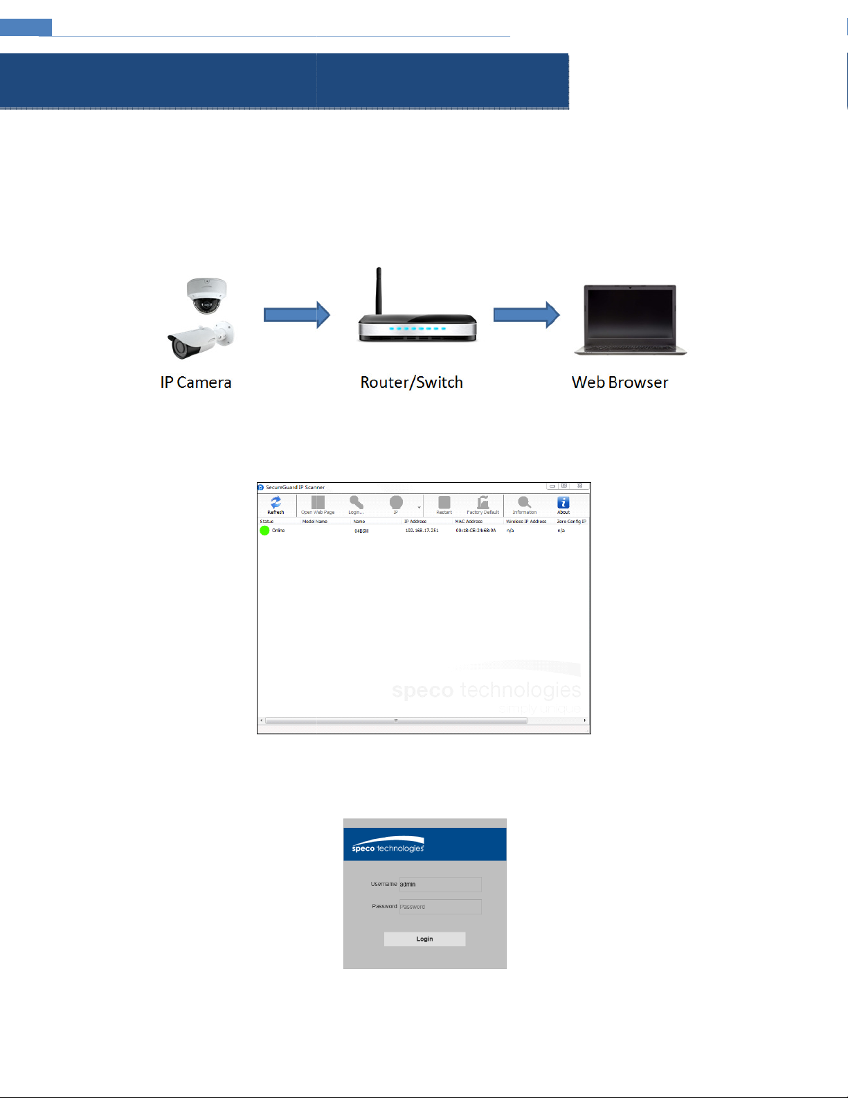
web browser through the LAN
that the camera and the PC are connected
address by the DHCP server. Make sure that the local network has a DHCP server. Routers typically have a DHCP server built in
Install IP Scanner from the CD and run it after installation.
In the device list, the IP address, model number, and MAC address of each device
the web viewer. You can also manually enter the IP address in the address bar of the web browser.
The login interface is shown above. Default user name is admin and password is 1234. After logging in, follow directions to i
DHCP by default and will be assigned an IP
IP Scanner is the tool for discovering the IP cameras on the local network.
. Select the applicable device and double click to open
2 Web Access and Login
The IP camera settings can be accessed via a
2.1 LAN
Access through IP Scanner
Network connection:
.
① Make sure
②
③
up
on the same local network. The camera is set to
will be listed
.
viewing video.
2
nstall applicable plug-ins for
Page 7

IP Camera User Manual
Description
Go to camera setup
Stop/Start
View in stretched format
Start local recording
Digital zoom
een mode, to exit, double click on the mouse or press the ESC key on the keyboard
3 Live View
The window below will be shown after logging in.
The following table describes the icons on the live view
Icon
In full scr
interface.
Icon Description
live view
Adjust image settings
View in original aspect ratio
View in full screen
Generate snapshot
.
3
Page 8

IP Camera User Manual
configuration interface.
o save
information of the
. Please refer to the following interface.
DST: If daylight saving time is utilized in the current time
NTP: If enabled, the device will synchronize the time with a time server. Select the applicable time zone before synchronizat
4 Camera Configuration
Press the “Setup” button to go to the
Note: Wherever applicable, press the “Save” button t
4.1 System Configuration
4.1.1 System Information
In the “System Information” interface, the system
the settings.
device is listed.
4.1.2 Date and Time
To set the time and date, go to SystemGeneral
Select an option to set the time and date.
Synchronize: Sets the device time same as the PC.
zone, use this option to set the parameters.
ion.
4
Page 9

IP Camera User Manual
Other than admin, up to 6 additional users can be configured, with customizable access levels.
Setup
North America uses 60Hz for flicker control. Enable Name and Time to show the camera name and time on the screen. C
4.1.3 Users
To configure users, go to System -> Users.
4.2 Display Configuration
Display Configuration includes Image settings, Stream
4.2.1 OSD
Go to DisplayLive as shown below.
, OSD, Privacy Mask, and local recording path setup.
the settings.
5
lick the “Save” button to save
Page 10
IP Camera User Manual
, various settings can be adjusted such as
Choose between Auto, Color Mode, and monochrome Mode
Sets the delay in how long the camera waits before switching to color or
: if enabled, the auto exposure will activate according to the scene so that the object of
Compensates for a contrast in the scene between light and dark areas.
djust the color temperature according
Choose between auto shutter speed and manual.
Use for manual shutter speed adjustment
Used to try to clear up a foggy image.
shown below.
drag the mouse to draw the zones.
privacy mask zones, click to choose each zone and click the “Delete” button.
saturation
monochrome when light level changes
Typically used in a lobby where the camera is pointing towards the
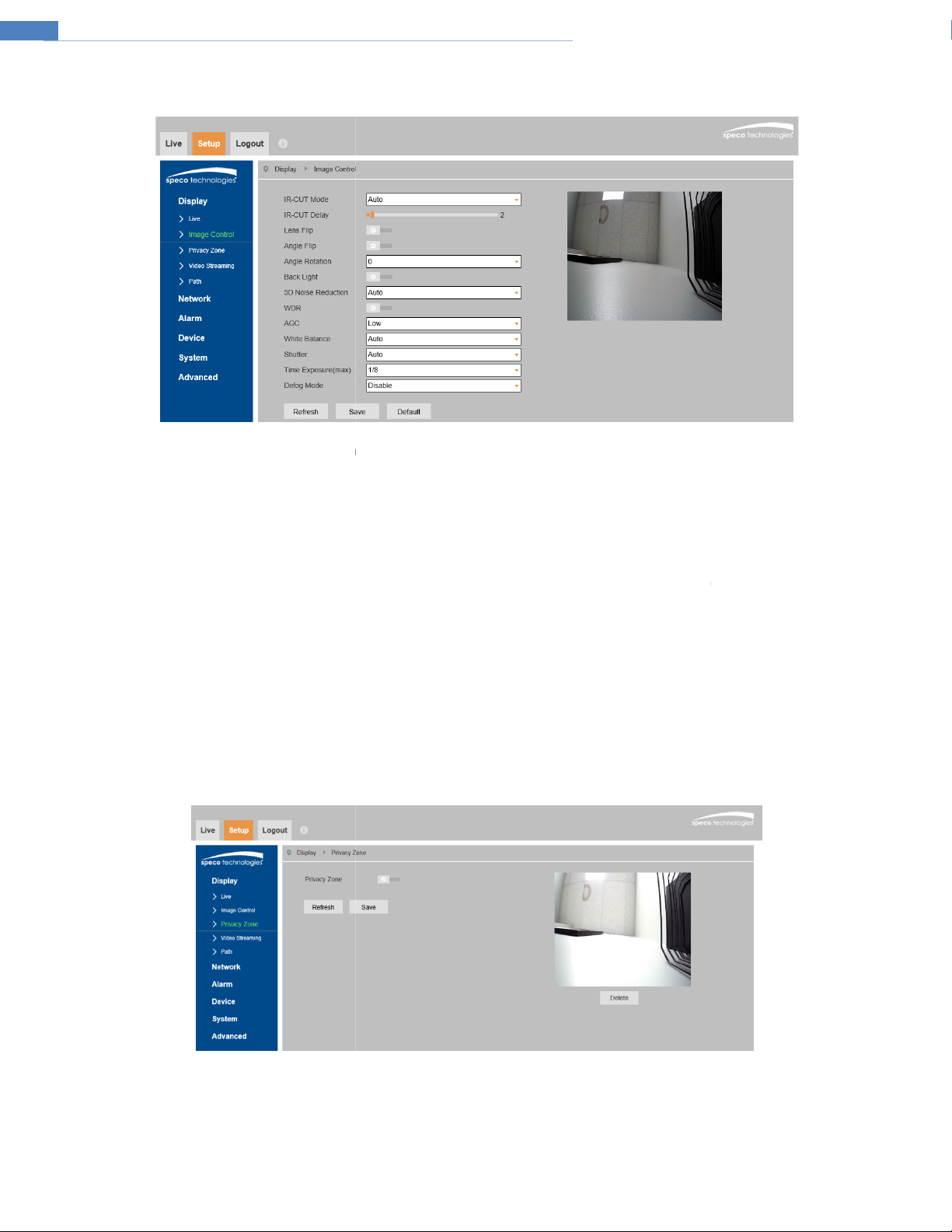
4.2.2 Image Configuration
In the Image Control interface shown below
brightness, contrast, hue,
, etc.
IR-Cut Mode:
IR-Cut Delay:
mode is set to Auto.
Lens Flip / Angle Flip: Horizontal and vertical flip.
Backlight Compensation (BLC)
be seen clearly.
3D Noise Reduction: Digital noise reduction.
WDR:
entrance.
AGC: Gain control.
White Balance: A
Shutter:
Time Exposure:
Infrared Mode: Choose “ON”, “OFF” or “Auto”.
Defog Mode: Digital defog.
4.2.3 Privacy Mask
Go to the DisplayPrivacy Zone interface
.
to the environment.
.
A maximum of 4 zones can be set up.
. This applies when the
the image in the darkest area will
To set up privacy mask zones:
1. Click Enable.
2. Within the image window,
3. Click the “Save” button to save the settings.
To clear the
6
Page 11

IP Camera User Manual
esolution, frame rate,
the video is smoother
If H.265 is chosen, make sure the client system is able to decode H.265.
For H.264. Choose between b
(variable)
will be kept
or scenes that do not have much movement, the bitrate will be kept at a lower value.
If Predefined is chosen, the bitrate value is set to a reference value based on the resolution
The higher the bitrate, the better the image quality will be.
Group of pictures. Determines how many frames are allowed between a “group of pictures”
or pictures) can be a considered a GOP. If there is not much movement in the scene, setting a GOP value
higher than the frame rate is fine, potentially resulting in less bandwidth usage. However, if the value is set too high, and
movement in the video, there is a risk of frame skipping.
to set up the storage path of captured images and recorded video on the local PC
CBR means that no matter how
will be adjusted
This
. When a new scene begins in a video, until
4.2.4 Video Stream Setup
Go to DisplayVideo Streaming as shown below. R
etc. can be adjusted in this section.
Two video streams can be adjustable.
Resolution: The size of the image.
FPS (frame rate): The higher the frame rate,
Video Code Type: Choose between H.264 and H.265.
Video Code Level (Profile):
Bitrate Control: Options are CBR (constant) and VBR
seen in the video scene, the compression bitrate
changes. For example, f
bandwidth usage.
Bitrate Mode:
Bitrate:
I Frame Interval:
that scene ends, the entire group of frames (
4.2.5 Path (Local Recording)
Go to DisplayPath
.
aseline, main, and high profiles.
. Bitrate is related to the image quality.
constant. VBR means that the compression bitrate
much change is
according to scene
can help optimize the network
.
there is a high frequency of
.
7
Page 12

IP Camera User Manual
The device will be configured to DHCP by default. If set to static, enter the network info values in the fields.
in the network, enable this option to try to open the ports automatically.
In order to have an email be sent when an event occurs, the email section must be configured first
or Auto based on the encryption method used by the email service provider
Enter the SMTP port used by the email provider.
Enter the user name of the sender’s email account.
4.3 Network Setup
4.3.1 Network
Go to the NetworkNetwork interface shown below.
Type: Choose between DHCP and Static.
Ports: Choose port values as desired.
UPNP: If UPnP is allowed and enabled
4.3.2 Email
Go to Network Email.
.
Encryption: Choose between Disable, SSL, TLS,
SMTP Port:
SMTP Server: Enter the SMTP server address.
User Name:
8
.
Page 13

IP Camera User Manual
the password of the sender’s email account.
Enter the sender’s email address as it would appear in the email.
Enter up to 3 receiving email addresses
For example, if the interval is set to 3 minutes, but there are multiple motion events that occur within
the 3 minutes, the device will still wait the 3 minutes before sending another email.
be set for accessing the camera from the internet
allow all connection, allow only IP connections that are set up, and deny IP connections that are set up.
Password: Enter
Sender:
Receiver 1/2/3:
Interval: Time interval between sending emails.
4.3.3 DDNS
DDNS can
1. Go to Network->DDNS.
2. Enable, save and use DDNS to log in.
.
.
4.3.4 IP Filter
Go to NetworkIP Filter as shown below.
Filtering mode: Three modes are available –
After choosing the mode, add or remove IP addresses.
9
Page 14
IP Camera User Manual
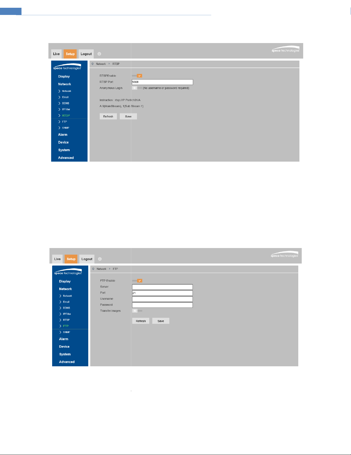
Note that RTSP streaming is used to stream the video to the NVR, so it is highly recommended to leave this
port
that can be used to pla
, there is no need
from events
: The username and password
Check this option to transfer images to the FTP server.
4.3.5 RTSP
Go to Network->RTSP as shown below.
Select “Enable” to enable the RTSP function.
enabled.
Port: Access port of the streaming media. The default
RTSP URL: The RTSP address format
If “Allow anonymous login” is checked
4.3.6 FTP
After an FTP server is set up, captured images
Go to the Network->FTP.
is 9008.
y the stream in a media player.
to enter the username and password to view the video.
will be uploaded to the FTP server.
Server: The IP address or domain name of the FTP.
Port: Port of the FTP server.
User Name and Password
Transfer Images:
that are used to login to the FTP server.
10
Page 15

IP Camera User Manual
To get camera status, parameters and alarm information and remotely manage the camera, the SNMP function
meters of SNMP, such as SNMP port, trap address.
, v3) according to the version of the SNMP software that will be used.
Set the values for “Read SNMP Community”, “Write SNMP Community”, “Trap
can be used
Address”, “Trap Port” and so on. Please make sure the settings
4.3.7 SNMP
install an SNMP management tool and set the para
1. Go to the SNMP section.
2. Select the appropriate version (v1, v2c
3.
are the same as that of the SNMP software.
. Before using SNMP, please
11
Page 16

IP Camera User Manual
Check “Enable” to activate motion based alarms. If
the NVR or the VMS, even if there is motion in the video.
Higher sensitivity value means that motion will be triggered more easily
capture
, click and drag the mouse to define the region as desired in the image
There are 6 different log options available: System, Config, Alarm, User, Network, and All. Choose the log type, the starting
and the end time for log retrieval. Click on Search to retrieve the list of logs.
unchecked, the camera will not send out any signals to trigger motion
email the images to the email address(es) that were set up in
window.
4.4 Motion Setup
4.4.1 Motion Detection
Go to AlarmMotion to set up motion detection.
Sensitivity:
Send Email: If selected, the system will
the Email section.
To set the motion detection area
4.5 Device Log
4.5.1 Log
Go to DeviceLog.
-based recording to
.
images on motion detection and
time,
12
Page 17

IP Camera User Manual
the camera firmware can be updated
” button to select the location of the firmware file.
” button to start upgrading the
Do not close the browser or disconnect the camera from the network during the upgrade
restore the device settings to factory default
reboot the device.
If desired, the camera can be set up to reboot on a time interval.
Reboot” and then set the interval and time.
4.6 Advanced Configuration
4.6.1 Firmware Update
Go to AdvancedFirmware Update. In this interface,
.
1. Click the “Scan
2. Click the “Start
3. The device will restart automatically.
Caution!
4.6.2 Factory Default
Go to AdvancedLoad Default.
Factory Default
Check the relevant options and click Save to
4.6.3 Auto Reboot
Go to AdvancedMaintain.
Click the “Reboot” button to manually
firmware.
.
.
Timed Reboot Setting:
Enabled “Auto
save the settings.
13
Click the “Save” button to
Page 18

IP Camera User Manual
Appendix
Appendix 1 Troubleshooting
IP Scanner does not show any device.
Make sure that the PC that’s running IP Scanner is on the same local network as the devices.
Internet Explorer cannot download ActiveX control.
IE browser may be set up to block ActiveX. Follow the steps below.
1. Open IE browser and then click Tools->Internet Options
2. Select Security and then Custom Level
3. Enable all the options under “ActiveX controls and plug-ins”.
4. Click OK to finish setup.
14
 Loading...