

Page 1

OO22SS11 OOwwnneer
Rev.1.0 (Nov., 2011)
1
ONSIP 02S1
r
’
’
ss MMaannuuaall
Page 2

OO22SS11 OOwwnneer
Rev.1.0 (Nov., 2011)
2
Note
This equipment has been tested and found to comply with the limits for a Class a digital device,
pursuant to part 15 of the FCC Rules. These limits are designed to provide reasonable protection
against harmful interference in a residential installation. This equipment generate, uses and can
radiate radio frequency energy and, if not installed and used in accordance with the instructions, may
cause harmful interference to radio communications. However, there is no guarantee that interference
will not occur in a particular installation. If this equipment does cause harmful interference to radio or
television reception, which can be determined by turning the equipment off and on, the user is
encouraged to try to correct the interference by one or more of the following measures:
Reorient or relocate the receiving antenna.
Increase the separation between the equipment and receiver.
Connect the equipment into and outlet on a circuit different from that to which the receiver is
connected
Consult the dealer or an experienced radio/TV technician for help.
r
’
’
ss MMaannuuaall
Page 3

OO22SS11 OOwwnneer
Rev.1.0 (Nov., 2011)
3
Date
Revision
Details
2011-11-01
1.0
First manual revision creation.
Caution
Any changes or modifications to this device could void the warranty.
Directions
▪ Be careful not to cause any physical damage by dropping or throwing ONSIP O2S1.
▪ Especially keep the device out of reach from children.
▪ Do not disassemble ONSIP O2S1. No After Service is assumed when disassembled.
▪ Use only the power adapter provided with ONSIP O2S1.
▪ Be careful to prevent moisture or water penetration into the unit. Particular attention is
needed when installing ONSIP O2S1. The screw holes for the installation screws and pipe
should be maintained water tight during the whole life time of the product.
▪ All the electrical connection wires running into the unit should be prepared so that water
from the outside cannot flow into the unit through the surface of the wires. Penetration
of the moisture through the wire for extended period can cause malfunction of the unit or
deteriorated image.
r
’
’
ss MMaannuuaall
Revision History
Page 4

OO22SS11 OOwwnneer
Rev.1.0 (Nov., 2011)
4
’
’
ss MMaannuuaall
r
Contents
Contents.......................................................................................... 4
1. Introduction ................................................................................ 5
1.1. Overview ................................................................................................ 5
1.2. Specification ........................................................................................... 6
1.3. Applications of ONSIP O2S1 ................................................................... 7
2. Product Description ..................................................................... 8
2.1. Contents ................................................................................................ 8
2.2. Product Preview...................................................................................... 9
2.3. Physical description .............................................................................. 10
2.4. Functional Description .......................................................................... 12
2.5. Sensor-IN and Relay-OUT ..................................................................... 14
3. Getting Started ......................................................................... 17
3.1. PC Requirement .................................................................................... 17
3.2. Quick Installation Guide ....................................................................... 18
4. Trouble Shooting ....................................................................... 24
4.1. Video movement is slow. ...................................................................... 24
4.2. The image is dull and I see green, pink dots. ........................................ 24
4.3. Mosaic phenomenon. ............................................................................ 24
4.4. Cannot connect to the Video ................................................................. 24
4.5. Windows Vista or Windows 7 ................................................................ 25
4.6. Technical Assistance ............................................................................. 28
Page 5

OO22SS11 OOwwnneer
Rev.1.0 (Nov., 2011)
5
’
’
ss MMaannuuaall
r
1. Introduction
1.1. Overview
The ONSIP O2S1 is a state-of-the-art Megapixel, multi-codec (H.264, MJPEG) Day/Night IP camera built with
embedded software and hardware technology. It enables real time transmission of synchronized video of up to 2
Megapixels and audio data. Remote clients can connect to ONSIP O2S1 for the real time video/audio data
through various client solutions running on PC, Smart Phones (iPhone/Android). Real time 2-way
communication is available through bidirectional audio communication feature.
Designed to be a stand-alone streaming audio & video transmission device, ONSIP O2S1 can be applied to
various application area such as video security, remote video monitoring, distance education, video conference
or internet broadcasting system.
Use the optional integrated backup battery to insure connection continuity when local power is unreliable.
Additional options are, IR illumination, and integrated Pan/Tilt motor.
Based on Speco Technology’s Embedded Software Solution (Embedded Web Server, Embedded Streaming
Server & Network Protocol), the ONSIP O2S1 delivers unprecedented performance and stability. Weather
your application is basic, or scaling to the enterprise, Speco Technology Network Video Recording Applications
(NVR PRO) offer highly reliable methods of managing your security video.
Additional options are:
Integrated Battery backup
(Provides valuable standby power in the event of a power failure)
Integrated IR Illumination for super reliable “Day/Night” Video
Integrated Motorized Pan/Tilt
(Allowing for remote Pan /Tilt camera movement)
Page 6

r
Rev.1.0 (Nov., 2011)
6
Category
Sub-Category
Details
Video
Compression
H.264/MJPEG
Resolution
**Refer to the datasheet.
Audio
(Bi-directional)
Up
32 Kbps G.726
Down
64 Kbps PCM
Network
Interface
100BaseT, IEEE 802.11b/g/n
Access network
Static, DHCP, PPP/PPPoE
Application
RTP, RTSP, SMTP, FTP, HTTP, SDP,
NTP, DNS, HTTPS
I/O
Sensor In 1 NC, NO Selectable
Relay Output
1
For alarm annunciation or
remote ON/OFF control (30V, 1A)
RS-232C
For factory use only
Power Supply
Proprietary Power over Ethernet
Mounting
Wall Mount Bracket
Motion Detection
3 zones
Arbitrary shape with independent sensitivity
Upgrade
Firmware upgrade over IP network
Administration
Remote administration over IP network
Client & Viewer
Web Viewer
Simple viewing over Internet Explorer
Speco-NVR
Standard CMS software
Dynamic IP support
DDNS support
Supported
Security
ID and Password protection
IP filtering for restricting administrative access for audio and bi-audio
Time management
Sync to PC
Synchronize to PC
Manual
Manual time setting
Internet Time Server
Synchronize to Time Server
DLS
Day Light Saving
SDK support
Active-X
HTTP
OO22SS11 OOwwnneer
’
’
ss MMaannuuaall
1.2. Specification
Page 7

OO22SS11 OOwwnneer
Rev.1.0 (Nov., 2011)
7
’
’
ss MMaannuuaall
r
1.3. Applications of ONSIP O2S1
Security surveillance (buildings, stores, manufacturing facilities, parking lots, banks, government facilities,
military, etc.)
Remote monitoring (hospitals, kindergartens, traffic, public areas, etc.)
Teleconference (Bi-directional audio conference).
Real time Internet broadcasting
Distance (Remote) Learning/Education
Page 8
OO22SS11 OOwwnneer
Rev.1.0 (Nov., 2011)
8
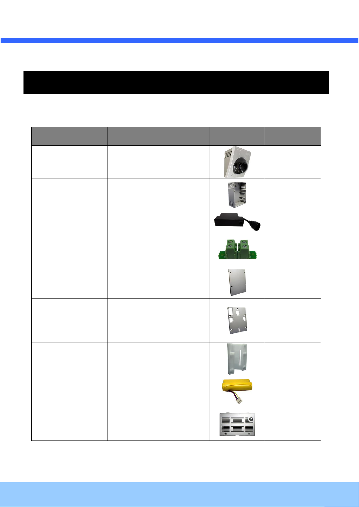
Contents
Description
Shape
Remarks
Main Body
ONSIP O2S1 IP Camera
Adaptor Box
Back Box for housing adaptors
Power Adaptor
Power adaptor with proprietary
PoE.
AC connector PBA
Installed inside the Back box for
connecting AC power to the power
supply.
Adaptor box cover
Back box cover.
Mounting bracket
Mounting bracket for installing the
main body on the wall or
connecting the power adaptor box
with the main body.
Corner Mount Bracket
Corner Mount Adapter
Battery
Li-ion battery pack
Battery cover
Battery compartment cover.
’
’
ss MMaannuuaall
r
2. Product Description
2.1. Contents
The product package contains followings:
Page 9
OO22SS11 OOwwnneer
Rev.1.0 (Nov., 2011)
9
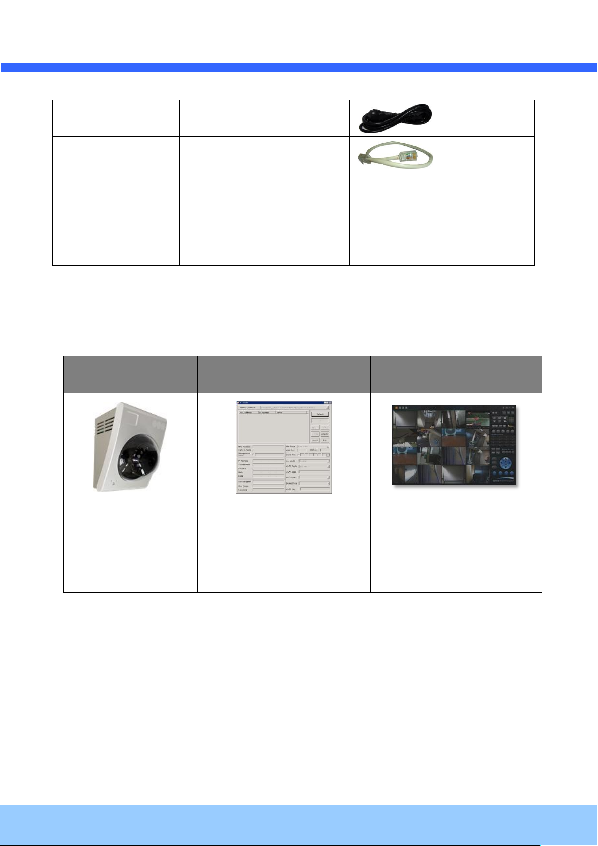
AC cable
AC cable
LAN cable
Short Network LAN cable for
Ethernet and PoE applications
Screws and mounting
fixtures
Screws (33 pieces or 7 types) and
washers (15 pieces of 3 types)
Terminal block
Terminal block for connecting one
sensor input and one relay output.
CD & Documents
Software & User’s Guide
ONSIP O2S1
IP-Installer
CMS Software
(Speco-NVR)
Mega pixel IP Camera
PC software to allocate an IP
address to the IP Camera
PC software to view and record
the A/V streaming data transmitted
from IP camera.
(Simultaneous support of up to 64
IP cameras)
’
’
ss MMaannuuaall
r
2.2. Product Preview
Page 10

OO22SS11 OOwwnneer
Rev.1.0 (Nov., 2011)
10
’
’
ss MMaannuuaall
r
2.3. Physical description
2.3.1. Exterior View
Figure 2-1. Exterior view of ONSIP O2S1
Status LED: Integrated microphone
Status LED: Green color indicates that the camera is in normal operation mode, while RED color
indicates that the camera is in abnormal condition.
MICROPHONE: Integrated microphone
Speaker: Integrated speaker
Page 11

r
Rev.1.0 (Nov., 2011)
11
OO22SS11 OOwwnneer
Factory Default Reset: Used for returning the network camera to the factory default state. One must
open the cover in order to access the switch. To reset: Power down the camera, next while powering up
the camera, hold down the reset switch for three seconds.
2.3.2. Power Adaptor and Accessories
’
’
ss MMaannuuaall
Figure 2-2. PoE power adaptor, accessories and installation
Page 12

OO22SS11 OOwwnneer
Rev.1.0 (Nov., 2011)
12
Pin
Description
Misc.
3
TxD of RS-232C
For debugging & factory use only.
4
RxD of RS-232C
For debugging & factory use only.
5
Ground of RS-232C
For debugging & factory use only.
Pin
Description
Misc.
1
Sensor In (+)
NC/NO selectable in admin mode.
2
Sensor In (-)
NC/NO selectable in admin mode.
3
Relay out
Normal close
4
Relay out
Common
Red/Green LED will be lit with red momentarily and it will be lit with green after a while when
power is applied into ONSIP O2S1
’
’
ss MMaannuuaall
r
2.4. Functional Description
100Base-T
100Mbps Ethernet connector (RJ-45) with proprietary PoE. 2 LEDs on the Ethernet connector shows the
status of ONSIP O2S1 as the followings:
- Status LED (Dual Color): It will be lit in green or red depending on the status.
Green: Green color indicates that the camera is in normal operation mode. Continuous green
indicates that data transmission is possible. Blinking green means that someone is
connected to ONSIP O2S1.
Red: Continuous or blinking red indicates that hardware is in abnormal condition.
- LINK/LAN LED (Orange)
It will be lit with orange color when network cabling is all right. Blinking orange color indicates that
normal data transmission is under way. Off state indicates that there is trouble in network connection.
RS-232C
RS232C interface is provided through mini-USB type connector. The pin assignments are shown in the
following table. RS-232C is reserved for factory usage only.
Sensor In/Relay Out: used for connecting input sensors, and alarm devices to ONSIP O2S1
Sensor Input: Connect external alarm sensors such as the infrared sensors, heat
Page 13

OO22SS11 OOwwnneer
Rev.1.0 (Nov., 2011)
13
sensors, magnetic contacts, etc. (NC/NO selectable on the admin page.)
Relay Output: It is used for connecting external alarm generators such as sirens,
flashing light, etc. When activated, relay output configures a closed circuit.
r
’
’
ss MMaannuuaall
Page 14

OO22SS11 OOwwnneer
Rev.1.0 (Nov., 2011)
14
Figure 2-5. SENSOR input
r
’
’
ss MMaannuuaall
22..55.. SSeennssoorr--IINN aanndd RReellaayy--OOUUTT
Sensor-In and Relay-Out cable is used to connect various sensing and alerting devices. Exam
ples of sensing devices are infrared sensors, motion sensors, heat/smoke sensors, magnetic s
ensor, etc. Relay-Out t is used for connecting alerting device such as loud speaker, flashing li
ght, etc.
1. Sensor-IN
Connect the two wires of the sensors. The sensor type can be set in Administrative
Mode(Ref. 5.6). Output lines providing on-off switching are connected between
“+“ and “-” pins. Figure 6-1 shows the input circuit of “Alarm In”.
Page 15

OO22SS11 OOwwnneer
Rev.1.0 (Nov., 2011)
15
Sensor
Device
Sensor
Power
Supply
NO/NCType
Sensor1-
Sensor1+
+12V
GND
Sensor
Device
Sensor
Power
Supply
Open CollectorType
Photo Coupler
2. Relay-OUT
A Relay output is provided for connecting alarm devices or for remote on/off devices such as light
control. Relay circuits are normal open and circuits are closed upon alarm output or remote on. The
relay is capable of switching AC/DC 30V, 1A electrical signal.
r
’
’
ss MMaannuuaall
3. Connection of Sensor, Alarm Device
3.1 Connection of Sensor
Figure 2-6. RELAY Output
Figure 2-7. Sensor Connection
Page 16

r
Rev.1.0 (Nov., 2011)
16
Alarm
Out
Device
Relay1
Power
Supply(1~30
VDC/AC,1A )
Relay1
+
-
Relay Switch Power Supply
1V~3 0VDC /AC ,1A
Optional
Relay Switch
Alarm
Out
Device
Power
Supply( 30V
~)
Relay
You can use the supported relay output to directly drive a maximum load of 30V
AC/DC at 1A. By connecting additionally relay circuitry (such as optional relay switch),
it can also drive heavier loads.
OO22SS11 OOwwnneer
’
’
ss MMaannuuaall
3.2 Connection of Relay
Figure 2-8. Relay Connection
Page 17

OO22SS11 OOwwnneer
Rev.1.0 (Nov., 2011)
17
Recommended
Remark
CPU
Dual Core 3G above
Main Memory
2GB above
Operating System*
Windows XP
Web Browser
Internet Explorer 6.0 above
Graphic Card
RAM 128MB above
Higher than 1600x1200
Network
100 Base-T Ethernet
’
’
ss MMaannuuaall
r
3. Getting Started
Brief information for first time operation of ONSIP O2S1 is provided in this chapter.
3.1. PC Requirement
Audio/Video streaming data received from ONSIP O2S1 can be displayed or stored in a PC running client
programs. Minimum requirement of the PC is described below:
Page 18

OO22SS11 OOwwnneer
Rev.1.0 (Nov., 2011)
18
’
’
ss MMaannuuaall
r
3.2. Quick Installation Guide
1. Install the battery in the battery compartment and place the battery cover lid.
2. Assemble the power adaptor box as required for your installation condition.
3. Connect ONSIP O2S1 to LAN by using one of the following methods
If you have PoE power adaptor, connect the network camera and PC as illustrated in Figu
re 2.3. both power and network connection are made with a single LAN cable.
Figure 3-1. PoE power adaptor, accessories and installation
Page 19

r
Rev.1.0 (Nov., 2011)
19
Admin Page Button
IP installer
OO22SS11 OOwwnneer
4. Install Speco-NVR
Speco-NVR is a multi-channel CMS program for to IP camera or Video server. Install Speco-NVR on remote PC
to connect to these products. It is needed to assign connection information to Speco-NVR program before
connection.
Insert the CD provided with product into the PC and install the Speco-NVR.
’
’
ss MMaannuuaall
Figure. 3-2. Speco-NVR
Follow the sequence below for setting the IP parameter
i) Run IP installer
ii) Click ① in IP installer window.> Double click on ② > Fill in ④ > make a selection in ⑤ > Fill the
parameters in ⑥
iii) Click on ⑨ to apply the settings.
iv) You can connect to admin page by clicking on ⑩.
Page 20

OO22SS11 OOwwnneer
Rev.1.0 (Nov., 2011)
20
Click on the field in ③ for sorting and rearranging the list.
Select network mode that best suits from the drop down list in ⑤. You can choose either
Static or ADSL and Auto (DHCP), respectively. If ADSL and Auto are selected, the fields in ⑥
is deactivated.
In case of ADSL, fill the User Name and Password in ⑧ with the values provided by your ISP.
i) If DDNS service is needed, Check at the box and fill the empty field with hostname
you want in ⑦.
1 2 3 6 4
9 5 7
8
10
r
’
’
ss MMaannuuaall
Page 21

r
Rev.1.0 (Nov., 2011)
21
Note: Active-X module should be installed on your PC before actual connection. If your PC is
not connected to the internet, you cannot download Active-X module. Most convenient way of
installing the Active-X module is installing Speco-NVR which is available from the CD or our
web site.
Connection to Admin Page
Basic Control Buttons
Video Crop Control
[e.g.] Port 8080
[e.g.] Port 80
Can be omitted the
default port of 80
’
’
ss MMaannuuaall
OO22SS11 OOwwnneer
5. Remote video connection to ONSIP O2S1
1) Connection through Web Viewer
Web Viewer offers simplest way of video connection to ONSIP O2S1. For video connection, enter the
IP address of ONSIP O2S1 in the URL window of Internet Explorer as:
Figure 3-3. Web Viewer
Default ID and password of Admin Page are root, admin. For more detailed information, please refer to the
[Configuration_Guide] Guide.
Page 22

r
Rev.1.0 (Nov., 2011)
22
Camera Assignment
Camera Assignment
Live view
Save
Example
Exit Program
Default ID/PW: admin/1234
OO22SS11 OOwwnneer
2) Connection through Speco-NVR
Speco-NVR is a multi-channel CMS program for to IP camera or Video server. Install Speco-NVR on
remote PC to connect to these products. It is needed to assign connection information to Speco-NVR
program before connection. Details for the Speco-NVR can be found in [Speco-NVR User’s Guide].
’
’
ss MMaannuuaall
Figure 3-4. Speco-NVR
Page 23

r
Rev.1.0 (Nov., 2011)
23
OO22SS11 OOwwnneer
6. Additional settings through connection to the Admin Page
All the parameters of new IP camera follows factory default values. For more sophisticated target application it
is needed to change parameters. The admin page can be connected through
”http://IP_address:HTTP_port_number”/admin.htm
It is needed to enter ID and password of the administrator. Default ID and password are root, admin. It is highly
recommended to change the ID and password to prevent illegal access to the IP camera. For more detailed
information, please refer to the [Configuration_Guide] Guide.
’
’
ss MMaannuuaall
Page 24

OO22SS11 OOwwnneer
Rev.1.0 (Nov., 2011)
24
’
’
ss MMaannuuaall
r
4. Trouble Shooting
44..11.. VViiddeeoo mmoovveemmeenntt iiss ssllooww..
In Basic Setup of Admin Mode, lower the “Quality”. High quality means more data. You can also set the
“Max. Bandwidth” to higher value. But this value must be lower than the maximum upload speed of your
network. For example, if the maximum uploading bandwidth of the network is 400Kbps, set the total “Max.
upload rate” as 384Kbps. If you set it higher, the video image can be corrupted with artifacts.
Ask your network manager or ISP for maximum uploading bandwidth of the network.
44..22.. TThhee iimmaaggee iiss dduullll aanndd II sseeee ggrreeeenn,, ppiinnkk ddoottss..
This could be caused by performance limitation of the PC. Do not run too many programs while running
viewer program. The other reason could be missing data while transmission from ONSIP O2S1
44..33.. MMoossaaiicc pphheennoommeennoonn..
Mosaic phenomenon occurs when not enough network bandwidth is available considering the resolution
and frame rate of the video.
Example is 1280X720 video with low Max. Bandwidth.
Users are recommended to adjust resolution and frame rates to lower values for lower bandwidth network.
4.4. Cannot connect to the Video
Check the status of the network connection through PING test.
Try the following on your PC:
- Start > Run > Cmd > Ping IP address (Ex : Ping 172.16.42.51)
- If “Reply from ~” message is returned ( in the figure below), the network connection is in normal
state. Try connection to the video again. If the problem persists, or refer to other trouble shooting notes.
- If “Request timed out” message is returned ( in the figure below), the network connection or
network setting is not in normal state. Check the network cable and settings.
Page 25

OO22SS11 OOwwnneer
Rev.1.0 (Nov., 2011)
25
1
2
r
’
’
ss MMaannuuaall
4.5. Windows Vista or Windows 7
Windows Vista and Windows 7 users need to configure UAC (User Access Control) and Privilege Level for
proper recording and still video capture in Speco-NVR and Web Viewer.
<Windows Vista>
1. UAC (User Access Control) configuration
1) Double-click “User Accounts” in control panel
2) Double-click “Turn User Account Control on or off”
3) Uncheck “Use UAC to help protect your computer”
Page 26

r
Rev.1.0 (Nov., 2011)
26
OO22SS11 OOwwnneer
2. Privilege Level Control
’
’
ss MMaannuuaall
1) Select “NVR” icon on the desktop
2) Click right mouse button and select “Properties”
3) Check “Privilege Level” in “Compatibility” tab
<Windows 7>
1. UAC (User Access Control) configuration
1) Double-click “User Accounts” in control panel
2) Double-click “Change User Account Control setting”
3) Set to “Never notify”
Page 27

OO22SS11 OOwwnneer
Rev.1.0 (Nov., 2011)
27
r
’
’
ss MMaannuuaall
2. Privilege Level Control
1) Select “NVR” icon on the desktop
2) Click right mouse button and select “properties”
3) Check “Privilege Level” in “Compatibility” tab
Page 28

OO22SS11 OOwwnneer
Rev.1.0 (Nov., 2011)
28
1. Model name
2. MAC address and Registration number
3. Purchase date
4. Description of the problem
5. Error message
’
’
ss MMaannuuaall
r
4.6. Technical Assistance
If you need any technical assistance, please contact your dealer. For immediate service please provide the
following information.
 Loading...