

Page 1

Full HD
30x Speed Dome
IP Camera
ㅋ
O2P30X
Page 2

OO22PP3300XX UUsseerr’’ss GGuuiiddee
2
Directions
Be careful not to cause any physical damage by dropping or throwing the camera. Especially keep t
he device out of reach from children.
Do not disassemble the camera. No after service is assumed when disassembled.
Use only power adapters compatible with the unit.
Be careful to prevent moisture or water penetration into the unit. Particular attention is needed when
installing the unit. The screw holes for the installation screws and pipe should be maintained water
tight during the whole life time of the product.
All the electrical connection wires running into the unit should be prepared so that water from the o
utside cannot flow into the unit through the surface of the wires. Penetration of the moisture through
the wire for extended period can cause malfunction of the unit or deteriorated image.
Note
This equipment has been tested and found to comply with the limits for a Class A digital device,
pursuant to part 15 of the FCC Rules. These limits are designed to provide reasonable protection
against harmful interference in a residential installation. This equipment generate, uses and can
radiate radio frequency energy and, if not installed and used in accordance with the instructions, may
cause harmful interference to radio communications. However, there is no guarantee that interference
will not occur in a particular installation. If this equipment does cause harmful interference to radio or
television reception, which can be determined by turning the equipment off and on, the user is
encouraged to try to correct the interference by one or more of the following measures:
Reorient or relocate the receiving antenna.
Increase the separation between the equipment and receiver.
Connect the equipment into and outlet on a circuit different from that to which the receiver is
connected
Consult the dealer or an experienced radio/TV technician for help.
Caution
Any changes or modifications in construction of this device which are not explicitly approved by the
party responsible for compliance could void the user’s warranty.
Rev.1.3 (Apr. 2016)
Page 3

OO22PP3300XX UUsseerr’’ss GGuuiiddee
3
Revision History
Date Revision Details
Apr 26th, 2016 1.3 First manual revision creation.
Rev.1.3 (Apr. 2016)
Page 4

OO22PP3300XX UUsseerr’’ss GGuuiiddee
4
Contents
1. Introduction ................................................................................................................................................... 5
1.1. Overview ............................................................................................................................................... 6
1.2. Specifications ........................................................................................................................................ 7
2. Product Description ...................................................................................................................................... 9
2.1. Contents ................................................................................................................................................ 9
2.2. Product Preview .................................................................................................................................. 10
2.3. Physical description ............................................................................................................................ 11
2.3.1. Parts Name & Functions ........................................................................................................... 11
2.3.2. External Connector ................................................................................................................... 12
2.4. Functional Description ........................................................................................................................ 13
3. On Site Installation ...................................................................................................................................... 15
4. Getting Started ............................................................................................................................................ 17
4.1. PC Requirement ................................................................................................................................. 17
4.2. Quick Installation Guide ...................................................................................................................... 18
4.2.1. Connect PC and O2P30X to network. ...................................................................................... 18
4.2.2. Set IP parameters on O2P30X .................................................................................................. 18
4.2.3. Remote video connection to O2P30X ...................................................................................... 19
4.2.4. Additional settings through connection to the Admin Page ...................................................... 21
5. Troubleshooting .......................................................................................................................................... 22
5.1. No power is applied ............................................................................................................................ 22
5.2. Cannot connect to the Video............................................................................................................... 22
5.3. Technical Assistance ........................................................................................................................... 23
6. Starting OSD Menu ...................................................................................................................................... 24
6.1. Preset .................................................................................................................................................. 24
6.2. Auto scan ............................................................................................................................................ 24
6.3. Pattern ................................................................................................................................................ 25
6.4. Tour ..................................................................................................................................................... 25
6.5. Other Functions .................................................................................................................................. 26
6.6. OSD Menu .......................................................................................................................................... 27
6.7. Using the Menu ................................................................................................................................... 27
Rev.1.3 (Apr. 2016)
Page 5

OO22PP3300XX UUsseerr’’ss GGuuiiddee
5
6.8. Main Menu .......................................................................................................................................... 28
6.9. Dome Setup ........................................................................................................................................ 28
6.10. OSD Display ....................................................................................................................................... 29
6.11. System Status ..................................................................................................................................... 29
6.12. Initialize ............................................................................................................................................... 29
6.13. Camera Setup ..................................................................................................................................... 30
6.14. Focus Setup ........................................................................................................................................ 31
6.15. Image Adjust ....................................................................................................................................... 31
6.16. White Balance Setup .......................................................................................................................... 31
6.17. Auto Exposure Setup .......................................................................................................................... 32
6.18. AE Mode Setup ................................................................................................................................... 33
6.19. Preset Set ........................................................................................................................................... 34
6.20. Edit Scene - Preset ............................................................................................................................. 34
6.21. Edit Label - Preset .............................................................................................................................. 35
6.22. Auto Scan Set ..................................................................................................................................... 36
6.23. Tour Set ............................................................................................................................................... 37
6.24. Edit Tour .............................................................................................................................................. 37
6.25. Privacy Set .......................................................................................................................................... 39
6.29. Sector Set ........................................................................................................................................... 41
6.30. Edit Scene - Setor ............................................................................................................................... 41
6.31. Edit Label - Sector .............................................................................................................................. 42
6.32. Edit Sector Label ................................................................................................................................. 43
6.33. Default Settings ................................................................................................................................... 43
1. Introduction
Rev.1.3 (Apr. 2016)
Page 6

OO22PP3300XX UUsseerr’’ss GGuuiiddee
6
1.1. Overview
The ONSIP O2P30X is multi-codec (H.264, MJPEG) IP camera (or network camera) built with embedded
software and hardware technology. It enables real time transmission of synchronized video of up to 1,080P and
audio data. Remote clients can connect to IP Camera for the real time video/audio data through various client
solutions running on PC or smart device. Real time 2-way communication is available through bidirectional
audio communication feature.
Designed to be a stand-alone streaming audio & video transmission device, ONSIP O2P30X can be applied to
various application area such as video security, remote video monitoring, distance education, video conference
or internet broadcasting system.
Embedded PoE+ (Power over Ethernet, IEEE 802.3at) will enable the owner to reduce TCO (Total Cost of
Ownership) by reducing on-site wiring works for the installation.
Rev.1.3 (Apr. 2016)
Page 7

OO22PP3300XX UUsseerr’’ss GGuuiiddee
7
1.2. Specifications
Camera
Image Sensor 1/3" Panasonic CMOS image sensor
Sync. System Internal
Effective Pixels Number 1920 (H) x 1080 (V) 2.0 Mega
Horizontal Resolution 1100 TV Lines
Video Output Level
Lens
Min. Illumination
Day & Night System Auto/ Day/Night
Focus Auto/ Manual/ Semi-Auto
Iris Auto/ Manual(CLOSE,F1.6 ~ F14)
Shutter Speed Auto/ Manual(1/1 sec ~ 1/10,000 sec)
AGC Auto/ Manual (-3dB ~ +28dB)
White Balance Auto/ One Push/ ATW/ Manual( Red, Blue Gain Adjustable)
PAN/TILT
Operation Angle Pan 360°(Endless)/ Tilt 190° (Auto-Flip ON), 100° (Auto-Flip OFF)
Operation Speed
Presets
Digital Output (YCbCr 4:2:2) / LVDS, HD Analog Component,
Select NTSC/PAL 1.0Vp-p (75Ω, composite)
960x Zoom (30x Optical, 32x Digital), 4.3(W)mm~129(T)mm,
F1.6(W)~F5.0(T)
Color : 0.5 lux , BW : 0.1lux
Dss Color : 0.002 lux , BW : 0.001 lux
Preset 540°/sec
Manual 1° ~ 240°/sec (Linked with zooming)
Swing 1° ~ 180°/sec
254 Presets(Labeled, individual video setup,
※
“ 95 preset: enter menu)
Patterns 8 Pattern ,1200 Commands (about 5 minutes)/Pattern
Swings 8 swings
Groups 8 groups(20 operations/group)
Other Functions AUTO FLIP, POWER UP ACTION, etc
Network
Video Compression H.264 / MJPEG
Multi-Video Streaming Max. 5 (2MP, D1, CIF, Crop, Photo)
Streaming Method
RTSP Streaming with Proprietary Format for Control Information
- Standard RTSP Streaming
- HTTP Streaming
Rev.1.3 (Apr. 2016)
Page 8

OO22PP3300XX UUsseerr’’ss GGuuiiddee
8
Bit Rate Control Intelligent Hybrid Control (VBR+CBR)
Max. Frame Rate 30fps@2MP
External Terminals
2 Way-Audio
Network Protocols
Security User ID & Password Protection, IP Filtering, HTTPS, SSL
LAN 10/100 Base T LAN (Auto MDIX)
GENERAL
Alarm I/O 1 input, 1 output
Privacy Zone 8 Zones
OSD menu ON /OFF/ AUTO
Input Voltage AC 24V/2A(MAX. 48VA), PoE+ (IEEE802.3at)
Dimension
Weight
32Kbps G.726 ADPCM, 64Kbps 16bit µ-law PCM ~ MIC / Line-in
64Kbps 16bit µ-law PCM ~ Line-out
IPv4/v6, TCP, UDP, IGMP, ICMP, ICMPv6, ARP, RARP, PPPoE,
RTCP, RTP, RTSP, SDP, HTTP, HTTPS, SMTP, FTP, DHCP,
UPnP, SNMP, NTP, DNS, DynDNS, SOCKS, ONVIF
Dome: ∅156.3
Housing: ∅ 189.0 x 265.7(H) mm (without Sun-Shield)
3.8kg (without Sun-Shield) / 4.3kg (with Sun-Shield)
Rev.1.3 (Apr. 2016)
Page 9
OO22PP3300XX UUsseerr’’ss GGuuiiddee
9
2. Product Description
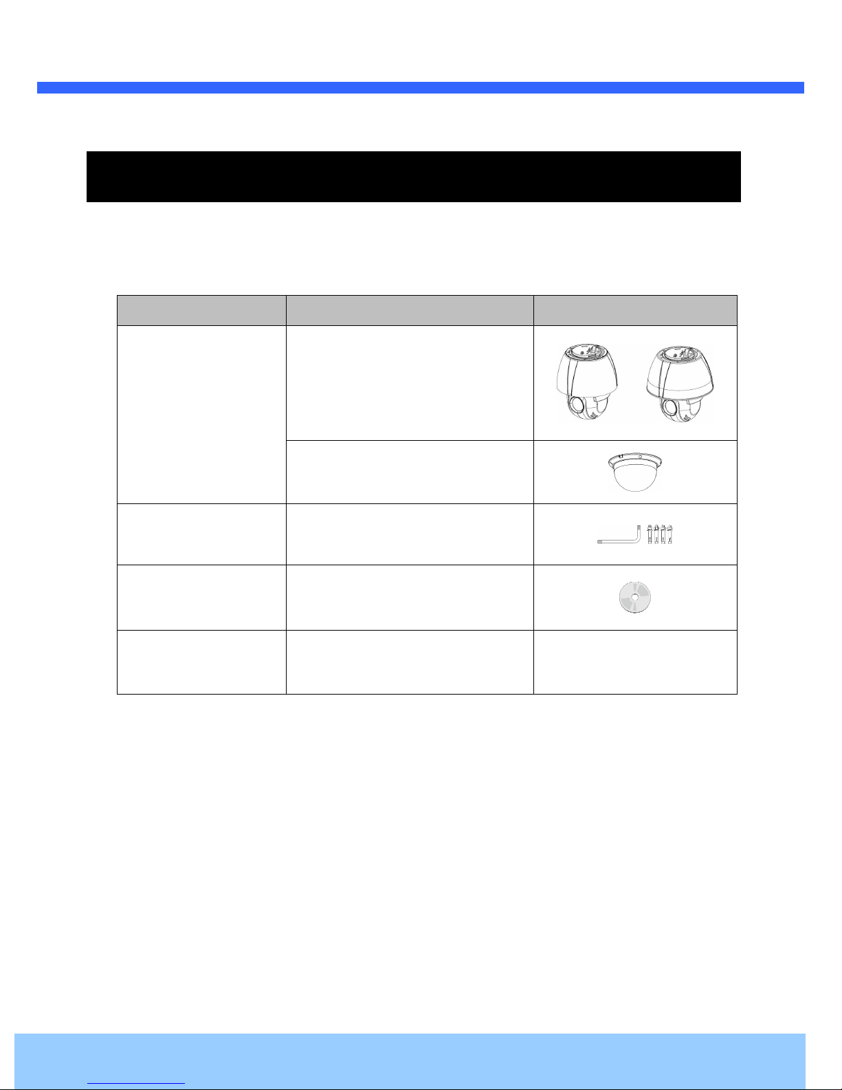
2.1. Contents
The product package contains followings :
Contents Description Remarks
O2P30X main unit
O2P30X
O2P30X Dome Cover
Accessories
CD
Power Adaptor
L-type wrench, Anchor Bolt
Software & User’s Guide
Default built in standard PoE module
(IEEE802.3af)
24V AC Adaptor
(Optional item)
Rev.1.3 (Apr. 2016)
Page 10
OO22PP3300XX UUsseerr’’ss GGuuiiddee
10
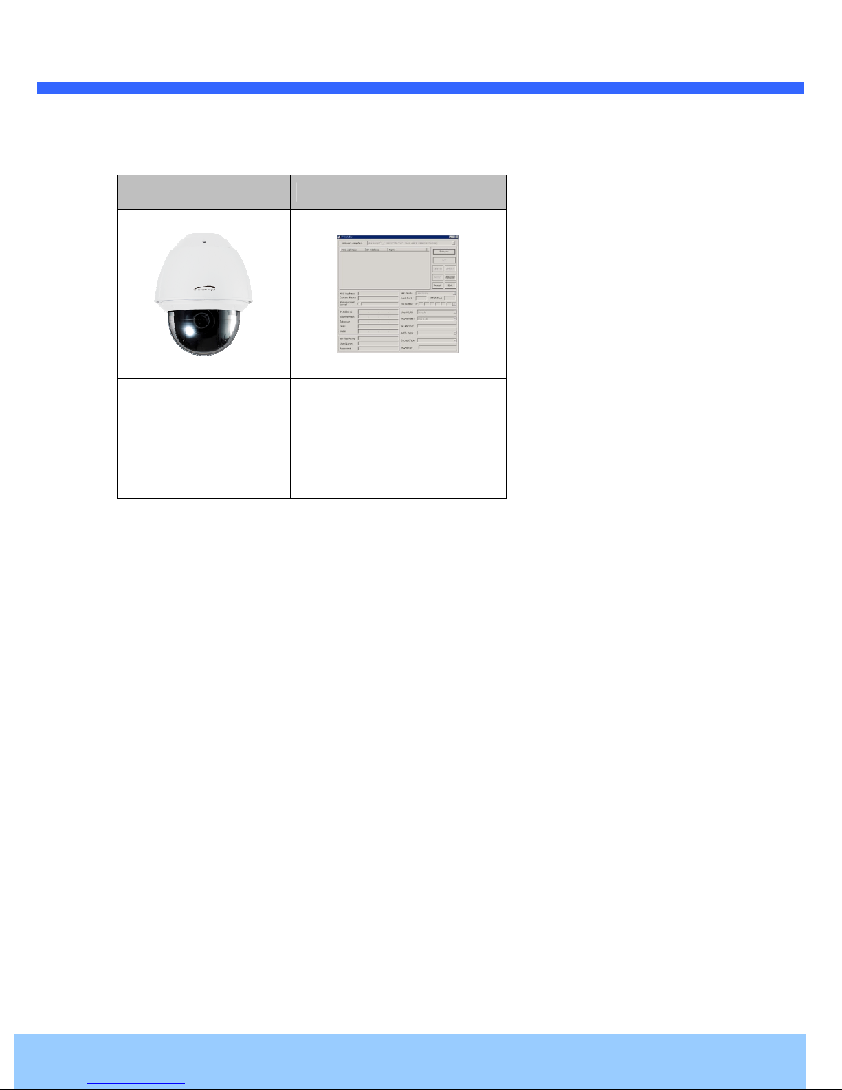
2.2. Product Preview
O2P30X ONSIP Installer
Speed Dome
IP Camera
PC software to allocate an IP
address to the IP Camera
Rev.1.3 (Apr. 2016)
Page 11
OO22PP3300XX UUsseerr’’ss GGuuiiddee
11
2.3. Physical description
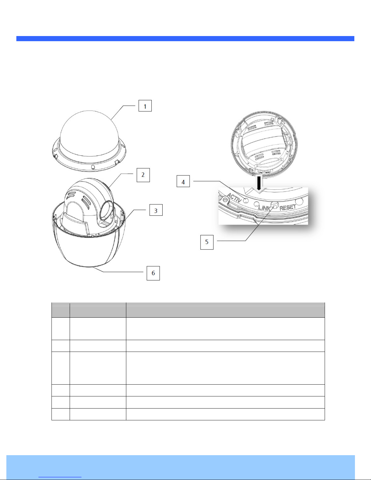
2.3.1. Parts Name & Functions
Figure 2-1. Parts Name & Functions
Part Function Description
Dome Cover
1
DIP Switch
2
Drop Prevention
Spring
3
LED
4
Reset Switch
5
DIP Switch
6
Do not detach protection vinyl from dome cover before finishing all
installation process to protect dome cover from scratches or dust.
Set up camera ID and protocol.
This part keeps the camera from dropping during installation and
maintenance. After install the Bracket, please, hang the spring to the drop
prevention hook of main body as shown in picture for further tasks.
ACTIVE/LINK Network operation and connected status can be checked.
Network Board Factory reset
Set up RS485 Termination
Rev.1.3 (Apr. 2016)
Page 12
OO22PP3300XX UUsseerr’’ss GGuuiiddee
12
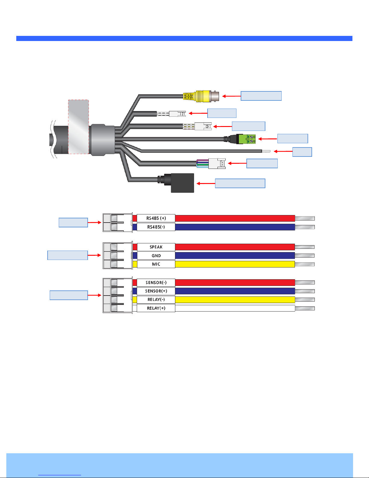
2.3.2. External Connector
Video output
RS485
Audio I/O
AC 24V
GND
Sensor I/O
Network (LAN)
RS485
Audio I/O
Sensor I/O
Figure 2-4. Connector for external connection
Rev.1.3 (Apr. 2016)
Page 13
OO22PP3300XX UUsseerr’’ss GGuuiiddee
13
2.4. Functional Description
Power : Power input for supplying AC 24V power.
Rated Power Input Voltage Range Current Consumption
AC 24V
PoE+ (IEEE802.3at)
Do uses more than CAT5 Cable.
Caution : If IP Camera is powered by PoE+, do not plug in AC Jack with active AC
power into AC power connector.
Network (LAN)
10Mbps or 100Mbps Ethernet connector (RJ-45) with PoE+ standard (IEEE802.3at).
Video Connection
Connect with the supplied Cable. (For installation).
Audio Input/Output Connection
Connect with audio input/output device.
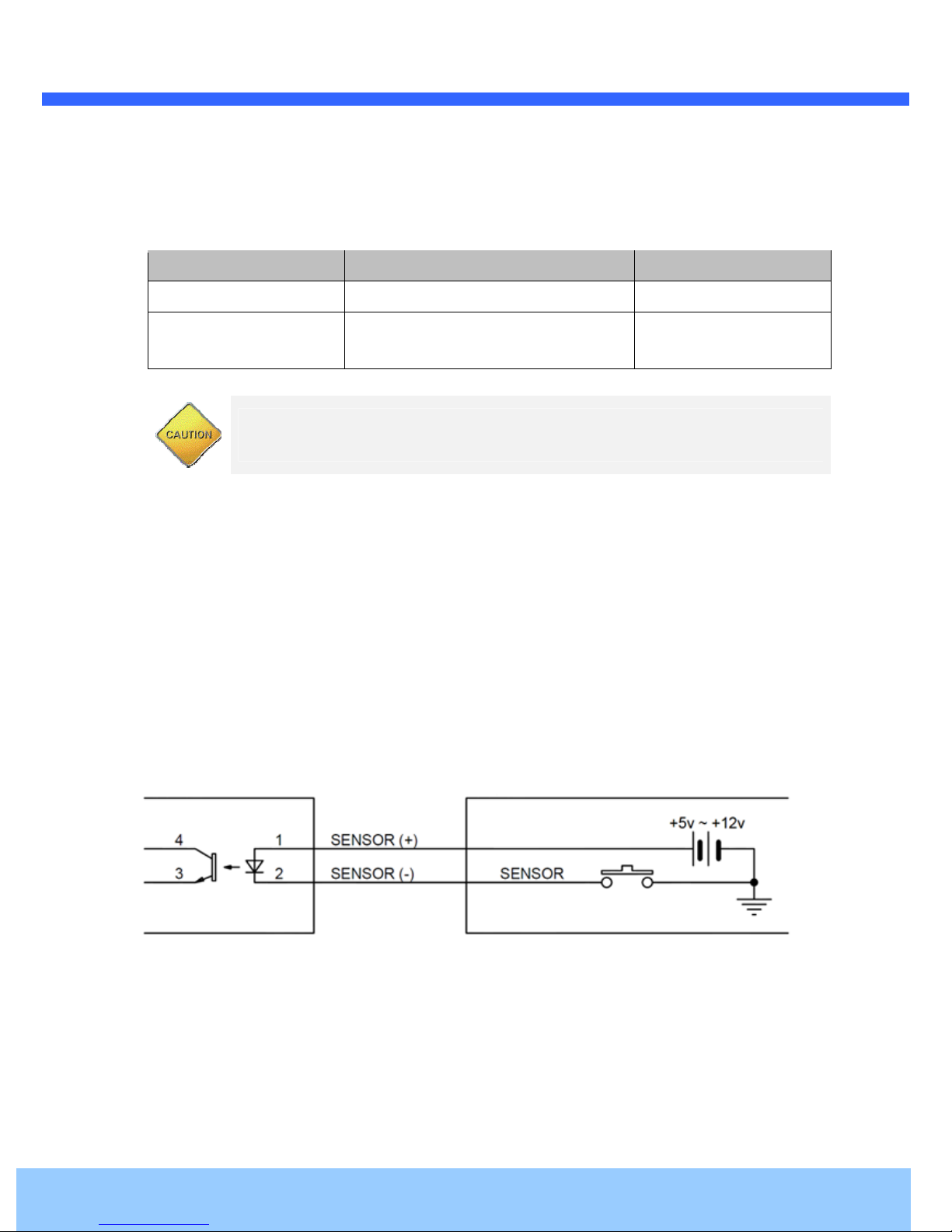
Sensor Input
Internal
AC24V ± 10% 2A
DC 36V~57V
External
MAX 24W
Figure 2-5. SENSOR Input connection
Before connecting sensors, check driving voltage and output signal type of the sensor. Since output
signal types of the sensors are divided into Open Collector and Voltage Output type in general, the
cabling must be done properly after consideration.
Rev.1.3 (Apr. 2016)
Page 14

OO22PP3300XX UUsseerr’’ss GGuuiiddee
14
Signal Description
SENSOR(+)
SENSOR(-)
If you want to use Alarm Input, the types of sensor must be selected in OSD menu. The sensor types are
Normal Open and Normal Close. If sensor type is not selected properly, the alarm can be activated
reversely.
Signal Description
Normal Open
Normal Close
Relay Output
Connect (+) cable of electric power sources for Sensors to this port as shown in the
circuit above.
Connect output of sensors for each port as shown in the circuit above.
Output Voltage is high state when sensor is activated.
Output Voltage is high state when sensor is not activated.
Maximum allowable electrical load of relay is shown below table.
Driving Power DC AC
Max. Load
Figure 2-6. RELAY Output connection
DC 24V / 1A AC 125V / 0.5A
Rev.1.3 (Apr. 2016)
Page 15

OO22PP3300XX UUsseerr’’ss GGuuiiddee
15
3. On Site Installation
3.1. Installation Using the Wall Mount
When installing the bracket to main body,
match the main( | ) and bracket( | ).
Main Body turn to the right to match the
main body( | ) and bracket( || ).
Rev.1.3 (Apr. 2016)
Page 16

OO22PP3300XX UUsseerr’’ss GGuuiiddee
16
3.2. Installation Using the Pendant Mount
Accessories supplied as CABLE ASSY, PIPE,
PENDANT MOUNT and assemble as shown.
Rev.1.3 (Apr. 2016)
Page 17

OO22PP3300XX UUsseerr’’ss GGuuiiddee
17
4. Getting Started
Brief information for first time operation of O2P30X is provided in this chapter.
4.1. PC Requirement
Audio/Video streaming data received from IP Camera can be displayed or stored in a PC running client
programs. Minimum requirement of the PC is described below:
Item Minimum Requirements Recommended Specifications
CPU Intel Core i3 3Ghz Intel Core i7
Main Memory 2GB 4GB
Operating System* Windows 7 Windows 7 (64bit)
Web Browser Internet Explorer 8 or higer Internet Explorer 8 or higher
Graphic Card
Video RAM 256MB
Resolution 1920x1080
Network 10 Base-T Ethernet 100 Base-T Ethernet
* Operating Systems supported: Windows 2000 Professional, Windows XP / Vista / 7
Video RAM 1GB
Higher than 1920x1080
Rev.1.3 (Apr. 2016)
Page 18

OO22PP3300XX UUsseerr’’ss GGuuiiddee
18
LAN switch with
standard POE+
LAN switch
AC adaptor
4.2. Quick Installation Guide
4.2.1. Connect PC and O2P30X to network.
1. Prepare a PC to run programs for the installation and video connection
(PC is needed to assign IP address to OP230X)
2. In the case of using PoE, connect the PC and O2P30X to the network using one of the following ways.
If your LAN Switch does not support standard PoE, connect O2P30X as shown in dotted line in Figure.
The DC power is applied through DC adapter.
Figure 4-1 Power and network connection
4.2.2. Set IP parameters on O2P30X
Follow the sequence below for setting the IP parameter
i) Run ONSIP installer
ii) Click (1) in ONSIP installer window.> Double click on (2) > Fill in (4) > make a selection in (5) > Fill the
parameters in (6)
iii) Click on (9) to apply the settings.
iv) You can connect to admin page by clicking on (10).
Rev.1.3 (Apr. 2016)
Page 19

OO22PP3300XX UUsseerr’’ss GGuuiiddee
19
1
2
3
6
4
9
5
7
8
10
Click on the field in (3) for sorting and rearranging the list.
Select network mode that best suits from the drop down list in (5). You can choose either Static or
ADSL and Auto (DHCP), respectively. If ADSL and Auto are selected, the fields in (6) are
deactivated.
In case of ADSL, fill the User Name and Password in (8) with the values provided by your ISP.
If DDNS service is needed, Check at the box and fill the empty field with hostname you want in
(7).
4.2.3. Remote video connection to O2P30X
1. Connection through Web Viewer
Web Viewer offers simplest way of video connection to O2P30X. For video connection, enter the IP
address of O2P30X in the URL window of Internet Explorer as:
[e.g.] Port 80
Default port 80 can be omitted
Rev.1.3 (Apr. 2016)
Page 20

OO22PP3300XX UUsseerr’’ss GGuuiiddee
20
[e.g.] Port 8080
Note : Active-X module should be installed on your PC before actual connection. If your PC is
not connected to the internet, you cannot download Active-X module. Most convenient way of
installing the Active-X module is installing Speco-NVR which is available from the CD or our
web site.
Connection to Admin Page
Basic Control
Default ID and password of Admin Page are “admin”, “1234”.
For more detailed information, please refer to the “Configuration Guide”.
Figure 4-3. Web Viewer
Rev.1.3 (Apr. 2016)
Page 21

OO22PP3300XX UUsseerr’’ss GGuuiiddee
21
4.2.4. Additional settings through connection to the Admin Page
All the parameters of new IP camera follows factory default values. For more sophisticated target
application it is needed to change parameters. The admin page can be connected through
“http://IP_Address:Port_Number/admin.htm”
ID and password of the administrator are required. Default ID and password are “admin”, “1234”.
It is highly recommended to change the ID and password to prevent illegal access to the IP camera.
For more detailed information, Please refer to the “Configuration Guide”.
Rev.1.3 (Apr. 2016)
Page 22

OO22PP3300XX UUsseerr’’ss GGuuiiddee
22
2
5. Troubleshooting
5.1. No power is applied
In case of Standard PoE+ (Power over Ethernet)
Power supply through standard PoE+ is possible only when the following conditions are met.
1. Standard PoE+ is supported on the product.
2. The LAN switch supports standard PoE+.
Make sure that both the IP camera and the LAN switch support standard PoE+ (IEEE 802.3at)
In case of AC adaptor
If PoE+ is not applied, the power and network connection should be made through separate cables.
It is recommended to use AC adaptor supplied by provider for the feeding of the power. In case of
replacing the AC power supply, make sure that the power supply meets with the power requirement
of the IP camera to prevent damage or malfunction.
5.2. Cannot connect to the Video
Check the status of the network connection through PING test.
Try the following on your PC :
- Start > Run > Cmd > Ping IP address (Ex : Ping 172.16.42.51)
- If “Reply from ~” message is returned (
state. Try connection to the video again. If the problem persists, or refer to other trouble shooting notes.
- If “Request timed out” message is returned. (
setting is not in normal state. Check the network cable and settings.
1
①①①①
in the figure below), the network connection is in normal
②②②②
in the figure below), the network connection or network
Rev.1.3 (Apr. 2016)
Page 23

OO22PP3300XX UUsseerr’’ss GGuuiiddee
23
5.3. Technical Assistance
If you need any technical assistance, please contact technical support. For immediate service please
provide the following information.
1.
1.
Model name
1.1.
2.
2.
MAC address and Registration number
2.2.
3.
3.
Purchase date
3.3.
4.
4.
Description of the problem
4.4.
5.
5.
Error message
5.5.
Rev.1.3 (Apr. 2016)
Page 24

OO22PP3300XX UUsseerr’’ss GGuuiiddee
24
6. Starting OSD Menu
Function : Using the OSD menu, Preset, Pattern, Auto scan, Tour and Alarm Input function can be
configured for each application.
Enter MENU : “Menu On” Key.
Exit MENU : “Menu Off” Key.
Control Key : Use NEAR(F-) to save values and use FAR(F+) to cancel values.
6.1. Preset
Max. 254 positions can be stored as Preset position. The Preset number can be assigned from 1 to 255, but 95
is reserved. Camera characteristics (i.e. White Balance, Auto Exposure) can be set up independently for each
preset. Label should be blank and “Camera Adjust” should be set to “GLOBAL” as default. All characteristics
can be set up in OSD menu.
Set Preset
Run Preset
Delete Preset
Set Preset [1~255]
Go Preset [1~255]
Del Preset [1~255]
6.2. Auto scan
By using Auto scan function, you can make
camera to move between 2 Preset positions
repeatedly. When auto scan function runs, camera
moves from the preset assigned as the 1st point
to the preset assigned as the 2nd point in CW
(Clockwise) direction. Then camera moves from
the preset assigned as the 2nd point to the preset
assigned as the 1st point in CCW (Counterclock
wise) direction.
In case that the preset assigned as the 1st point is
same as the preset assigned as the 2nd point, camera turns on its axis by 360 ° in CW(Counter wise) direction.
Speed can be set up from 1°/sec to 180°/sec.
Set Auto scan
Run Auto scan
Delete Auto scan
To set Auto scan, use OSD menu.
Run Auto scan [1~8]
To delete Auto scan, use OSD menu.
Rev.1.3 (Apr. 2016)
Page 25

OO22PP3300XX UUsseerr’’ss GGuuiiddee
25
6.3. Pattern
Pattern Function is that a camera memorizes the path(mostly curve path) by screen jog for assigned time and
revives the path exactly as it memorized. 8 Patterns are available and Maximum 1200 communication
commands can be stored in a pattern.
Pattern can be created by one of following two methods.
Method 1) Set Pattern [Pattern NO.]
- Pattern editing screen is displayed as bellow.
- Movement by direction key and preset movement
can be memorized in a pattern.
- The rest memory size is displayed in progress bar.
- To save the recording, press NEAR(F-) and to
cancel, press FAR(F+).
Setting Pattern
EDIT PATTERN1
█ █ █ █ █ █ █ █ █ █ █ █ █ █ █ █ █ █
┌ ┐
└ ┘
[NEAR:SAVE /FAR:DELETE]
0/0/x1/N
Method 2) OSD using OSD menu: See the section “How to use OSD menu”
Run Pattern
Delete Pattern
Run Pattern [1~8]
To delete Pattern, use OSD menu.
6.4. Tour
The tour function allows running sequence of Presets, Pattern and Auto scans. Max 8 tour can be stored. Each
tour can have max 20 action entities which can be preset, pattern or auto scan. Preset speed can be set up and
the repeat number of Pattern & Auto scan can be set up in Tour setup.
Dwell time between actions can be set up also.
Setting Tour
Run Tour
Use OSD Menu to create a Tour.
Run Tour [1~8]
Delete Tour
To delete Tour, use OSD menu.
Rev.1.3 (Apr. 2016)
Page 26

OO22PP3300XX UUsseerr’’ss GGuuiiddee
26
6.5. Other Functions
POWER UP ACTION
AUTO FLIP
CAM ADJUST
(GLOBAL/ LOCAL)
This function enables to resume the last action executed before power down.
Most of actions such as Preset, Pattern, Auto scan and Tour are available for this
function but Jog actions are not available to resume.
In case that tilt angle arrives at the top of tilt orbit (90°), zoom module camera keep
moving to opposite tilt direction (190°) to keep tracing targets. As soon as zoom
module camera passes through the top of tilt direction(90°), images should be
reversed automatically and F appears in screen. If this function is set to OFF, tilt
movement range is -5°~95°.
White Balance and Auto Exposure can be set up independently for each preset.
There are 2 modes, "Global" mode & "Local" mode.
The Global mode means that White Balance or Auto Exposure can be set up totally
and simultaneously for all presets in "ZOOM CAMERA SETUP" menu.
The Local mode means that White Balance or Auto Exposure can be set up
independently or separately for each preset in each preset setup menu.
Each Local White Balance / Auto Exposure value should activate correspondingly
when camera arrives at each preset location. During jog operation, Global White
Balance / Auto Exposure value should be applied. All Local White Balance / Auto
Exposure value do not change although Global White Balance / Auto Exposure
value changes.
FOCUS MODE
(SEMIAUTO)
This mode exchanges focus mode automatically between Manual Focus mode and
Auto Focus mode by operation. Manual Focus mode activates in preset operation
and Auto Focus mode activates during jog operation. With Manual mode at presets,
Focus data is memorized in each preset in advance and camera calls focus data in
correspondence with presets as soon as camera arrives at a preset. It should
shorten time to get focuses Focus mode changes to Auto Focus mode automatically
when jog operation starts.
Rev.1.3 (Apr. 2016)
Page 27

OO22PP3300XX UUsseerr’’ss GGuuiiddee
27
←
←
←
-
15/4/x1/N
6.6. OSD Menu
PRESET LABEL
IMAGE FLIP
CAMERA ID
ACTION TITLE
PRESET LABEL
IMAGE FLIP
CAMERA ID
The Label stored for specific Preset.
Shows that images are currently reversed by Auto Flip Function.
Current Camera ID(Address).
Followings are possible Action Titles and their meaning.
- SET PRESETxxx : When Preset xxx is stored.
- PRESETxxx : When camera reach to preset xxx.
- PATTERNx : When Pattern x is in action.
- AUTO SCANx/PRESETxxx : When Auto scan x is in action, display preset
number with auto scan.
- UNDEFINED: When undefined function is called to run.
LABEL12345 PRESET 1
SECTOR01
F
CAM 1
|:1 O:
→ ACTION TITLE
→ SECTOR LABEL
→ ALARM INFORMATION
→ P/T/Z INFORMATION
SECTOR LABEL
ALARM INFORMATION
Shows the label of the sector.
This information shows current state of Alarm Input. If an Input point is ON state it
will show a number corresponding to each point. If an Input point is OFF state, '-'
will be displayed.
P/T/Z INFORMATION
Current Pan/Tilt angle in degree, zoom magnification and a compass direction.
6.7. Using the Menu
A menu item within < > brackets contains a submenu.
Use the NEAR(F-) to move to the submenu.
Use the FAR(F+) to return to the previous menu.
Use the LEFT/RIGHT/UP/DOWN(△/▽/◁/▷) to navigate between menu items.
Use the UP/DOWN(△/▽) to change settings.
Use the NEAR(F-) to save changes, use the FAR(F+) to discard changes.
Rev.1.3 (Apr. 2016)
Page 28

OO22PP3300XX UUsseerr’’ss GGuuiiddee
28
EXIT
[MENU OFF]
6.8. Main Menu
SPEED DOME CAMERA
☞
<DOME SETUP>
<CAMERA SET>
<PRESET SET>
<AUTO SCAN SET>
<TOUR SET>
<PRIVACY SET>
<PATTERN SET>
<ALARM ACTION>
<SECTOR SET>
EXIT[MENU OFF]
6.9. Dome Setup
DOME SETUP
☞
POWER UP ACTION
MANUAL SPEED 120/SEC
AUTO FLIP ON
ZOOM SPEED 4
<OSD DISPLAY>
<SYSTEM STATUS>
<INITIALIZATION>
PREVIOUS PAGE
ON
DOME SETUP
CAMERA SET
PRESET SET
AUTO SCAN SET
TOUR SET
PRIVACY SET
PATTERN SET
ALARM ACTION
SECTOR SET
POWER UP ACTION
[ON/ OFF]
MANUAL SPEED
[1
°°°°
/SEC~240
°°°°
/SEC]
AUTO FLIP
ZOOM SPEED
[0~7]
OSD DISPLAY
SYSTEM STATUS
INITIALIZATION
Set the system status, initialization, speed and
OSD display in this submenu.
Set the zoom and image in this submenu.
Set the preset in this submenu.
Set the auto scan in this submenu.
Set the tour in this submenu.
Set the privacy in this submenu.
Set the pattern in this submenu.
Set the alarm in this submenu.
Set the sector in this submenu.
This function enables to resume the last action
executed before power down.
Most of actions such as Preset, Pattern, Auto
scan and Tour are available for this function but
Jog actions are not available to resume.
Set the maximum jog speed. Jog speed works
together with the zooming ratio: the higher the
magnification, the slower the jog speed.
Set automatic vertical flipping of the image
when the camera is tilted by more than 90°.
An automatically-flipped image is indicated by
the marker F on the screen. If AUTO FLIP is set
to OFF, the available tilt operation range is set
to -5° to 95°.
Set the Tele/Wide speed.
Set whether to display the OSD menu on the
screen or not.
Shows information on the camera.
Restores camera settings to the factory
defaults .
Rev.1.3 (Apr. 2016)
Page 29

OO22PP3300XX UUsseerr’’ss GGuuiiddee
29
EXIT
[MENU OFF]
EXIT
[MENU OFF]
EXIT
[MENU OFF]
6.10. OSD Display
OSD DISPLAY
☞
CAMERA ID ON
PRESET ID ON
SECTOR ID ON
COORDINATE ON
PREVIOUS PAGE
6.11. System Status
SYSTEM STATUS
PROTOCOL : PELCO-D
BAUDRATE : 2400
MECHA F/W VER : 1.01D09
CAM ZOOM VER : 0100
☞
PREVIOUS PAGE
You can decide whether to display items for display functions.
Select AUTO to display an item only when a change occurs.
CAMERA ID
Show the camera ID.
[OFF/ ON]
PRESET ID
[OFF/ ON/ AUTO]
SECTOR ID
Show the preset ID.
Show the sector ID.
[OFF/ ON/ AUTO]
COORDINATE
Show the current Pan/Tilt/Zoom/Orientation.
[OFF/ ON/ AUTO]
Show the selected protocol.
PROTOCOL
※
PELCO-D only
Show the selected baud rate.
BAUDRATE
※
2400 bps only
Show the version of the camera control
MECHA F/W VER
CAM ZOOM VER
software.
Show the camera zoom version.
6.12. Initialize
INITIALIZE
☞TOUR CLEAR NO
PRESET CLEAR NO
SECTOR CLEAR NO
PRIVACY CLEAR NO
PATTERN CLEAR NO
FACTORY DEFAULT NO
PREVIOUS PAGE
TOUR CLEAR
PRESET CLEAR
SECTOR CLEAR
PRIVACY CLEAR
PATTERN CLEAR
FACTORY DEFAULT
Clear tour settings.
Clear preset settings.
Clear sector settings.
Clear privacy settings.
Clear pattern settings.
Return the OSD menu settings of camera to
the factory defaults.
Rev.1.3 (Apr. 2016)
Page 30

OO22PP3300XX UUsseerr’’ss GGuuiiddee
30
EXIT
[MENU OFF]
6.13. Camera Setup
CAMERA SETUP
☞FOCUS MODE SEMIAUTO
DIGITAL ZOOM ON
IMAGE FLIP OFF
<FOCUS SETUP>
<IMAGE ADJUST>
<WHITE BALANCE SETUP>
<AUTO EXPOSURE SETUP>
PREVIOUS PAGE
FOCUS MODE
[AUTO/ MANUAL/
SEMIAUTO]
DIGITAL ZOOM
[ON/ OFF]
IMAGE FLIP
[ON/ OFF]
FOCUS SETUP
IMAGE ADJUST
WHITE BALANCE
SETUP
AUTO EXPOSURE
SETUP
Set the camera focusing mode.
Set to MANUAL for manual focusing using the
NEAR(F-) and FAR(F+).
SEMIAUTO Mode: This mode exchanges focus
mode automatically between Manual Focus
mode and Auto Focus mode. Manual Focus
mode activates in preset operation and Auto
Focus mode activates when jog operation starts.
With Manual mode at presets, Focus data is
memorized in each preset in advance and
camera calls focus data in correspondence with
presets as soon as camera arrives at a preset.
Set the digital zoom function to ON/OFF.
If this is set to OFF, optical zoom function runs
but zoom function stops at the end of optical
zoom magnification.
Flip the image horizontally/vertically.
Set to OFF for raw images, set to ON for
mirrored images.
Set the focus in this submenu.
Image adjustment can be configured in this
submenu.
White balance can be set in this submenu.
Auto exposure can be set in this submenu.
Rev.1.3 (Apr. 2016)
Page 31

OO22PP3300XX UUsseerr’’ss GGuuiiddee
31
DDLE/
r better reproduction based on the exact white
EXIT
[MENU
OFF]
EXIT
[MENU OFF]
EXIT
[MENU OFF]
6.14. Focus Setup
FOCUS SETUP
☞NERA LIMIT 1m
PREVIOUS PAGE
6.15. Image Adjust
IMAGE ADJUST
☞NOISE REDUCTION AUTO
GAMMA MODE 0.45
SHARPNESS LEVEL 5
PREVIOUS PAGE
NEAR LIMIT
[1m/ 3m/ 6m/ 10m ]
NOISE REDUCTION
[AUTO/ OFF/ HIGH/ MI
LOW]
GAMMA MODE
[0.45/ 0.50/ 0.55/ 0.60/ 0.65]
SHARPNESS LEVEL
[0~10]
Set the focus move to the limit.
Set the level of noise reduction.
Adjust the gamma of the image.
Adjust the sharpness of the image.
6.16. White Balance Setup
WHITE BALANCE SETUP-GLOBAL
☞MODE AUTO
├
RED GAIN ---
└
BLUE GAIN ---
PREVIOUS PAGE
Compensates the colors fo
color under the various light sources.
MODE
[AUTO/ ONE PUSH/
MANUAL]
RED GAIN
Set the white balance mode.
In Manual mode, RED/BLUE GAIN value can
be set up manually.
When set to manual, this value is activated.
[0~20]
BLUE GAIN
When set to manual, this value is activated.
[0~20]
Rev.1.3 (Apr. 2016)
Page 32

OO22PP3300XX UUsseerr’’ss GGuuiiddee
32
EXIT
[MENU OFF]
6.17. Auto Exposure Setup
AUTO EXPOSURE SETUP-GLOBAL
☞BLC OFF
WDR OFF
DAY/NIGTH <AUTO>
SLOW SHUTTER MANUAL
FLICKERLESS OFF
<AE MODE SETUP>
PREVIOUS PAGE
Configures general settings of the camera exposure.
BLC
[ON/ OFF]
Enables/disables backlight correction
processing, used to enhance subject-
background separation when framing with a
strong backlight.
WDR
[ON/ OFF]
Enables/disables wide dynamic range
processing, used to enhance subject when
framing with a strong backlight.
DAY/NIGHT
[AUTO/ NIGHT/ DAY]
AUTO: Automatic Day/Night switching. In
AUTO Mode, a light level for switching can be
selected. The higher sensitivity level causes
the switching at lower light level.
SLOW SHUTTER
[MANUAL/ AUTO]
Set to decrease frame rate automatically for
recording in low illumination situations, so as
to achieve better brightness.
FLICKERLESS
[ON/ OFF]
Used to reduce flickering of the image, which
may be caused by discordance of the
frequencies of lighting and the imaging
sensor.
AE MODE SETUP
Adjust aperture and shutter speed for
exposure control.
Rev.1.3 (Apr. 2016)
Page 33

OO22PP3300XX UUsseerr’’ss GGuuiiddee
33
EXIT
[MENU OFF]
6.18. AE Mode Setup
AE MODE SETUP-GLOBAL
☞MODE MANUAL
├
SHUTTER SPEED 1/30
├
IRIS LEVEL F6.8
└
GAIN LEVEL -3dB
PREVIOUS PAGE
Configures general settings of the camera exposure mode.
MODE
[AUTO/ MANUAL/
SHUTTER PRI/ IRIS PRI/
BRIGHT]
SHUTTER SPEED
[x4, x3, x2, 1/30, 1/60,
1/120, 1/240, 1/500, 1/1000,
1/2000, 1/4000, 1/8000,
1/16000, 1/30000, 1/60000]
IRIS LEVEL
[0~13]
AUTO: Automatically adjusts aperture
and shutter speed.
MANUAL: Set the SHUTTER SPEED,
IRIS LEVEL and GAIN LEVEL manually.
MANUAL mode function can be set only
NIGHT or DAY.
SHUTTER PRI: Set the SHUTTER
SPEED.
IRIS PRI: Set the IRIS LEVEL.
GAIN LEVEL
[-3dB/ 0dB/ 2dB/ 4dB/ 6dB/
BRIGHT: Set the BRIGHT manually.
8dB/ 10dB/ 12dB/ 14dB/
BRIGHT mode function can be set only
16dB/ 18dB/ 20dB/ 22dB/
NIGHT or DAY.
24dB/ 26dB/ 28dB]
Rev.1.3 (Apr. 2016)
Page 34

OO22PP3300XX UUsseerr’’ss GGuuiiddee
34
) to position the camera to
0/0/x1/N
EXIT
[MENU OFF]
6.19. Preset Set
PRESET SET
☞PRESET NO. 1
CLEAR PRESET CANCEL
<EDIT SCENE>
<EDIT LABEL>
CAMERA ADJUST GLOBAL
PREVIOUS PAGE
PRESET NO.
[1~255]
CLEAR PRESET
[CANCEL/ OK]
EDIT SCENE
EDIT LABEL
CAMERA ADJUST
[GLOBAL/ LOCAL]
Select the number of the preset to be edited.
Selecting a preset moves the camera to its
position, and its attributes of LABEL and CAM
ADJUST are displayed.
If the preset selected has not yet been defined,
“UNDEFINED” appears under the preset
number.
Clear all attributes of the currently selected
preset.
Set preset positions using this submenu.
Set the preset label using this submenu, which
will be displayed on the screen while the
camera remains within the range defined by
the preset. Up to 10 letters can be entered for
a label.
“GLOBAL” indicates that the setting will repeat
the global setting defined in the “CAMERA
SETUP” menu.
6.20. Edit Scene - Preset
EDIT SCENE-PRESET1
┌ ┐
└ ┘
MOVE TO TARGET POSITION
[NEAR:SAVE /FAR:CANCEL]
Use the LEFT/RIGHT/UP/DOWN(△/▽/◁/
the desired position.
Press the NEAR(F-) to save the position.
To discard changes, press the FAR(F+).
▷
Rev.1.3 (Apr. 2016)
Page 35

OO22PP3300XX UUsseerr’’ss GGuuiiddee
35
The cursor is indicated by white characters on a green background.
) to move the cursor and
") to delete the
Once editing is completed, move the cursor to "OK" and press the
------------
6.21. Edit Label - Preset
EDIT LABEL-PRESET1
[1 ]
----------- 1234567890 OK
ABCDEFGHIJ CANCEL
KLMNOPQRST
UVWXYZabcd
efghijklmn
opqrsyuvwx
yz<>/:. ←
Entering a letter moves the cursor to the right.
Select a desired letter from the Character Map below the preset label.
Use the LEFT/RIGHT/UP/DOWN(△/▽/◁/
▷
press the NEAR(F-) to select it.
Select Space (" ") to insert a blank, select Backspace ("
←
previous letter.
NEAR(F-) to save it. Select "CANCEL" to discard changes
Rev.1.3 (Apr. 2016)
Page 36

OO22PP3300XX UUsseerr’’ss GGuuiiddee
36
EXIT
[MENU OFF]
6.22. Auto Scan Set
AUTO SCAN SET
☞
AUTO SCAN NO. 1
1ST POSITION PRESET1
2ND POSITION NOT USED
UNDEFINED
AUTO SCAN SPEED 30/SEC
CLEAR AUTO SCAN CANCEL
PREVIOUS PAGE
AUTO SCAN NO.
[1~8]
1ST POSITION
2ND POSITION
[PRESET 1~255]
AUTO SCAN
SPEED
[1°/SEC~180°/SEC]
CLEAR AUTO
SCAN
[CANCEL/ OK]
Select the number of the auto scan to be edited.
If the selected auto scan has not yet been, its
1ST POSITION and 2ND POSITION are shown
as “NOT USED”.
Set the two presets of the auto scan operation.
If an undefined preset number is selected, the
message “UNDEFINED” appears as shown
below.
The auto scan operation patrols from the 1ST
POSITION to the 2ND POSITION in a clockwise
direction, and reverses from the 2ND POSITION
to the 1ST POSITION in a counterclockwise
direction. Note that the same preset cannot be
assigned to the two preset positions.
Set the auto scan speed.
Clear the current auto scan setup.
Rev.1.3 (Apr. 2016)
Page 37

OO22PP3300XX UUsseerr’’ss GGuuiiddee
37
EXIT
[MENU OFF]
6.23. Tour Set
TOUR SET
☞TOUR NO. 1
UNDEFINED
CLEAR TOUR CANCEL
<EDIT TOUR>
PREVIOUS PAGE
6.24. Edit Tour
EDIT TOUR1
☞
NO ACTION ### DWELL OPT
1 NONE
2 NONE
3 NONE
4 NONE
5 NONE
BACK
CANCEL
TOUR NO.
[1~8]
CLEAR TOUR
[CANCEL/ OK]
EDIT TOUR
ACTION ###
[NONE/ PRESET/
AUTO SCAN/
PATTERN]
DWELL
[0
초초초초~4분분분분
]
OPT
Select the number of the tour to be edited.
If the tour selected has not yet been defined,
“UNDEFINED” appears under the tour number.
Clear all attributes of the current tour.
Edit tour settings in this submenu.
Select the type of tour action.
Set the delay before the next tour action after
completion of the action.
Set the preset moving speed for preset actions
or the number of repetitions for auto scan
actions.
EDIT TOUR1
☞NO ACTION ### DWELL OPT
1 NONE
2 NONE
3 NONE
4 NONE
5 NONE
SAVE
CANCEL [NEAR:EDIT]
1. Select the desired number (“NO”) and press the NEAR(F-) to begin setting up the tour
2. For one tour action, you can add up to 20 member actions.
Use UP/DOWN(△/▽) to move to a desired action position’s number, and press the NEAR(F-) to edit
the action.
EDIT TOUR1
NO ACTION ### DWELL OPT
☞
1 NONE
2 NONE
NEAR
3 NONE
4 NONE
5 NONE
SAVE [NERA:EDIT ACT]
CANCEL [FAR :EDIT END]
Rev.1.3 (Apr. 2016)
Page 38

OO22PP3300XX UUsseerr’’ss GGuuiiddee
38
EDIT TOUR1
NO ACTION ### DWELL OPT
☞
1 PRESET 1 00:03 360
2 NONE
3 NONE
4 NONE
5 NONE
SAVE [←→:MOVE CURSOR ]
CANCEL [↑↓:CHANGE VALUE]
FAR
EDIT TOUR1
NO ACTION ### DWELL OPT
☞
1 PRESET 1 00:03 360
2 NONE
3 NONE
4 NONE
5 NONE
☞
SAVE
CANCEL
3. Select the action item, set the delay interval before the next action, and set the option for the selected
action. The cursor is indicated by white characters on a green background. Use LEFT/RIGHT(◁/▷) to
move the cursor between items, use UP/DOWN(△/▽) to change the value of the setting.
4. After you have completed set up of one action, press the NEAR(F-) to return to the previous menu step.
Use UP/DOWN(△/▽) to move to another action item and set it up.
5. Once you have completed as many action items as you want, press the FAR(F+) to move the cursor to
‘SAVE’. Press the NEAR(F-) to save the changes.
Rev.1.3 (Apr. 2016)
Page 39

OO22PP3300XX UUsseerr’’ss GGuuiiddee
39
0/0/x1/N
EXIT
[MENU OFF]
6.25. Privacy Set
PRIVACY SET
☞
MASK NO. 1
UNDEFINED
DISPLAY OFF
CLEAR MASK CANCEL
<EDIT MASK>
PREVIOUS PAGE
EDIT MASK1
MOVE TO TARGET POSITION
[NEAR:SAVE /FAR:CANCEL]
Select area in image to mask.
MASK NO.
[1~8]
Select mask number. If the selected mask has
already data, camera moves as it was set.
Otherwise, “UNDEFINED” will be displayed under
“MASK NO.”.
DISPLAY
Set if camera makes mask shows or not on image.
[OFF/ ON]
CLEAR MASK
Delete data in the selected mask number.
[CANCEL/ OK ]
EDIT MASK
Edit the position and size of mask.
Move to desired area to mask.
A menu to adjust the size of privacy area will appear.
EDIT MASK1
[←→:ADJUST MASK WIDTH]
[↑↓:ADJUST MASK HEIGHT]
[NEAR:SAVE /FAR:CANCEL]
0/0/x1/N
Adjust mask size.
Use jog UP/DOWN/LEFT/RIGHT(△/▽/◁/▷) to adjust mask size.
←←←← →→→→
↑↑↑↑ ↓↓↓↓
Adjust mask width.
Adjust mask height.
Rev.1.3 (Apr. 2016)
Page 40

OO22PP3300XX UUsseerr’’ss GGuuiiddee
40
to edit. If a selected pattern
when this item is pr
EXIT
[MENU OFF]
EXIT
[MENU OFF]
6.26. Pattern Set
PATTERN SET
☞PATTERN NO. 1
UNDEFINED
CLEAR PATTERN CANCEL
<EDIT PATTERN>
PREVIOUS PAGE
PATTERN NO.
[1~8]
CLEAR PATTERN
[CANCEL/ OK]
EDIT PATTERN
Select pattern number
number is not defined, “UNDEFINED” will be
displayed under selected pattern number.
Delete data in current pattern.
Start editing pattern in this submenu.
6.27. Edit Pattern
EDIT PATTERN1
┌ ┐
└ ┘
MOVE TO START POSITION
[NEAR:SAVE /FAR:DELETE]
0/0/x1/N
NEAR
1. Move to start position with appropriate zoom. To start pattern recording, press NEAR(F-). To exit this
menu, press FAR(F+).
2. Move camera with Direction KEY or run preset function to memorize the path (mostly curve path) in a
selected pattern. The total memory size and the rest memory size is displayed in the form of bar.
Maximum 1200 communication commands can be stored in a pattern.
To save data and exit, press the NEAR(F-). To cancel recording and delete record data, press FAR(F+).
EDIT PATTERN1
■■■■■■■■■■■■■■■■
┌ ┐
└ ┘
[NEAR:SAVE /FAR:DELETE]
0/0/x1/N
6.28. Alarm Action Setup
ALARM ACTION SETUP
☞ALARM 1 ACTION NOT USED
PREVIOUS PAGE
Match the Alarm sensor input to one of Preset positions. If an external
sensor is activated, camera will move to corresponding preset position
edefined.
ALARM x ACTION
[NOT USED/ PRESET1~255]
Assign counteraction Preset position to
each Alarm input.
Rev.1.3 (Apr. 2016)
Page 41

OO22PP3300XX UUsseerr’’ss GGuuiiddee
41
You can set sector and its label so as to display the sector on the screen
when the camera is within the
) to
)
to save the ending point of the sector. You can pan the camera only in a
clockwise direction. During setup of the sector, "AUTO FLIP" is
us setting once the
0/0/x1/N
0/0/x1/N
EXIT
[MENU OFF]
6.29. Sector Set
SECTOR SET
☞
CLEAR SECTOR CANCEL
<EDIT SCENE>
PREVIOUS PAGE
corresponding area.
CLEAR SECTOR
[CANCEL/ OK]
EDIT SCENE
EDIT LABEL
※
Setting the sector can be defined only during clockwise panning.
During setup of the sector, “AUTO FLIP” is automatically set to OFF, it
returns to the previous setting once the setup is completed.
Delete all defined sector and their labels.
In this submenu, you can edit the sector to
which the area applies.
In this submenu, you can edit the label of the
sector.
※
If no sector is defined, the EDIT LABEL
menu is disabled.
6.30. Edit Scene - Setor
EDIT SCENE-SECTOR
┌ ┐
└ ┘
PAN TO START OF SECTOR01
[NEAR:SET /FAR:EXIT]
EDIT SCENE-SECTOR
┌ ┐
└ ┘
PAN RIGHT ONLY
PAN TO END OF SECTOR01
[NEAR:SET /FAR:EXIT]
Move to the desired starting point of the sector, and use the NEAR(F-
save the starting point of the sector.
Move to the desired ending point of the sector, and press the NEAR(F-
automatically set to OFF and returns to the previo
setup is completed. Up to 16 sectors can be defined.
Once the setup is completed, press the FAR(F+) to exit sector setup.
Rev.1.3 (Apr. 2016)
Page 42

OO22PP3300XX UUsseerr’’ss GGuuiiddee
42
EXIT
[MENU OFF]
0/0/x1
/N
0/0/x1/N
EDIT SCENE-SECTOR
SECTOR SAVED SUCCESSFULLY
[FAR:SET CONTINUE]
EDIT SCENE-SECTOR
ERROR PROGRAMMING SECTORS
LAST PAN WAS PAN LEFT
[FAR:SET CONTINUE]
6.31. Edit Label - Sector
Once you have finished sector editing, press the FAR(F+) to exit to the
sector menu.
Panning the camera counterclockwise during sector setup will prompt an
error message. Press the FAR(F+) to return to sector setup and try again.
EDIT LABEL-SECTOR
☞SECOR LABEL NO. 01
UNDEFINED
<EDIT SECTOR> SECTOR 01
PREVIOUS PAGE
SECTOR NO.
[1~16]
EDIT SECTOR
Select the sector number to be edited. If the
selected sector is not yet defined,
UNDEFINED is displayed under the sector
number.
In the submenu, label the sector. Up to 10
letters can be entered for a label.
Rev.1.3 (Apr. 2016)
Page 43

OO22PP3300XX UUsseerr’’ss GGuuiiddee
43
cters on a green background.
) to move the cursor and
") to delete the
Once editing is completed, move the cursor to "OK" and press the
------------
6.32. Edit Sector Label
EDIT SECTOR LABEL01
[SECTOR 01 ]
----------- 1234567890 OK
ABCDEFGHIJ CANCEL
KLMNOPQRST
UVWXYZabcd
efghijklmn
opqrsyuvwx
yz<>/:. ←
The cursor is indicated by white chara
Entering a letter moves the cursor to the right.
Select a desired letter from the Character Map below the sector label.
Use the LEFT/RIGHT/UP/DOWN(△/▽/◁/
▷
press the NEAR(F-) to select it.
Select Space (" ") to insert a blank, select Backspace ("
previous letter.
←
NEAR(F-) to save it. Select "CANCEL" to discard changes.
6.33. Default Settings
Dome Settings Camera Settings
POWER UP ACTION ON FOCUS MODE SEMIAUTO
MANUAL SPEED 120/SEC DIGITAL ZOOM ON
AUTO FLIP ON IMAGE FLIP OFF
ZOOM SPEED 4 NEAR LIMIT 1m
CAMERA ID OFF NOISE REDUCTION AUTO
PRESET ID AUTO GAMMA MODE 0.45
SECTOR ID AUTO SHARPNESS LEVEL 5
COORDINATE AUTO WHITE BALANCE AUTO
User Data
BLC OFF
PRESET 1~255 UNDEFINED WDR OFF
AUTO SCAN 1~8 UNDEFINED DAY/NIGHT AUTO
TOUR 1~8 UNDEFINED SLOW SHUTTER MANUAL
PATTERN 1~8 UNDEFINED FLICKERLESS OFF
PRIVACY 1~8 UNDEFINED AE MODE AUTO
SECTOR 1~16 UNDEFINED ALARM ACTION NOT USED
Rev.1.3 (Apr. 2016)
 Loading...