

Page 1
HTPTZ20T
20x HD-TVI PTZ CAMERA
Please read this manual thoroughly before use and keep it handy for future reference.
Page 2

2
Page 3
CAUTION
RISK OF ELECTRIC SHOCK
DO NOT OPEN
CAUTION: TO REDUCE THE RISK OF ELECTRIC SHOCK,
DO NOT REMOVE COVER (OR BACK)
NO USER-SERVICEABLE PARTS INSIDE.
REFER SERVICING TO QUALIFIED SERVICE PERSONNEL.
WARNING
TO REDUCE THE RISK OF FIRE OR ELECTRIC SHOCK, DO
NOT EXPOSE THIS PRODUCT TO RAIN OR MOISTURE. DO
NOT INSERT ANY METALLIC OBJECTS THROUGH THE
VENTILATION GRILLS OR OTHER OPENINGS ON THE
EQUIPMENT.
CAUTION
EXPLANATION OF GRAPHICAL SYMBOLS
The lightning flash with arrowhead symbol, within an
equilateral triangle, is intended to alert the user to the
presence of uninsulated “dangerous voltage” within
the product’s enclosure that may be of sufficient
magnitude to constitute a risk of electric shock to
persons.
The exclamation point within an equilateral triangle is
intended to alert the user to the presence of
important operating and maintenance (servicing)
instructions in the literature accompanying the
appliance.
3
Page 4
FCC COMPLIANCE STATEMENT
This device complies with Part 15 of the FCC Rules. Operation is subject
to the following two conditions: (1) this device may not cause harmful
interference, and (2) this device must accept any interference received,
including interference that may cause undesired operation.
FCC INFORMATION: This equipment has been tested and found to
comply with the limits for a Class A digital device, pursuant to Part 15 of
the FCC Rules. These limits are designed to provide reasonable protection
against harmful interference when the equipment is operated in a
commercial environment. This equipment generates, uses, and can
radiate radio frequency energy and, if not installed and used in accordance
with the instruction manual, may cause harmful interference to radio
communications. Operation of this equipment in a residential area is likely
to cause harmful interference in which case the user will be required to
correct the interference at his own expense.
CAUTION: Changes or modifications not expressly approved by the party
responsible for compliance could void the user’s authority to operate the
equipment.
This Class A digital apparatus complies with Canadian ICES-003.
Cet appareil numérique de la classe A est conforme à la norme
NMB-003 du Canada.
WARNING
This is a Class A product. In a domestic environment this product may
cause radio interference in which case the user may be required to take
adequate measures.
CE COMPLIANCE STATEMENT
4
Page 5

IMPORTANT SAFETY INSTRUCTIONS
1. Read these instructions.
2. Keep these instructions.
3. Heed all warnings.
4. Follow all instructions.
5. Do not use this apparatus near water.
6. Clean only with dry cloth.
7. Do not block any ventilation openings. Install in accordance with the
manufacturer’s instructions.
8. Do not install near any heat sources such as radiators, heat registers, stoves,
or other apparatus (including amplifiers) that produce heat.
9. Do not defeat the safety purpose of the polarized or grounding-type plug. A
polarized plug has two blades with one wider than the other. A grounding
type plug has two blades and a third grounding prong. The wide blade or the
third prong is provided for your safety. If the provided plug does not fit into
your outlet, consult an electrician for replacement of the obsolete outlet.
10. Protect the power cord from being walked on or pinched particularly at plugs,
convenience receptacles, and the point where they exit from the apparatus.
11. Only use attachments/accessories specified by the manufacturer.
12. Use only with the cart, stand, tripod, bracket, or table
specified by the manufacturer, or sold with the apparatus.
When a cart is used, use caution when moving the
cart/apparatus combination to avoid injury from tip-over.
13. Unplug this apparatus during lightning storms or when
unused for long periods of time.
14. Refer all servicing to qualified service personnel. Servicing is required when
the apparatus has been damaged in any way, such as power-supply cord or
plug is damaged, liquid has been spilled or objects have fallen into the
apparatus, the apparatus has been exposed to rain or moisture, does not
operate normally, or has been dropped.
15. CAUTION – THESE SERVICING INSTRUCTIONS ARE FOR USE BY
QUALIFIED SERVICE PERSONNEL ONLY. TO REDUCE THE RISK OF
ELECTRIC SHOCK DO NOT PERFORM ANY SERVICING OTHER THAN
THAT CONTAINED IN THE OPERATING INSTRUCTIONS UNLESS YOU
ARE QUALIFIED TO DO SO.
16. Use satisfy clause 2.5 of IEC60950-1/UL60950-1 or Certified/Listed
Class 2 power source only.
5
Page 6

Table of Contents
Chapter 1 — Introduction .................................................................................................. 7
1.1 Features ............................................................................................................................... 7
Chapter 2 — Installation and Configuration .................................................................... 8
2.1 Package Contents ............................................................................................................... 8
2.2 Mounting the Camera .......................................................................................................... 9
2.2.1 Locking the Camera ...................................................................................................... 9
2.3 Basic Configuration of Dome Camera System ................................................................ 11
2.4 Setting Dome Camera Address (ID) ................................................................................. 12
2.5 Setting Dome Camera Video Signal & Coaxitron Protocol ............................................. 12
2.6 Connections ....................................................................................................................... 13
2.7 Getting Started .................................................................................................................. 14
Chapter 3 — Program and Operation ............................................................................. 15
3.1 Dome Camera Selection .................................................................................................... 15
3.2 Accessing the On-Screen Menu Utility ............................................................................ 15
3.3 How to control the On-Screen Menu Utility ..................................................................... 15
3.4 Auto Scan (Shortcut: SCAN) ............................................................................................ 16
3.5 Preset (Shortcut: PRST) ................................................................................................... 18
3.6 Shortcut of Preset Program .............................................................................................. 20
3.7 Tour (Shortcut: TOUR) ...................................................................................................... 20
3.8 Pattern (Shortcut: PTRN) .................................................................................................. 22
3.9 Privacy Zone ...................................................................................................................... 23
3.10 Camera Menu ................................................................................................................... 24
3.11 Dome Communication ..................................................................................................... 27
3.12 Alarm ................................................................................................................................ 28
3.13 Dome Setup ..................................................................................................................... 29
Appendix A — Specifications ......................................................................................... 36
Appendix B — Troubleshooting ..................................................................................... 38
6
Page 7

Chapter 1 — Introduction
1.1 Features
The dome camera and the keyboard controller make up the building blocks for any surveillance/security system. Using multiple keyboard controllers and multiple dome cameras, no place is
too large for monitoring. Extensible and flexible architecture facilitates remote control functions for
a variety of external switching devices such as multiplexers and DVRs.
Built-in optical power zoom camera with True Night Shot function
240 Preset positions with the individual camera AE setup
8 Tours consist of Presets, Patterns, Auto Scans and other Tours can be programmed with over
300 functions and preset locations. While moving, each Preset scan can be watched in smooth
Vector Scan mode.
16 Auto Scans with the normal, the vector, and the random mode and the endless Auto-Pan with
13 speed steps
8 Patterns (up to 500 seconds) and 16 Privacy Zones
4 Alarm inputs, 2 Alarm outputs (5VTTL)
Variable speed from 0.1/sec. to 380/sec.
Three Variable speed (SLOW, NORMAL, TURBO)
Turbo speed is 380/sec. with Ctrl key pressed.
Pan/Tilt speed is inversely proportional to the zoom ratio with the option.
Maximum speed is 380/sec. when Preset command.
Auto Calibration from 0.1 to 6 (Tilt range is 0 to 180)
Programmable user preferences (alarm, preset, title, etc.)
180 Digital Flip
Up to 3999 selectable camera addresses
Function Run menu using DVR without function key (Pattern, Scan …)
Additional CVBS output
Built-in RS-485 receiver driver
12VDC or 24VAC for Camera
Use satisfy clause 2.5 of IEC60950-1/UL60950-1 or Certified/Listed Class 2 power source only.
7
Page 8

Chapter 2 — Installation and Configuration
2.1 Package Contents
The dome camera is designed with compact, small size, hard dome camera housing.
The housing is constructed of aluminum, steel and plastic. The housing is designed to be mounted
on a wall or a ceiling. The housing meets the Protection Classification IP66 standards for dust and
moisture resistance.
* Dome Camera 1
* Instruction Manual (This Document) 1
* Template Sheet 1
* Mounting Bracket 1
* Safety Lanyard 1
* Accessory Kit 1
1) Mounting screws (PH6 x 35.0) (4)
2) Plastic anchors (4)
3) O-Rings (4)
4) Torx wrench (1)
* Accessory Connector 1
1) 2-Pin Terminal Block (1)
2) 3-Pin Terminal Block (1)
3) 4-Pin Terminal Block (1)
4) 5-Pin Terminal Block (1)
8
Page 9
2.2 Mounting the Camera
The dome camera is for use in surface or pendent mounting applications, and the mounting
member must be capable of supporting loads of up to 10 lb (4.5 kg). (Pendent mounting must use
pendent mount accessory.)
The dome camera’s mounting bracket should be attached to a structural object, such as hard wood,
wall stud or ceiling rafter that supports the weight of the dome camera.
CAUTION: A silicone rubber sealant must be applied to seal the housing to secure
waterproofing.
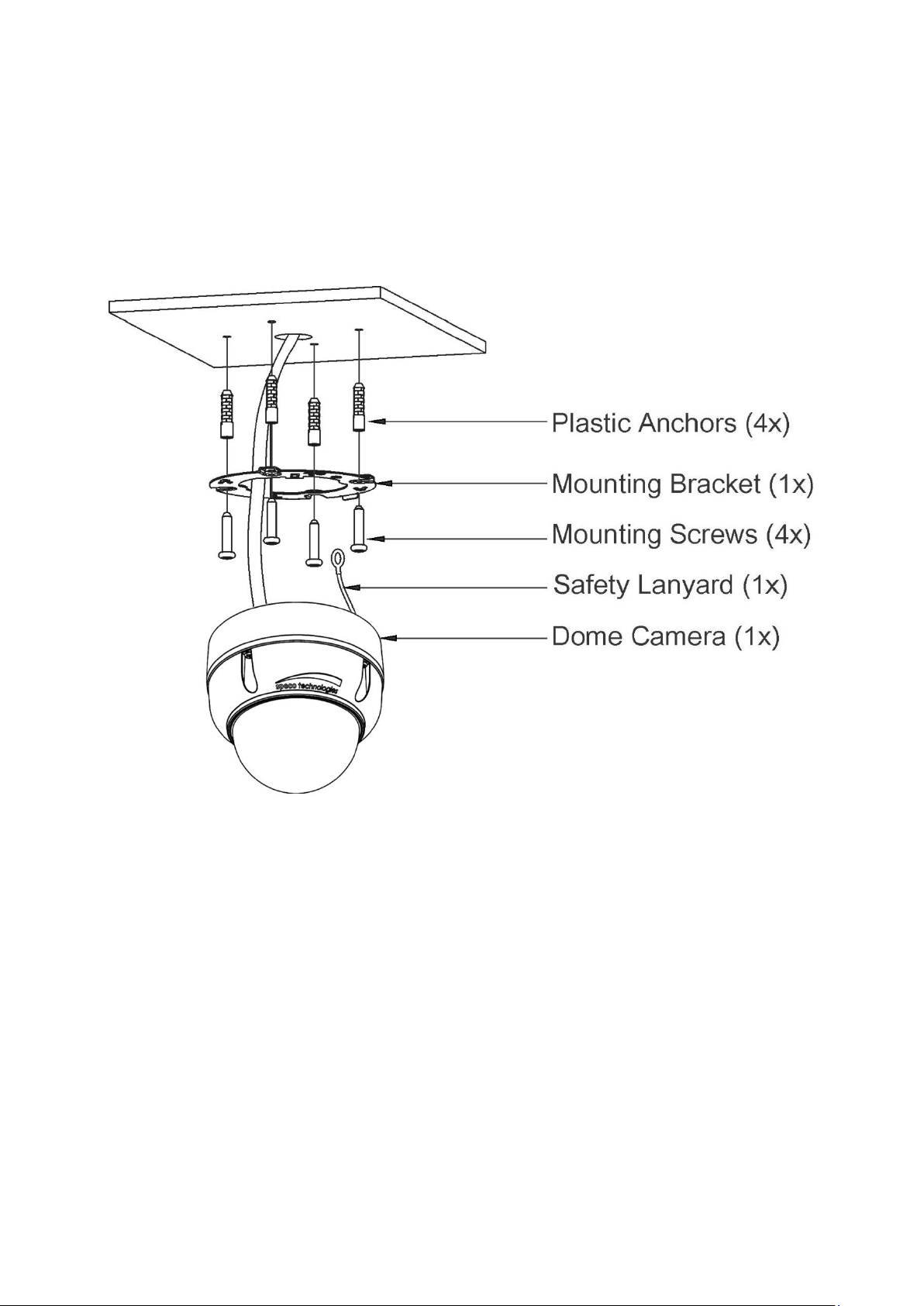
2.2.1 Locking the Camera
1. Make screw holes on the ceiling using the supplied mounting Template Sheet (Figure A).
2. Fix the Mounting Bracket to the ceiling using supplied Anchors (4x) and Mounting Screws (4x)
(Figure B).
3. Hook up the Safety Lanyard to the Safety Lanyard Hook of the Mounting Bracket (Figure C).
4. Align the locking tab on the bracket and the locking slot on the base of the dome (Figure D).
5. Turn the dome to the counterclockwise about 10 degree to the locked position (Figure E).
9
Page 10
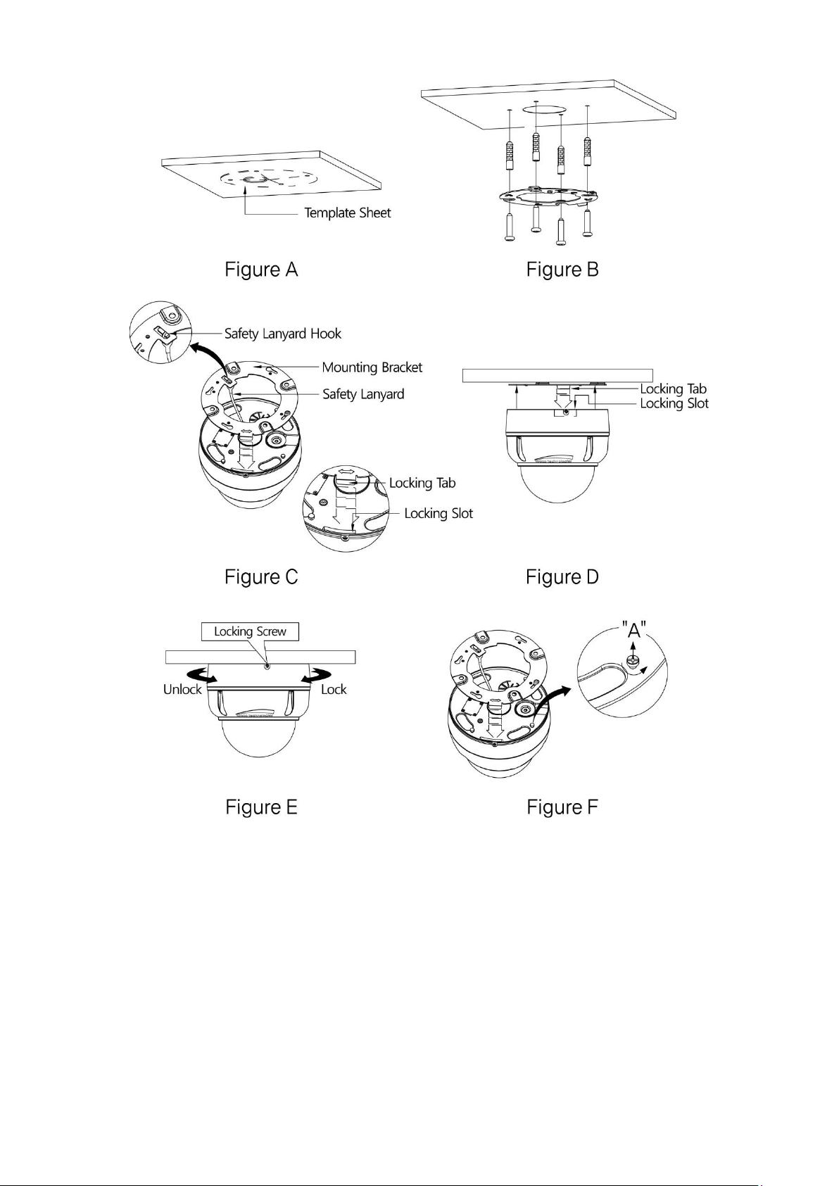
CAUTION: Before installing mounting bracket to surface pre-adjust the four mounting
screws "A" on the base of the dome camera to best match the mounting bracket
locked position. Unscrew the locking screw on the side of the dome's base and
fit the tab of the mounting bracket into the locking slot. Screws "A" should not
be too tight or too loose when the dome is in the locked position. After setting
the proper positions of screws "A" remove the mounting bracket and install it to
the proper surface. If it is too difficult to lock the dome in position after the
mounting bracket has been installed readjust the screws "A" by unscrewing
them a small amount and try to install dome camera again.
10
Page 11
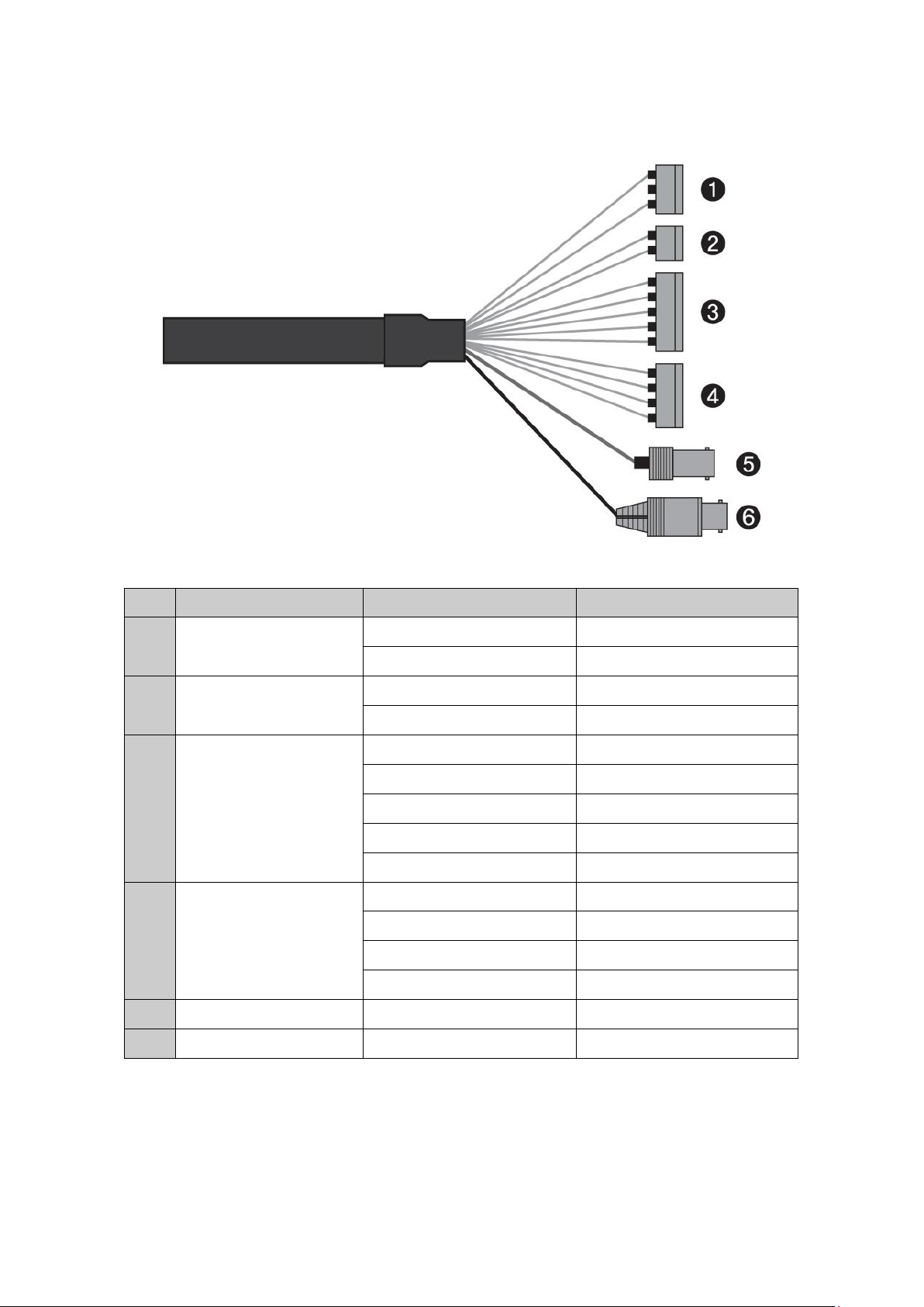
2.3 Basic Configuration of Dome Camera System
No.
Connector
Wire Color
Description
1
3-pin terminal block
RED
24VAC or 12VDC+
WHITE
24VAC or 12VDC-
2
2-pin terminal block
GREEN
RS-485+
BLUE
RS-485-
3
5-pin terminal block
GRAY
ALARM INPUT 1
VIOLET
ALARM INPUT 2
ORANGE
ALARM INPUT 3
SKY BLUE
ALARM INPUT 4
BLACK
GND
4
4-pin terminal block
YELLOW
ALARM OUTPUT 1
BLACK & WHITE
GND
SKY BLUE & BALCK
ALARM OUTPUT 2
ORANGE & BLACK
GND
5
BNC jack
BLUE
HD-TVI OUTPUT
6
BNC jack
BLACK
CVBS OUTPUT
The dome camera must be installed by qualified service personnel in accordance with all local and
federal electrical and building codes.
11
Page 12
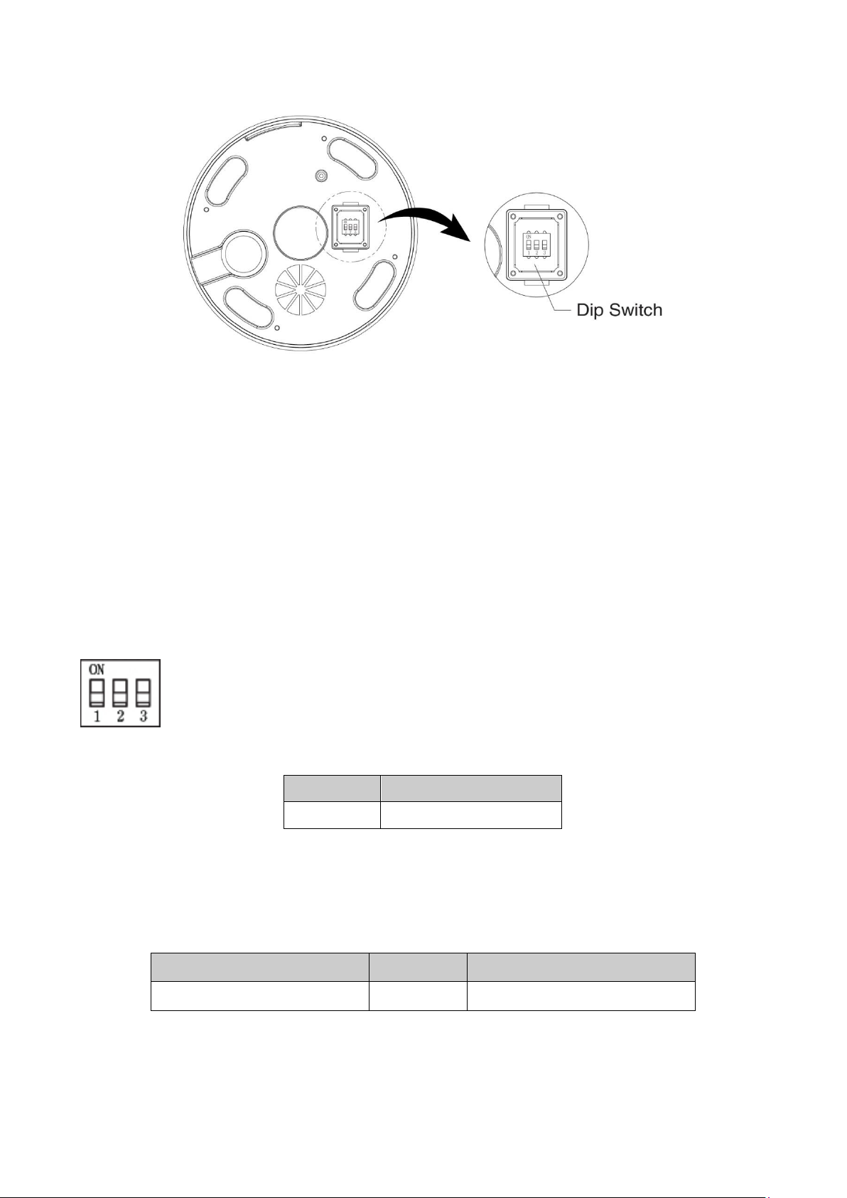
S1-D1
Video Signal
OFF
HD-TVI OUTPUT
S1-D2
S1-D3
HD-TVI OUTPUT
ON
OFF
Speco-C
NOTE: Open the DIP switch cover and change the setting of DIP switch.
The cover should be closed after setting DIP switch.
2.4 Setting Dome Camera Address (ID)
To prevent damage, each dome camera must have a unique address (ID).
The factory default setting is 1.
Refer to ‘3.11 Dome Communication’ section for detailed information.
2.5 Setting Dome Camera Video Signal & Coaxitron Protocol
S1
You can set video signal with D1 in S1.
You can set coaxitron protocol with D2 and D3 in S1.
12
Page 13

2.6 Connections
• Connecting to the RS-485
The dome camera can be controlled remotely by an external device or control system, such as a
control keyboard, using RS-485 half-duplex serial communications signals.
• Connecting HD-TVI Output connector
Connect the HD-TVI output (BNC) connector to the monitor or video input.
• Connecting CVBS Output connector
Connect the CVBS output (BNC) connector to the monitor or video input.
• Connecting Alarms
- A1,A2,A3,A4 (Alarm Input 1,2,3,4)
You can use external devices to signal the dome camera to react on events. Mechanical or
electrical switches can be wired to the A1,A2,A3,A4 (Alarm Input 1,2,3,4) and G (Ground)
connectors.
See Chapter 3 — Program and Operation for configuring alarm input.
- G (Ground)
NOTE: All the connectors marked G or GND are common.
Connect the ground side of the alarm input and/or alarm output to the G (Ground) connector.
- AO1,AO2 (5VTTL Alarm Output 1,2)
The dome camera can activate external devices such as buzzers or lights. Connect the device
to the AO1,AO2 (Alarm Output 1,2) and G (Ground) connectors.
See Chapter 3 — Program and Operation for configuring alarm output.
• Connecting the Power
Connect power of 12VDC or 24VAC for the dome camera.
When using a 12VDC adapter, connect the positive (+) pole to the ‘+’ position and
the negative (-) pole to the ‘-’ position.
Use satisfy clause 2.5 of IEC60950-1/UL60950-1 or Certified/Listed Class 2 power source only.
13
Page 14

2.7 Getting Started
001 AF AE
EMPTY DATA
ALARM:1
DOMEID:0001
360.0 090.0
INFORMATION
DISPLAY
CAMERA TITLE & ID
PAN & TILT ANGLE
FUNCTION TITLE
STATUS of
FOCUS and AE
ALARM DISPLAY
Once installed apply power to the dome camera. The dome camera will start a configuration
sequence.
OSD Position
14
Page 15

Chapter 3 — Program and Operation
DOME MENU
AUTO SCAN
PRESET
TOUR
PATTERN
PRIVACY ZONE
CAMERA
DOME COMMUNICATION
ALARM
DOME SETUP
EXIT(ESC TO EXIT)
Function
Button
Call the On-screen menu utility.
MENU
Navigate through the menu items.
Joystick up or down
Go into the sub-menu items.
Joystick left or right or IRIS Open
Change value.
Enter the editing title mode.
Joystick left or right or
Zoom handle twist or Tele , Wide
Change value of angle.
CTRL + Joystick
Enter the changing angle mode.
IRIS Open
Exit the changing angle mode.
IRIS Close
Escape (EXIT)
ESC
3.1 Dome Camera Selection
Before you program or operate a dome camera, you must select the dome camera by pressing
No. + CAM keys.
Example: Pressing 1 , 0 + CAM keys sequentially will select dome camera 10. The selected
dome camera ID will be displayed on the LCD monitor of the keyboard controller.
3.2 Accessing the On-Screen Menu Utility
You can call up the On-screen menu utility on your monitor by pressing the MENU key on the
keyboard controller, the following On-screen menu utility will appear:
3.3 How to control the On-Screen Menu Utility
15
Page 16

3.4 Auto Scan (Shortcut: SCAN)
AUTO SCAN SETUP
NUMBER : 01
TITLE : A01
MODE : NORMAL
SPEED : 5 STEP
START ANGLE : ----- ----END ANGLE : ----- ----SCAN DIR : CCW
SWAP : OFF
DWELL : 03 SEC
FOCUS : AUTO
SAVE AND EXIT(ESC TO CANCEL)
TITLE EDIT MENU
(CTRL KEY)
A01
*
A B C D E F G H I J
K L M N O P Q R S T
U V W X Y Z 0 1 2 3
4 5 6 7 8 9 ( )
ALL DELETE
EXIT(ESC TO EXIT)
The Auto Scan supports up to 17 programmed angles at user-programmable speeds.
NUMBER 01 ~ 08, 10 ~ 17, 09: AUTO-PAN mode.
TITLE up to 6 characters
MODE NORMAL, VECTOR, RANDOM (AUTO-PAN mode: NORMAL, RANDOM only).
NORMAL Move from start point to end point in panning only
VECTOR Move from start point to end point including tilt and zoom simultaneously and
linearly.
RANDOM Move randomly between the start point and the end point
SPEED 1 ~ 13 step, the lower number means the slower speed.
SCAN DIR Set the Scan direction, CCW (Counter Clock Wise), CW (Clock Wise).
SWAP Swaps the start point for the end point.
DWELL Set the dwell time at the both end, 01 ~ 99 seconds.
FOCUS AUTO, MANUAL
Follow these steps to program Auto Scan:
1. Press the SCAN key to enter the Auto Scan menu directly. Or press the MENU key to display
the main menu on the monitor. Scroll to Auto Scan and push the Joystick to the right.
2. Select “NUMBER” and set the desired number by pushing the Joystick to the left or right.
3. Select “TITLE” and twist the Joystick to enter the title edit mode.
4. Twist the Joystick to change the alphanumeric characters and move the next position by
pushing the Joystick to the left or right. Or move down to the character table and press the
CTRL or IRIS Open key at the desired character then the cursor position moves to the next
position automatically. Push the Joystick to the left or right at the “ALL DELETE” field to delete
all characters. Push the Joystick to the left or right at the “EXIT” field to finish title edit menu.
16
Page 17

5. Select “MODE” and “SPEED”.
AUTO SCAN AREA SETUP
(CTRL KEY)
NUMBER 01
START : ----- ----END : ----- ----EXIT(ESC TO EXIT)
6. Select “START ANGLE”. Hold down the CTRL key while selecting the start position using the
Joystick. Current panning position will be displayed. Release the CTRL key to complete the
selection of the start position. Or press the IRIS Open key then the “CONTROL” displays. Move
the desired position and the zoom position. Press the IRIS Close key then the “CONTROL”
disappears. To adjust at the 0.1 degree interval, twist the Joystick at the pan field and the tilt
field.
7. Select “END ANGLE”. Hold down the CTRL key while moving the Joystick to select the end
position. The end position angle should be larger than start position. Release the CTRL key to
complete the selection of the end position. Or press the IRIS Open key then the “CONTROL”
displays. Move the desired position and the zoom position. Press the IRIS Close key then the
“CONTROL” disappears. To adjust at the 0.1 degree interval, twist the Joystick at the pan field
and the tilt field.
8. Set “SCAN DIR” to CCW or CW.
9. Select “SWAP”, Set to ON to exchange the start angle and the end angle.
10. Set “DWELL time”.
11. Set “FOCUS”.
12. Select “SAVE AND EXIT” and push the Joystick to the right or press the IRIS Open key.
Press the ESC or IRIS Close key to exit the program without saving.
NOTE: Pressing the HOME key delete stored data at the angle field.
To set the position using the Preset position:
a. Before entering the Auto Scan menu, select a Preset position as a starting point for Auto Scan.
Example: 2 + PRST keys and do step 1 to 5. In step 6, just press the CTRL key at the start
angle position, the current position will be displayed as a start position.
b. Save and Exit from the menu.
c. In normal mode, call a Preset to be the end point of Scan. Press 3 + PRST keys then press the
SCAN key to enter the Auto Scan menu. Move the cursor position to END ANGLE. Just press
the CTRL key at the end angle position. Save and exit from the menu.
Press the SCAN key on the angle field to display with the small OSD. Then the screen will show
as below.
The setting procedure is the same as above.
NOTE: 09: AUTO-PAN mode (endless panning)
17
Page 18

3.5 Preset (Shortcut: PRST)
PRESET SETUP
NUMBER : 001
TITLE : -----CAMERA SET
DWELL : -- SEC
1 2 3 4 5 6 7 8 9 0
- * - - - - - - - -
- - - - - - - - - -
- - - - - - - - - NEXT PAGE
SAVE AND EXIT(ESC TO CANCEL)
PRESET CAMERA SETUP
FOCUS : AUTO
MOTION: OFF
MOTION SETUP
AE SETUP
SAVE AND EXIT(ESC TO CANCEL)
If you need to view specific places routinely, you should program Presets. A Preset is a
programmed video scene with automatic pan, tilt, zoom, focus, and AE settings. Once
programmed, placing the number position and pressing the PRST key on your controller calls up
that Preset automatically. In addition, Presets may be assigned the “home” position for the dome
camera. As many as 240 Presets, whose positions are saved in the dome’s firmware, may be
programmed.
There are eight pages of Preset menu. Each page has 30 Presets. Pages can be scrolled by
pushing the Joystick to the left or right on the first or last No. of Preset.
- Blank Preset position
* Position has the Preset
! Current cursor position
Follow steps below to store the Preset positions:
1. Press the PRST key to enter the Preset menu directly. Or press the MENU key to display the
main menu on the monitor. Scroll to Preset and push the Joystick to the right.
2. Select the blank Preset position to be stored by pushing the Joystick up, down, right, or left.
3. After selecting a blank position, press and hold the CTRL key. Use the Joystick to control the
direction of the camera and lens.
4. After aiming the camera (view direction and lens control), release the CTRL key. The cursor will
be on the “TITLE” after saving data then twist the Joystick or press the Tele or Wide key to
edit the Preset title. Follow the procedure of the Auto Scan above to edit titles.
5. Select “CAMERA SET” and push the Joystick to the left or right. Then the Preset camera setup
displays.
Set FOCUS AUTO, MANUAL, ONE PUSH
Set MOTION OFF, ON
18
Page 19

Select “MOTION SETUP” and push the Joystick to the left or right. Then the MOTION setup
MOTION SETUP
SENSITIVITY: 10
POSITION : ALL
DELAY : 00 SEC
OUTPUT : OFF
HOLD TIME : 03 SEC
EXIT(ESC TO EXIT)
PRESET AREA SETUP
(CTRL KEY)
NUMBER 001
PAN TILT
000.0 000.0
EXIT(ESC TO EXIT)
displays.
Set SENSITIVITY 00 ~ 20
Set POSITION ALL, CENTER
Set DELAY 00 ~ 05 seconds
Set OUTPUT OFF, OUT1, OUT2
Set HOLD TIME 03 ~ 99 seconds
Select “AE SETUP” and push the Joystick to the left or right. Then the AE setup displays.
Refer to the AE SETUP in the camera setup.
6. Set “DWELL time”. (03 ~ 99 seconds)
7. To select the next page of Presets, scroll the page by pushing the Joystick to the left or right on
the first or last columns of the menu.
8. Repeat step 2 through 7 for each additional Preset position.
9. Select “SAVE AND EXIT” and push the Joystick to the right or press the IRIS Open key. Press
the ESC or IRIS Close key to exit the program without saving.
NOTE: Press the HOME key at programmed Preset position (*) to delete a programmed
Preset view.
The position, which is marked with the *, already has the Preset view assigned. Press the PRST
key on the * to review the stored Preset. The camera will show the stored Preset scene.
Hold down the CTRL key while selecting the desired scene using the Joystick. Current position
will be displayed. Release the CTRL key to complete. Or press the IRIS Open key then the
“CONTROL” displays. Move the desired position and the zoom position. Press the IRIS Close key
then the “CONTROL” disappears. Select “EXIT” and push the Joystick to the right.
19
Page 20

3.6 Shortcut of Preset Program
TOUR SETUP
NUMBER : 01
TITLE : T01
SCAN TYPE : NORMAL
SPEED : -- STEP
TOUR FUNC
SAVE AND EXIT(ESC TO CANCEL)
TOUR FUNC SETUP
(CTRL KEY)
DWELL : -- SEC
003 A04 --- --- ---
--- --- --- --- ---
--- --- P01 --- ---
--- T02 --- --- ---
--- --- --- --- ---
--- --- --- --- ---
--- --- --- --- ---
--- --- --- --- --EXIT(ESC TO EXIT)
After selecting the desired scene, press No. (1 to 240), and press the CTRL and PRST keys
subsequently. The current view will be stored to the selected Preset number if the Preset number
is empty. If selected Preset number is not empty, “OVER WRITE” message will be displayed on
the monitor and select the “OK” and push the Joystick to the right to overwrite.
Example: 1 , 0 , 1 + CTRL + PRST keys will store current view as Preset no. 101. In this case,
focus will be programmed as Auto, dwell time will be set to 3 second, and the current
AE mode will be programmed.
3.7 Tour (Shortcut: TOUR)
There are 8 programmable Tours. Each Tour consists of up to 40 Preset positions, Patterns, Scans
or other Tours (second-level). Using second-level Tours, it can be expanded to over 300 functions
in a single Tour.
--- Blank position
SCAN TYPE NORMAL, VECTOR
DWELL 03 ~ 99 seconds
003 Preset (1 ~ 240)
A04 Auto Scan (1 ~ 8, 10 ~ 17)
P01 Pattern (1 ~ 8)
T02 Tour (1 ~ 8)
Follow the steps below to program the Tours:
1. Press the MENU key to display the main menu on the monitor. Scroll to Tour and push the
2. Select “NUMBER” and set the desired number by pushing the Joystick to the left or right.
3. Choose a blank position to be programmed by pushing the Joystick up, down, right, or left.
Joystick to the right to enter the Tour menu. Or just press the TOUR key on the keyboard.
20
Page 21

4. To add a stored Preset, twist the Joystick then the stored Preset number displays.
5. To place functions other than Preset, press the TOUR, PTRN or SCAN keys for Tour, Pattern
or Auto Scan respectively.
6. You can also overwrite the programmed number and remove a stored number from the Tour,
press the HOME key on the stored number, a blank position mark (---) will be displayed.
7. Repeat step 2 through 6 for each desired position. Each title will be displayed on top of the line.
8. To edit the “TITLE”, follow the procedure of the Auto Scan above to edit titles.
9. Select “SAVE AND EXIT” and push the Joystick to the right or press the IRIS Open key. Press
the ESC or IRIS Close key to exit the program without saving.
You can expand the Tour sequence by calling other programmed Tours.
NOTE: The speed applies in the vector mode only.
NOTE: In the Tour mode, in conjunction with Preset and Auto Scan, you can make the
camera travel from a Preset position to another Preset position at a specific speed.
Example: Preset 001>002>003>004>005>006, Auto Scan 01 starts at Preset 002, ends at
Preset 003, Auto Scan 02 starts at Preset 005, ends at Preset 006;
Tour 001, 002, A01, 004, A02.
1 2 2~3 4 5~6, repeat
where : Quick move, ~ : Programmed speed
To change the dwell time of the Preset in the Tour:
Use the Joystick to move the cursor to a stored Preset position.
By pressing the PRST key, the camera will move to the stored Preset view and the cursor moves
to the dwell time field.
After changing the dwell time, press the PRST key and the cursor moves to the Preset number.
To assign the functions other than Preset in the Tour when the function key is not
existed:
Use the Joystick to move the cursor to a stored Preset position.
Pressing the CTRL or IRIS Open key will change the Preset number to other function (Auto Scan,
Pattern, Tour or Preset) with the first programmed number.
To change the number, twist the Joystick or press the Tele or Wide key.
21
Page 22

3.8 Pattern (Shortcut: PTRN)
PATTERN SETUP
(CTRL KEY)
NO TITLE SEC PERCENT
1 : P01 000 00.0%
2 : P02 000 00.0%
3 : P03 000 00.0%
4 : P04 000 00.0%
5 : P05 000 00.0%
6 : P06 000 00.0%
7 : P07 000 00.0%
8 : P08 000 00.0%
SAVE AND EXIT(ESC TO CANCEL)
PATTERN AREA SETUP
(CTRL KEY)
NUMBER 01
000 00.0%
EXIT(ESC TO EXIT)
The Pattern feature records user control of the selected dome camera. Up to 8 Patterns can be
stored and played back by pressing No. + PTRN keys subsequently.
Follow steps below to program the Pattern:
1. Press the MENU key to display the main menu on the monitor. Scroll to Pattern and push the
Joystick to the right to enter the Pattern menu. Or just press the PTRN key on the keyboard.
2. Select the desired Pattern to be programmed by pushing the Joystick up or down. If the Pattern
is not 000, a Pattern has already been recorded. Patterns can be overwritten.
3. Press and hold down the CTRL key while controlling the camera direction and zoom with the
Joystick. The dome will be automatically recorded until you release the CTRL key. Or press the
IRIS Open key then the “CONTROL” displays. Move the position and the zoom position. Press
the IRIS Close key then the “CONTROL” disappears.
4. To edit the “TITLE”, follow the procedure of the Auto Scan above to edit titles.
5. Select “SAVE AND EXIT” and push the Joystick to the right or press the IRIS Open key. Press
the ESC or IRIS Close key to exit the program without saving.
NOTE: Press the HOME key at any programmed position to delete the Pattern.
NOTE: If Pattern recording time reaches 500 seconds, it will automatically stop for a
moment.
Press the PTRN key on the title field to display with the small OSD. Then the screen will show as
below.
The setting procedure is the same as above.
22
Page 23

3.9 Privacy Zone
PRIVACY ZONE SETUP
(CTRL KEY)
NO METHOD COLOR
01 ON BLOCK BLACK
02 ON BLOCK BLACK
03 OFF ----- BLACK
04 OFF ----- BLACK
NEXT PAGE
SAVE AND EXIT(ESC TO CANCEL)
PRIVACY AREA MENU
(CTRL KEY)
NUMBER 01
354.8 344.8
EXIT(ESC TO EXIT)
Hide up to 16 unwanted scenes in a camera.
There are four pages of Privacy Zone menu. Each page has 4 Privacy Zones.
1. Place the cursor at the field.
2. Hold down the CTRL key displays the privacy area menu while selecting the position using the
Joystick. Current position will be displayed. Release the CTRL key to complete the selection of
the position. Or press the IRIS Open key then the privacy area menu displays. Move the desired
position. Press the IRIS Close key then the “CONTROL” disappears.
To adjust the size, twist the Joystick or press the Tele or Wide key.
Returns to the previous menu.
3. To turn the stored zone ON or OFF, twist the Joystick or press the Tele or Wide key.
4. Set the “COLOR”: “BLACK”, “WHITE”, “YELLOW”, “CYAN”, “GREEN”, “MAGENTA”, “RED” or
“BLUE”.
5. Select “SAVE AND EXIT” and push the Joystick to the right or press the IRIS Open key. Press
the ESC or IRIS Close key to exit the program without saving.
NOTE: Press the HOME key to delete programmed Privacy Zone at the off/on field.
23
Page 24

3.10 Camera Menu
CAMERA SETUP
FOCUS CONTROL
WB CONTROL
AE CONTROL
CAMERA CONTROL
SHARPNESS : 03
DIGITAL ZOOM : OFF
IMAGE FLIP : OFF
PRESET FREEZE : OFF
RESOLUTION : 1080P/25
SAVE AND EXIT(ESC TO CANCEL)
FOCUS SETUP
MODE : AUTO
SENSITIVITY : MID
FOCUS LIMIT : 1M
SAVE AND EXIT(ESC TO CANCEL)
SHARPNESS The higher the value, the more edges in the picture will be enhanced.
(0 ~ 10)
DIGITAL ZOOM OFF: Zoom range is limited to the optical.
2X: Zoom is extendable up to 2X of digital range.
4X: Zoom is extendable up to 4X of digital range.
8X: Zoom is extendable up to 8X of digital range.
MAX: Zoom is extendable Max digital zoom range.
IMAGE FLIP This function turns the video output from the camera upside down and
reverses it horizontally.
This option is helpful to install in the opposite side.
PRESET FREEZE ON: the image is frozen during calling Preset.
RESOLUTION HD-TVI Output: 1080P/30, 1080P/25, 720P/60, 720P/50, 720P/30, 720P/25
• FOCUS CONTROL
MODE AUTO, MANUAL, ONE PUSH, CONST MANUAL
Use manual mode in normal use.
SENSITIVITY LOW, LOW.MID, MID, MID.HIGH, HIGH
FOCUS LIMIT This distance is approximate value and the focus operates from the setting
value.
CAUTION: Avoid continuous, 24-hour use of the auto focus. This will shorten the lifespan
of the lens.
24
Page 25

• WB (White Balance) CONTROL
WB SETUP
MODE : AUTO
R GAIN : --B GAIN : --SAVE AND EXIT(ESC TO CANCEL)
AE SETUP
MODE : AUTO
DSS : OFF
IRIS : AUTO
SHUTTER : AUTO
BRIGHT : 10
GAIN LIMIT : 07
NIGHT SHOT : AUTO
ADDITIONAL AE
SAVE AND EXIT(ESC TO CANCEL)
MODE AUTO, MANUAL, INCANDESCENT, FLUORESCENT, OUTDOOR
AUTO Computes the white balance value output using color information
from the entire screen automatically.
INCANDESCENT Auto white balance mode that is compatible with incandescent lamps.
FLUORESCENT Auto white balance mode that is compatible with fluorescent lamps.
OUTDOOR Outdoor white balance mode
MANAUL Manual mode, you can change R and B Gain manually.
R GAIN 0 ~ 255
B GAIN 0 ~ 255
R GAIN / B GAIN modes are controllable only in MANUAL Mode.
• AE CONTROL
MODE AUTO, MANUAL, I.PRIO, S.PRIO
AUTO Auto exposure mode
MANUAL Variable Iris, Shutter speed
I.PRIO Variable Iris, Auto Shutter speed
S.PRIO Variable Shutter speed, Auto Iris
DSS OFF, x2 ~ x8
IRIS F1.8 ~ F32
SHUTTER 1/25 (30) ~ 1/30000
BRIGHT 0 ~ 20
GAIN LIMIT 0 ~ 7
NIGHT SHOT AUTO, ON, OFF, GLOBAL
NOTE: Values in ( ) are for NTSC Camera.
25
Page 26

The NIGHT SHOT option removes the IR cutoff filter of the camera and makes the camera
ADDITIONAL AE SETUP
ACE : OFF
WDR : OFF
WDR WEIGHT : -BLC : OFF
HLC : OFF
HLC LEVEL : -HLC COLOR : --DEFOG : OFF
EXIT(ESC TO EXIT)
CAMERA CONROL
D->N LEVEL : 070
N->D LEVEL : 030
D/N DELAY : 03 SEC
CHROMA : 08
GAMMA : 2
DNR : MID
DIS : OFF
SAVE AND EXIT(ESC TO CANCEL)
sensitive to near infrared.
AUTO Camera goes in to B&W mode at low light.
GLOBAL Controlled by the keyboard
(NOTE: GLOBAL function operates F2E protocol only)
The operator can enable NIGHT SHOT for all dome cameras at the same time.
If the NIGHT SHOT mode is set to GLOBAL, “999” + ENTER will turn Off the NIGHT SHOT
mode and “888” + ENTER will turn On the NIGHT SHOT mode.
ON B/W mode
OFF Color mode
NOTE: AUTO in NIGHT SHOT function is not applied in “MANUAL” mode of AE Control.
ADDITIONAL AE
ACE OFF, LOW, MID, HIGH
WDR OFF, ON, NIGHT OFF (NOTE: When ON, BLC will be disabled.)
WDR WEIGHT LOW, MID, HIGH
BLC OFF, ON (NOTE: When ON, WDR will be disabled.)
HLC OFF, ON
HLC LEVEL 0 ~ 20
HLC COLOR BLACK, WHITE, YELLOW, CYAN, GREEN, MAGENTA, RED, BLUE
DEFOG OFF, ON
• CAMERA CONTROL
D->N LEVEL 0 ~ 255
N->D LEVEL 0 ~ 255
D/N DELAY 1 ~ 60 seconds
CHROMA 0 ~ 20
GAMMA 0 ~ 4
DNR OFF, LOW, MID, HIGH
DIS OFF, ON
26
Page 27

3.11 Dome Communication
DOME COMMUNICATION
*
DOME ID : 0001
PROTOCOL : AUTO
BAUDRATE : 9600
PARITY : NONE
TERMINATION : OFF
SAVE AND EXIT(ESC TO CANCEL)
To prevent damage, each dome camera must have a unique address (ID).
The factory default setting is 1.
DOME ID 1 ~ 3999
PROTOCOL AUTO, F2/F2E, PELCO-PD
BAUDRATE 2400, 4800, 9600, 19200, 38400 bps
PARITY NONE, EVEN, ODD
TERMINATION (RS-485) OFF, ON
27
Page 28

3.12 Alarm
ALARM SETUP
(CTRL KEY)
NO PRI FUN IN OUT HLD LATCH
1 1 001 NO OUT1 03 OFF
2 1 --- OFF OFF 03 OFF
3 1 --- OFF OFF 03 OFF
4 1 --- OFF OFF 03 OFF
DWELL : 03 SEC
ALARM OUT SETUP
SAVE AND EXIT(ESC TO CANCEL)
ALARM OUT SETUP
OUT1 : ALARM
OUT2 : 1 MIN
EXIT(ESC TO EXIT)
NO (Number) alarm input number
PRI (Priority) the lower number has higher priority (0 ~ 4)
FUN (Function) Stored function number to be called by alarm.
IN (Input) NO/NC – normally open/closed, OFF – ignore
OUT (Output) OUT1 ~ OUT2 – 5VTTL output, OFF – no output
HLD (Hold) Alarm will be held for programmed time. (03 to 99 seconds)
LATCH ON – Alarm message will remain on the screen even though alarm input is
deactivated.
OFF – Alarm message will disappear from the screen after programmed
hold time when alarm input is deactivated.
DWELL means the dwell time during multiple alarms, 03 to 99 seconds.
ALARM: alarm output is operated during an alarm operation or by the short key of our
keyboard.
1 ~ 5 MIN (minute): alarm output is operated during this setting time only by the function run
of the dome menu or the short key of our keyboard.
NOTE: This 1 ~ 5 MIN setting is not operated by an alarm.
There are 5 levels of priority. The function can be selected by Preset, Auto scan, Pattern or Tour
and “0” is the highest priority. Lower priority alarms won’t be serviced until the higher priority
alarm is completed. Equal priority alarms will be serviced repeatedly with the dwell time.
28
Page 29

3.13 Dome Setup
CONFIGURATION MENU
HOME FUNCTION SETUP
VIEW ANGLE SETUP
ORIGIN OFFSET
FACTORY DEFAULT
DOME RESET
OSD DISPLAY
SYSTEM SETUP
FUNCTION RUN
SYSTEM INFORMATION
EXIT(ESC TO EXIT)
HOME FUNCTION SETUP
FUNCTION : NONE
NUMBER : --WAITING TIME : 120 SEC
ENABLE : OFF
SAVE AND EXIT(ESC TO CANCEL)
• HOME FUNCTION SETUP
FUNCTION NONE, TOUR, PATTERN, AUTO SCAN, PRESET
NUMBER --WAITING TIME 10 ~ 240 seconds
ENABLE ON, OFF
The Home Function can be set so that the camera automatically goes to Tour, Pattern, Auto
Scan or Preset after the keyboard controller has been idle for a specified amount of time.
For example, if the controller is idle for 120 seconds, the camera goes to Preset 1.
Follow these steps to program the Home position:
1. Select “FUNCTION” by pushing the Joystick to the left or right to scroll through the None,
Tour, Pattern, Auto Scan or Preset functions.
2. Select “NUMBER” and push the Joystick to the left or right. The recorded function number
will scroll.
3. Select “WAITING TIME” and push the Joystick to the left or right to select from 10 to 240
seconds.
4. Select “ENABLE” and turn to ON or OFF by pushing the Joystick to the left or right.
29
Page 30

• VIEW ANGLE SETUP
VIEW ANGLE SETUP
PANNING RANGE
FLIP : 90
TILT ANGLE LIMIT : 10
SAVE AND EXIT(ESC TO CANCEL)
PANNING RANGE SETUP
(CTRL KEY)
RIGHT LIMIT : 000.0
LEFT LIMIT : 000.0
ENABLE : OFF
SWAP : OFF
AUTO PAN : ON
SAVE AND EXIT(ESC TO CANCEL)
FLIP OFF, AUTO, 90, 100, 110, 120
OFF: The dome camera moves until 90 vertically.
AUTO: When the camera reaches the floor directly above the moving object, it will stop.
At that time, release the Joystick instantly and pull it down again to run the auto-flip
function. When you use the panning range, it is recommended to use the flip mode to AUTO.
90, 100, 110, 120: Allows the image to flip digitally when the camera moves over the
setting angle vertically.
TILT ANGLE LIMIT 0 ~ 10
This option is designed to limit the view angle as there is some obstruction in zooming out on
specific areas of the tilt angle.
NOTE: Focus issues may occur in certain conditions.
PANNING RANGE
When the dome camera is installed near a wall, panning range can be limited by user.
1. Place the dome camera under 90 degree vertically.
2. Set “RIGHT LIMIT” by pushing the Joystick to the right.
3. Set “LEFT LIMIT” by pushing the Joystick to the left.
4. Set “ENABLE” to ON to use.
To exchange the right and the left limit, set “SWAP” to ON.
To apply limits on the auto pan (endless panning), set “AUTO PAN” to ON.
NOTE: When the flip mode is 90, 100, 110 or 120 and you moves over 90 vertically,
the panning range operates in opposite side.
30
Page 31

• ORIGIN OFFSET
OFFSET SETUP
(CTRL KEY)
PAN OFFSET : 000.0
TILT OFFSET : 000.0
ENABLE : OFF
SAVE AND EXIT(ESC TO CANCEL)
FACTORY DEFAULT
ARE YOU SURE ?
CANCEL
OK
DOME RESET
ARE YOU SURE ?
CANCEL
OK
This feature is useful to align a new dome camera exactly the same as the previously installed
dome camera.
Dome camera’s origin set and all data initialize option do not override offset values. Only the
default set option in this menu will set the offset value to zero. This can be used to avoid ceiling
obstructions.
• FACTORY DEFAULT
Select “FACTORY DEFAULT” to initialize the data.
• DOME RESET
This feature is used to re-calibrate the orientation of a selected dome camera. Origin offset value
is not affected by this function. (Offset is still valid after origin set.)
31
Page 32

• OSD DISPLAY
OSD DISPLAY SETUP
LANQUAGE : ENGLISH
TITLE : DOMEID
DOME OSD : ON
FOCUS/EXPOSURE : OFF
COLOR : YELLOW
SAVE AND EXIT(ESC TO CANCEL)
SYSTEM SETUP
MOTOR SETUP
PASSWORD EDIT
ORIGIN CHECK
CALIBRATION : ON
PASSWORD ENABLE : OFF
MENU TIMEOUT : OFF
DOME ANSWER : ON
PRESET FOCUS : AUTO
SAVE AND EXIT(ESC TO CANCEL)
LANGUAGE Select the desired language.
TITLE up to 6 characters
DOME OSD ON, POSITION, ON(ZOOM), ZOOM, OFF
All display or title will disappear when DOME OSD DISPLAY is set to OFF.
FOCUS/EXPOSURE ON, OFF
ON: FOCUS and EXPOSURE displays. (AF AE)
COLOR YELLOW, GRAY, BLUE
• SYSTEM SETUP
CALIBRATION ON (Auto origin check), OFF
PASSWORD ENABLE ON (requires the password to enter menu), OFF
MENU TIMEOUT ON (5 minutes), OFF (always menu display)
DOME ANSWER ON, OFF (no acknowledge command from the dome)
This option is helpful to escape the collision of the command using some DVR.
PRESET FOCUS AUTO, MANUAL, ONE PUSH
This option set the default mode of the focus when you save the Preset.
32
Page 33

MOTOR SETUP
MOTOR SETUP
PROPORTIONAL P/T : ON
P/T MODE : NORMAL
SLOW PAN MAX : 40
SLOW TILT MAX : 40
NORMAL PAN MAX : 90
NORMAL TILT MAX : 90
TURBO PAN MAX : 360
TURBO TILT MAX : 100
SAVE AND EXIT(ESC TO CANCEL)
PASSWORD EDIT SETUP
(CTRL KEY)
INPUT PASSWORD
PASSWORD:
A B C D E F G H I J
K L M N O P Q R S T
U V W X Y Z 0 1 2 3
4 5 6 7 8 9 ( )
SAVE AND EXIT(ESC TO CANCEL)
Motor Setup menu provides the pan and tilt speed of a camera. User can set the desired
speed with pushing the Joystick to the left or right. During operation, pressing 153 + ON keys
will change the speed to the SLOW mode and pressing 153 + OFF keys will change the
speed to the NORMAL mode.
Press and hold the CTRL key and moving the Joystick will operate with the TURBO speed
mode.
PROPOTIONAL P/T ON, OFF
P/T MODE SLOW, NORMAL, TURBO
SLOW PAN Maximum speed 19 ~ 90/second
SLOW TILT Maximum speed 19 ~ 90/second
NORMAL PAN Maximum speed 40 ~ 360/second
NORMAL TILT Maximum speed 40 ~ 200/second
TURBO PAN Maximum speed 200 ~ 380/second
TURBO TILT Maximum speed 90 ~ 300/second
PASSWORD EDIT
You can change the password with 6-digit character in this menu.
The default password is 555555.
When the password enable is on, the input password window displays to enter the menu.
At this time, move the cursor to the desired character with the Joystick and press the CTRL
or IRIS Open key.
33
Page 34

ORIGIN CHECK
ORIGIN CHECK
ARE YOU SURE ?
CANCEL
OK
FUNCTION RUN SETUP
(CTRL KEY)
PRESET : --PATTERN : --TOUR : --SCAN : --HOME
AUTO PAN
ALARM OUT : ---EXIT(ESC TO EXIT)
If you find the dome in the wrong position during operation, execute this origin check and the
dome camera will return to the right position after the origin check operation.
Pressing 151 + ON keys will execute the origin check.
• FUNCTION RUN
This Function Run menu allows you to execute the function when you use a keyboard or a DVR
without the function keys (Preset. Pattern, Tour and Scan).
1. Select the desired Function by pushing the Joystick up or down.
2. Select the number by twist the Joystick in PRESET, PATTERN, TOUR and SCAN.
3. Press the CTRL or IRIS Open key to execute.
NOTE: To execute the function, you should save the function (PRESET, PATTERN, TOUR
and SCAN) first.
- HOME
Select “HOME” and press the CTRL or IRIS Open key. The dome camera goes to the
default position that it returns to after an assigned period of inactivity passes. The default
position may be a Preset, Tour, Pattern or no action.
- AUTO PAN
You can execute the endless auto pan to turn in one direction continuously by selecting
Auto-Pan.
- ALARM OUT
This function can operate only when the alarm out setup has the time in the alarm menu.
34
Page 35

Ex)
ALARM OUT SETUP
OUT1 : ALARM
OUT2 : 1 MIN
EXIT(ESC TO EXIT)
SYSTEM INFORMATION
CAMERA TYPE : xxxx-Vx.xx
H/W VERSION : Vx.xx-xxxx
ROM VERSION : Vx.xxxxxx
PROTOCOL : xxxx
BAUDRATE : 9600(NONE)
HD B/D VERSION : Vx.xx
EXIT(ESC TO EXIT)
You press the CTRL or IRIS Open key then that alarm out operates during the setting time
only.
• SYSTEM INFORMATION
The system information provides essential information about the dome camera if service is
required. This screen displays the camera type and ROM version. The information on this screen
cannot be modified.
35
Page 36

Appendix A — Specifications
Model
HTPTZ20T
IMAGE
Lens
20x
4.7mm ~ 94.0mm
Angle of View
55.5° (H) ~ 3.0° (H)
Image Sensor
Type
1/2.8" SONY STARVIS CMOS sensor
Pixels
1945 (H) x 1097 (V)
Min. Illumination
Color : 0.35 Lux @ 50IRE
BW : 0.013 Lux @ 50IRE
Scanning Mode
Progressive Scan
Wide Dynamic Range
True WDR
Day and Night Mode
True D/N (Auto, Day, Night)
Noise Reduction
3DNR
Digital Zoom
16x
Exposure Control
Auto, Manual, Shutter Priority, Iris Priority
White Balance Control
Auto, Manual, Incandescent, Fluorescent, Outdoor
Back Light Compensation
Yes
Image Effect
Flip (Digital)
Shutter Speed
25/30fps : Auto (1/30,000 ~ x8 sec.), Manual
50/60fps : Auto (1/50,000 ~ x8 sec.), Manual
VIDEO
Resolution
HD-TVI : 1080p @ 25/30fps, 720p @ 25/30/50/60fps
Video Output
HD-TVI Composite
DIS
Yes
Defog
Yes
PTZ Function
Pan Range
360° Endless
Pan Speed
Max. 380°/sec. (Preset)
Tilt Range
0° ~ 180°
Tilt Speed
Max. 380°/sec. (Preset)
Auto Calibration
0.1° ~ 6°
Auto Scan
1 Auto Pan & 16 Auto Scans
Preset
240
Tour
8
Pattern
8
Home Function
Yes
Privacy Mask Zone
16 Programmable Zones
EXTERNAL IN/OUT
Video HD-TVI Output
BNC Jack
Video Composite Output
BNC Jack
Alarm
4 Inputs, 2 Outputs (Terminal Block)
Control
RS-485, Baud Rate: 2400 ~ 38400 bps (Default: 9600 bps)
ID (Camera Address)
1 ~ 3999
20x HD-TVI PTZ CAMERA
36
Page 37

ETC
Operating Humidity
0 ~ 90%RH (Non-condensing)
Operating Temperature
-10C ~ 50C
Power Supply
12VDC, 24VAC
Power Consumption
1.0A (12.0W) @ 12VDC, 24VAC
Dimensions
See dimension drawing
Net Weight
Approx. 1.6kg
Ingress Protection
IP66
* Specifications are subject to change without notice *
Figure – Dimension
37
Page 38

Appendix B — Troubleshooting
Problem
Possible Solution
No video.
Verify that power is connected to all pieces of equipment
in the system.
Verify that the power switches are in the ON position.
Check the video connections.
Poor video quality.
Check that the BNC connectors are inserted properly.
Check the voltage level of the dome camera.
Cable for video is shielded.
Dome cameras lose their positions.
Reset the cameras using the Dome configuration menus.
Check that the dome cameras are inserted properly in
the base.
Check the voltage level of the dome camera.
Camera number does not match the
multiplexer number.
Check the camera ID and insert the BNC cable into the
proper input of the multiplexer.
If problems occur, verify the installation of the camera with the instructions in this manual and with
other operating equipment. Isolate the problem to the specific piece of equipment in the system
and refer to the equipment manual for further information.
38
Page 39

Page 40

HTPTZ20T
20x HD-TVI PTZ CAMERA
50304098A
 Loading...