

Page 1
SPEEDZONE PRO CYCLOCOMPUTER
Congratulations on your purchase and welcome to the growing number of
cyclists who are discovering a powerful new generation of bicycle computers.
Your Specialized SpeedZone®Pro has been designed to provide the best combination of performance, features, durability and ease of use and installation.
The following functions are available on
your SpeedZone Pro bicycle computer:
• SPD - Current Speed
• AVS - Average speed
• MAX - Maximum Speed
• ATM - Automatic Start/Timer
• DST - Trip Distance
• ODO - Odometer (total distance)
• ASI - +/- Average Speed Indicator
• TM - Stopwatch
• INT - Interval Timer
• CAD - Cadence
• Digital 12/24 Hour Clock
1
Page 2
• GR% - Inclinometer
• TMP – Temperature
• ALT – Altimeter
• ALT∆– Altitude climbed
This computer also features:
• Second Wheel Option
• Easy Calibration Mode
• Wireless Mounting System
• Heavy-duty abrasion resistant
pick-up wire
• Water resistant housing
• 2 Year Warranty
• Backlit LCD display
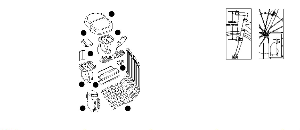
What is included in your
SpeedZone Elite package:
1. SpeedZone computer (1)
2. Mounting bracket wired for cadence (1)
3. Mounting bracket w/out cadence wiring (1)
2
1
5
2
9
4
3
7
8
6
4. Magnet with screw (1)
5. Cadence magnet (1)
6. Cable tie wraps (8)
7. Mounting bracket sizing straps (3)
8. Transmitter (1)
9. Transmitter mounting bracket (1)
MOUNTING
THE SPEEDZONE PRO
The SpeedZone Pro wireless transmitter
can mount on the right or the left side
of the fork blade. The right side should
be used on large frames or when a
suspension fork is installed. The optimal
distance between the computer and
the transmitter is 24 inches (610mm)
The distance may need to be less than
24 inches (610mm) if ambient temperatures are below 40°F (4°C). To reduce
signal loss in colder temperatures, the
transmitter should be mounted as close
FIGURE 1:
S E N S O R
P L A C E M E N T
to the computer as possible. (Maximum
mounting distance is 28 inches). Use
the transmitter-mounting bracket and
tie-wraps provided to position the
sensor. Do not tighten the tie-wraps
until final placement of the magnet is
correct. (See figure 1).
FIGURE 2:
M A G N E T
A T T A C H M E N T
3
Page 3
Attach the magnet to a spoke across
from the transmitter with the magnet
screw. The clearance between the
magnet and the transmitter should be
approximately 1/32"-1/16" (1-2mm).
Tighten the magnet and transmitter.
Do not over-tighten the magnet screw.
(See figure 2).
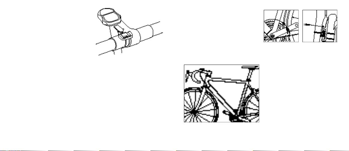
Attach the mount to the handlebar
using the bracket screw provided.
Tighten so that the bracket cannot
rotate on the handlebar. There are sev-
eral sizing straps provided to fit different diameter bars. (See figure 3).
Slide the computer forward onto the
mount until it ‘snaps’ into place with an
audible click. To remove the computer,
push it backward until it releases from
the mount. To test for proper installa-
tion of the magnet, transmitter and
4
FIGURE 3: MOUNTING BRACKET
computer, activate the computer
by pushing the ‘MODE’ (right side)
button. Pick up the front of the bicycle
and spin the front wheel. The "wheel
option" indicator will flash. If it does
not flash, check the sensor and magnet
alignment. Realign as necessary until
the "wheel option" indicator flashes
while spinning the wheel.
MOUNTING CADENCE HARDWA R E
In order to use the cadence option you
must install the mounting bracket with
the wired sensor provided with your
SpeedZone Pro. Run the cadence sensor wire along the head tube, down
tube and chain stay of your bicycle
and secure it into place using the
provided tie-wraps. (See figure 4)
FIGURE 4:
CADENCE WIRE PLACMENT
FIGURE 5:
CADENCE SENSOR
P L A C E M E N T
FIGURE 6:
CADENCE MAGNET
A T T A C H M E N T
Next, attach the cadence magnet to
the inside of your crank arm directly
across from the sensor. Use a tie-wrap
to fasten the magnet to the crank arm.
(See figure 5).
Do not tighten the tie-wrap until final
placement of the magnet is correct. The
clearance between the magnet and the
sensor should be approximately
1/32"-1/16" (1-2mm). (See figure 6)
Tighten the magnet and sensor.
5
Page 4

PROGRAMMING
Programming the functions of your
SpeedZone Pro requires it to be placed
in various "modes" (i.e. odometer
mode, distance mode). The computer
can be cycled through these modes by
pressing the "MODE" button located
on the right-hand side of the housing.
Once a specific mode has been
entered, its values can be reset or
adjusted by pressing either the
"FUNCTION" button located on the left
hand side of the housing or by using
a combination of the "MODE" and
"FUNCTION" buttons.
1. Miles or Kilometers selection
Your SpeedZone Pro will record speed
and distance in either miles (M/h) or
kilometers (Km/h). To enter your selec-
tion of miles or kilometers, push the
"MODE" button until ODO (odometer)
appears on the left side of the display
(This is called the odometer mode).
Hold down the "FUNCTION" (left side)
button and ‘tap’ the "MODE" button
once. The Km/h, m/h indicator will
begin blinking. You may now alternate
between miles and kilometers by pressing the "MODE" button. When the correct choice is flashing, select it by
pressing the "FUNCTION" button. You
will now enter the "Programmable
Odometer" mode. If the odometer setting is correct push the "FUNCTION"
button five times to exit odometer
mode. (Otherwise, see "Setting the
programmable odometer" below).
2. Setting the Programmable
Odometer
This mode is useful if you have
replaced the battery and would like to
retain the mileage you have already
ridden. To access the programmable
odometer mode, first advance the
"MODE" button until (ODO) appears
on the left-hand side of the screen.
Hold down the "FUNCTION" button
and ‘tap’ the "MODE" button once.
The Km/h indicator will flash. If the
Km/h setting is correct press the
"FUNCTION" button once and a fivedigit number will appear. You are now
in the programmable odometer mode.
To enter a mileage into the odometer,
press the "MODE" button until the
flashing digit is correct.
(Note: The "MODE" button may be
held to scroll to the correct digit.) Press
the "FUNCTION" button to select the
next digit to the right. Repeat this
process until all five digits are entered
as your existing mileage.
3. Wheel Circumference Selection
To set the circ u m f e rence for the type
of tires you are using, you can use
S p e c i a l i z e d ’s "Easy Calibration Mode"
or measure your actual tire circ u m f e rence by the rollout method. Two diff e rent tire diameters may be entered by
using the computer’s “Second Wheel
O p t i o n . ”
6
7
Page 5

Easy Calibration Mode:
Your SpeedZone Pro has been
preprogrammed with the following
14 Specialized tire sizes:
26 X 1.0 26 X 2.2
26 X 1.25 650c X 20
26 X 1.5 700c X 20
26 X 1.95 700c X 23
26 X 1.9 700c X 26
26 X 2.0 700c X 32
26 X 2.1 700c X 38
When using Easy Calibration Mode,
the SpeedZone Pro will display the tire
size on its LCD display screen. (See
figure 7) The Easy Calibration Mode is
accessed by entering the odometer
(ODO) mode and holding down the
"FUNCTION" button for three seconds.
The display will now show the currently
selected tire size for wheel option #1.
8
To scroll through the preprogrammed
tire sizes tap both the "MODE" and
"FUNCTION" buttons simultaneously.
When you reach the desired tire size
press the "FUNCTION" button once to
select it and enter Easy Calibration
Mode for wheel option #2. Follow the
same procedure to program the wheel
#2 tire size and tap the "FUNCTION"
button to exit Easy Calibration Mode.
FIGURE 7: EASY CALIBRATION SCREEN
Roll Forw a rd
S t e m
Wheel
C i rc u m f e re n c e
FIGURE 8: ROLL OUT METHOD
Roll Out Method
The roll out method will provide the
most accurate computer calibration
and can take into account variables
such as inflation pressure, rim width
and rider weight.
1. Extend a tape measure out to
3000mm (120 inches) and lock
it in place.
2. With your tire inflated to its proper
p re s s u re, place the valve at the 6:00
position (at the bottom) directly over
the start of the measuring tape.
3. Roll the wheel one complete revolution until the valve stem is again at
the 6:00 position. Read the tape
directly under the valve and note
the distance in millimeters.
(To convert inches to millimeters,
multiply inches by 25.4). Use this
number to replace the default
(default values are 2073 for wheel
one, and 2134 for wheel two)
when programming your computer.
(See figure 8)
9
Page 6

You may also use the following
quick-reference chart:
Generic Tire Size Chart
(This chart is for non-specialized tires)
26 X 1.75 2140
26 X 2.0 2074
26 X 2.1 2090
650C X 20 1945
700C X 26 2124
700C X 38 2170
Programming the circumference:
To enter the tire circumference number,
select the odometer (ODO) mode and
hold down the "FUNCTION" button for
three seconds. The display will now
show the currently selected tire size
for wheel option #1. (See figure 9)
If necessary scroll through the prepro-
grammed tire sizes by tapping both
10
FIGURE 9: CIRCUMFERENCE
PROGRAMMING SCREEN
the "MODE" and "FUNCTION" buttons
simultaneously until the display shows
a four-digit number. This number
represents your tire circumference in
millimeters. Press the "MODE" button
until the flashing digit is correct.
(Note: The "MODE" button may be
held to scroll to the correct digit.)
Press the "FUNCTION" button to
select the next digit to the right.
Repeat the process until all four digits
are entered as your tire circumference.
Press the "FUNCTION" button once to
select it and enter the circumference for
wheel option #2. Follow the same
procedure to program the wheel #2
tire size and tap the "FUNCTION"
button to exit circ u m f e rence programming mode.
4. Setting the Clock
To access the "clock mode" press and
hold the "MODE" button for three seconds. To set the clock, press the
"FUNCTION" button for three seconds.
The display will flash either twelve
(12:) or twenty-four (24:). Select
between 12: or 24: mode by pressing
the "MODE" button. Press the
"FUNCTION" button to set the mode.
The hour digit will now begin flashing.
Press the "MODE" button to adjust the
hour digits and press the "FUNCTION"
button to set. The minutes will flash
and can be adjusted by pressing the
"MODE" button. (Hold the "MODE"
button to scroll through the digits
quickly) Press the "FUNCTION" button
to set the minutes and return to clock
mode. (See figure 10)
FIGURE 10: CLOCK SCREEN
11
Page 7

5. Timer Selection
The timer can be selected for either
Automatic Timer Mode (ATM) or Timer
Mode (TM). The ATM selection allows
you to keep track of your actual riding
time. The timer only operates when the
wheel is rotating and cannot be turned
on or off manually.
The TM selection is just like a convent i o n a l stopwatch. The timer is activated
manually and records the time whether
the wheel is rotating or not. Tapping
the "FUNCTION" button starts and
stops the stopwatch and holding the
"FUNCTION" button for three seconds
will reset the stopwatch.
Note: The average speed (AVS) will
be calculated differently based upon
the selection of ATM or TM. If ATM
is selected, the AVS is based upon
only riding time. If TM is selected the
12
AVS is based on the total time the stopwatch is turned on or activated.
(See figure 11)
To select either TM or ATM, first
press the "MODE" button until either
"TM" or "ATM" appears on the lefthand side of the screen. To alternate
between "TM" and "ATM" press the
"MODE" and "FUNCTION" buttons
simultaneously. Once the desired timer
FIGURE 11: ATM/TM SCREEN
mode has been selected, press the
"FUNCTION" button to advance to the
next operating mode.
6. Interval Timer
Your Speedzone Elite is equipped with
an Interval Timer. This feature allows
you to customize your training by integrating a programmable repeating
countdown timer into your workout.
To enter the interval timer mode, pre s s
the "MODE" button until "INT" appears
on the left-hand side of the screen.
You are now in interval timer mode.
To set the interval timer, hold the
"FUNCTION" button for three seconds.
The hour digit will begin flashing. Press
the "MODE" Button until the desired
number appears. (Hold down the
"Mode" button to scroll quickly) Press
the "FUNCTION" button once to set
this number and advance to minutes.
Repeat this process until minutes and
seconds are set to the desired settings.
Press the "FUNCTION" button to exit
programming mode. Once the interval
timer is programmed, press the
" F U N CTION" button to start/stop the
countdown. (See figure 12)
Note: The shortest interval that can
be set is 5 seconds.
FIGURE 12: INTERVAL TIMER SCREEN
13
Page 8

7. Temperature
Your Speedzone Pro is equipped with
a therm o m e t e r. To enter temperature
gauge mode, press the “MODE” button
until “TMP” appears on the left-hand
side of the screen. To alternate between
°F and °C press the “FUNCTION” button.
8. Altimiter
Your Speedzone Pro contains an
ex t remely accurate altimeter that is
capable of re c o rding changes in alti-
tude in increments as small as three feet
(one meter). This altimeter calculates
altitude by precisely measuring baro-
metric pre s s u re. Due to normal changes
in barometric pre s s u re, you may need
to recalibrate your Speedzone Pro on
a daily basis. You should be able to
find the altitude where you live on a
14
topographical map or by contacting
a nearby airport.
9. Altimeter Calibration
To calibrate your altimeter press the
“MODE” button until “ALT” appears on
the left-hand side of the screen. Then
p ress the “FUNCTION” button for thre e
seconds. The first altitude digit will
begin flashing. Press the “MODE”
Button until the desired number
appears. Each push of the button will
change the altitude one-foot (or meter
if you selected metric units). Press the
“FUNCTION” button once to set this
number and advance to the next.
Repeat this process until you have
e n t e red the desired altitude. Press the
“FUNCTION” button to exit pro g r a mming mode.
FIGURE 13: AVERAGE SPEED SCREEN
Note: Altitude will be displayed in feet
when speed is measured in miles per
hour and meters when speed is measured in kilometers per hour.
10. Altitude Gained
The altitude gained function on your
Speedzone Pro calculates your total
elevation climbed. Descended altitude
is not counted.
COMPUTER FUNCTIONS
Speedometer
Speed is always indicated on the top
line of the screen. The speed is shown
continuously up to 99.9 M/h (99.9
Km/h) with a resolution of 0.1 M/h
(0.1 Km/h)
Average Speed (AVS)
The average speed is displayed on the
lower line of the screen when AVS is
shown on the left. The average speed
is based upon whether the ATM or the
TM mode has been selected, the resolution of the average speed is shown in
0.1M/h or Km/h increments.
(See figure 13)
+/- Average Speed Indicator
An up or down arrow displayed in
the upper right side of the screen
15
Page 9

FIGURE 14: MAXIMUM SPEED SCREEN
shows whether the current speed is
above or below the average speed.
Maximum Speed (MAX)
The maximum speed is displayed on
the lower line of the screen when MAX
is shown on the left. The maximum
speed is retained in memory and
updated when a higher speed is
16
attained. The maximum speed can be
reset by pressing the "FUNCTION"
button for three seconds.(Seefigure 14)
Auto Start/Stop Timer (ATM)
In ATM mode the stopwatch function
re c o rds the actual time spent riding. It
operates only when there is speed
input and is displayed on the lower
line of the scre e n .
Timer Mode (TM)
In TM mode the stopwatch function will
operate when the "FUNCTION" button
is pressed. The stopwatch will record
the total time after the button is pressed
regardless of whether there is speed
input or not. The average speed (AVS)
will be calculated based on the time
the timer mode is activated.
Interval Timer (INT)
The interval timer is displayed on the
lower line of the screen when (INT)
appears on the left. The timer indicates
the end of an interval with one short
beep per second for the last 4 seconds
of the interval. This is followed by a
long beep, indicating the beginning
of a new interval.
Cadence (CAD)
Cadence mode will display your pedaling speed in RPM’s (revolutions per
minute) on the lower line of the scre e n .
Monitoring how fast you turn your pedals can be used as a tool to enhance
the efficiency with which you ride your
bicycle. Simply put, the best cadence is
a balance between leg speed and pedal
p re s s u re. Beginning cyclists typically
p refer to pedal at a slower cadence,
FIGURE 15: CADENCE SCREEN
a round 60-rpm, while advanced cyclists
and racers are more efficient between
90 and 100 rpm. (See figure 15)
Trip Distance (DST)
Trip distance mode will re c o rd up to
999.99 miles or kilometers and then ro l l
to zero. The trip distance function can
be reset by pressing the "FUNCTION"
button for three seconds. The resolution
17
Page 10

FIGURE 16: TRIP DISTANCE SCREEN
is 0.01 miles (0.01 Kilometers). The
trip distance is shown on the lower line
if the screen. (See figure 16)
Odometer (ODO)
The odometer will record the total
distance traveled up to 99,999 miles
or kilometers and then roll to zero. The
odometer can be reset by pressing the
18
"FUNCTION" button for three seconds.
The total distance is shown on the
lower line if the screen. (See figure 17)
Inclonometer (GR%)
The inclonometer will display the
percent of grade you are climbing or
descending in increments of 1%. A
negative grade or descent is indicated
by a negative sign. (example: –4%)
FIGURE 17: ODOMETER SCREEN
Tech note: The inclinometer calculates
percentage of grade by comparing
the change in altitude to the distance
traveled. This data is updated on the
LCD display every 5 seconds and is
based upon data accumulated during
the previous 20 seconds. It is normal to
experience a slight delay when transitioning from one grade to another.
Temperature (TMP)
Your Speedzone Pro is equipped with
a thermometer. Temperature can be
displayed in either °F or °C.
Programmable Odometer
The odometer digits are pro g r a m m a b l e .
This is convenient for transferring your
h a rd - e a rned mileage that is usually lost
when changing batteries or computers.
Clock
Your SpeedZone Pro is equipped with
a digital clock, which is accessed by
pressing the "MODE" button for three
seconds. The clock can be set to operate in either 12 or 24-hour mode.
Second Wheel Mode
For riders who own more than one
bicycle or who frequently change tires,
the SpeedZone Pro is capable of storing two tire sizes. You can change
between the two sized by pressing
both the "MODE" and "FUNCTION"
buttons simultaneously for three
seconds. The second wheel mode
indicator will change from 1 to 2.
Mileage recorded will be cumulative
between the two sizes. (An accessory
handlebar mount is available from
your Specialized dealer)
19
Page 11

FIGURE 18: BATTERY INSTALLATION
INSTALLING THE BATTERY
Your SpeedZone Pro Computer comes
with the battery installed at the factory.
Should you need to replace the battery,
push the computer backward to re m o v e
it from the handlebar mount. Before
removing the battery make a note of
your odometer reading and wheel
c i rc u m f e rence settings so that you can
re-enter them when you re s t a rt the
c o m p u t e r. Tu rn the computer over so
the display is facing downward. Use a
coin to unthread the battery cap fro m
the computer. Install the battery (model
CR2302) with the positive pole (+)
facing upward. Carefully thread the
b a t t e ry cap back onto the case with
a coin. (See Figure 18)
If the LCD display is blank or shows
incomplete digits, turn the computer
over and press the "AC" button on the
bottom of the case with the tip of a pen
or a paper clip. This will clear all the
data and re - s t a rt the computer. Reinstall
the computer by pushing it forw a rd into
the mount until it snaps into place.
TROUBLESHOOTING
• Display is blank:
Change the battery or press the AC
button on the bottom of the case
• Display shows partial digits:
Press the AC button on the bottom
of the case.
• Speed/distance not recording:
Check sensor/magnet alignment.
Make sure that the sensor is no more
than 1/16" (2mm) from the magnet.
• Entire screen is dark:
Did you leave the bike parked in the
hot direct sun when it was parked?
If so, move the bike to the shade.
The data will be OK.
• Computer moves on handlebar:
Tighten mount or add sizing straps
to improve fit on handlebar.
IMPORTANT!
• Pay attention to traffic and road
conditions at all times. Your first
obligation is to be attentive and
to ride safely.
• Keep your computer in good shape
and use it safely.
• Do not expose it to direct sunlight
except when you are riding.
• Do not disassemble it.
• Make sure the magnet and
the transmitter are well aligned.
Check them regularly.
• Keep the computer and all of its
components tightly attached, and
check them regularly. If any of the
components come loose, it could
become tangled in your spokes
and cause an accident.
20
21
Page 12

• See your authorized Specialized
dealer if you have any trouble
installing or maintaining your
computer.
• Clean the unit with a mild detergent
and a soft dry cloth. Never use any
kind of solvent or alcohol.
• The SpeedZone Pro Computer computer is intended for use on
bicycles only and should not be
used on any motorized vehicle.
WARRANTY INFORMATION
Specialized cycling computers are
guaranteed to be free from defects
in materials and/or workmanship
(excluding battery) for a period of
two years from the date of purchase.
Specialized will at its option, repair
or replace your defective computer.
To receive warranty service send the
unit, a copy of the sales receipt and
a brief description of the problem to:
Specialized Bicycle Components Inc.
15130 Concord Circle
Morgan Hill, CA. 95037
Attn: Product Services/
Computer Warranty
SPECIFICATIONS
Current Speed
0.0 to 99.9 MPH
0.0 to 99.9 Km/H
Average Speed (AVS)
0.0 to 199.9 MPH
0.0 to 199.9 Km/H
Maximum Speed (MXS)
0.0 to 199.9 MPH
0.0 to 199.9 Km/H
Stopwatch (TM)
0 to 9hrs, 59min, 59sec. recycling type
Automatic Timer (ATM)
0 to 9hrs, 59min, 59sec. recycling type
Interval Timer (INT)
5 sec. to 9hrs, 59min, 59sec.
Trip Distance (DST)
0 to 999.99 miles or Km
Odometer (ODO)
0 to 99,999 miles or Km
Operating Temperature
40°F to 104°F (4°C to 40°C)
SpeedZone is a registered trademark
of Specialized Bicycle Components Inc.
© 2000 Specialized Bicycle Components Inc.
www.specialized.com
22
23
Page 13

24
 Loading...