

Page 1

1
12/06 ID# M682001
© COPYRIGHT 2006 by SPALDING
Toll-Free Customer Service Number for U.S: 1-800-558-5234,
For Canada: 1-800-284-8339,
For Europe: 00 800 555 85234 (Sweden: 009 555 85234),
For Australia: 1-800-632 792
Internet Address: www.huffysports.com www.spalding.com
REQUIRED TOOLS AND MATERIALS:
• 2 Capable Adults
• Tape Measure
• Wood Board (scrap)
• Sawhorse or Support Table
• Hammer
• Step Ladder 8 ft. (2.4m)
• Safety Glasses
• (2 each) Wrenches
(2) Socket Wrenches and Sockets
• Extension
• Phillips-Head Screwdriver
1/2" 9/16" 3/4"
AND/OR
• Garden Hose or Sand
• Optional: Large & Small
Adjustable Wrenches
SAND
SAND
(475 lb.)
(475 lb.)
(216 kg)
(216 kg)
1/2" 9/16" 3/4"
READ AND UNDERSTAND
OPERATOR'S MANUAL
BEFORE USING THIS UNIT.
FAILURE TO FOLLOW
OPERATING
INSTRUCTIONS COULD
RESULT IN INJURY OR
DAMAGE TO PROPERTY.
WARNING!
Write Model Number
From Box Here:
Portable System
Owners Manual
Customer Service Center
• N53 W24700 South Corporate Circle • Sussex, WI 53089 • U.S.A.
This manual, accompanied by sales receipt, should be saved and kept on hand as a convenient reference, as it
contains important information about your model.
Adult Assembly Required.
Page 2

2
ID# M682001 12/06
BEFORE YOU START
To ensure optimal playability of backboard system, a close tolerance fit between the elevator components and
hardware is required. Test-fit large bolts into large holes of elevator tubes, backboard brackets, and triangle plates.
Carefully rock them in a circular motion to ream out any excess paint from holes if necessary.
NOTE: Not all items pictured are included with every model.
56620012/05
T
ADJUS
G
M
Adj
d
.
W
g
p
otate
basketba
d
unt
s
engage
th
.
M
ll
s
desired
.
C
ll
.
2
5
C
bility
33
NOTICE TO ASSEMBLERS
Adult Assembly Required. Dispose of ALL packaging materials promptly. As with all products, periodically inspect
for loose small parts.
Assembled unit MUST be filled with sand or water at ALL times.
ALL basketball systems, including those used for DISPLAYS, MUST be assembled and installed according to
instructions. Failure to follow instructions could result in SERIOUS INJURY. It is NOT acceptable to devise a
makeshift support system.
EIGH
TO ADJUST BACKBOARD:
1. Grasp handle and press button.
2. Raise or lower to desired height.
3. Release button.
VIN
1
2
3
4
TMENT
YSTE
ustbasketball backboar
heightto
owest position
hileholdin
.
3.
.
ll system forwar
il wheel
ground
ovebasketba
ocation
arefully rotate basketba
system upright
heck system for sta
ole, r
wi
ystem to
.
Page 3

12/06 ID# M682001
3
SAFETY INSTRUCTIONS
FAILURE TO FOLLOW THESE SAFETY INSTRUCTIONS MAY RESULT IN SERIOUS INJURY OR
PROPERTY DAMAGE AND WILL VOID WARRANTY.
Owner must ensure that all players know and follow these rules for safe operation of the system.
To ensure safety, do not attempt to assemble this system without following the instructions carefully. Check
entire box and inside all packing material for parts and/or additional instruction material. Before beginning
assembly, read the instructions and identify parts using the hardware identifier and parts list in this document.
Proper and complete assembly, use, and supervision are essential for proper operation and to reduce the risk
of accident or injury. A high probability of serious injury exists if this system is not installed, maintained, and
operated properly.
• If using a ladder during assembly, use extreme caution.
• Check base regularly for leakage. Slow leaks could cause the system to tip
over unexpectedly
• Seat the pole sections properly (if applicable). Failure to do so could allow the
pole sections to separate during play and/or during transport of the system.
• Climate, corrosion or misuse could result in system failure.
• If technical assistance is required, contact Customer Service.
• Minimum operational height is 6'-6" (1.98m) to the bottom of backboard.
Most injuries are caused by misuse and/or not following instructions.
Use caution when using this unit.
IMPORTANT!
Remove all contents from boxes.
Be sure to check inside pole sections,
hardware and additional parts are packed inside.
PRODUCT REGISTRATION:
Please remember to complete your product registration form online at:
www.huffysports.com/customer_support/product_registration.
WARNING!
IF YOUR SYSTEM IS EQUIPPED WITH AN ACRYLIC BACKBOARD, EXAMINE BACKBOARD FOR ANY DAMAGE
THAT MAY HAVE OCCURRED DURING SHIPMENT. CRACKS IN THE BACKBOARD COULD RESULT IN
SUDDEN BREAKAGE. IF BACKBOARD IS DAMAGED IN ANY WAY PRIOR TO OR AFTER ASSEMBLY, CALL
TOLL-FREE NUMBER:
U.S. 1-800-558-5234; CANADA: 1-800-284-8339; http://www.huffysports.com
Page 4

4
ID# M682001 12/06
Get to know the basic parts of your basketball system...
TOP POLE
MIDDLE POLE
BOTTOM POLE
STRUTS
ELEVATOR ASSEMBLY
BACKBOARD
BASE
WHEEL CARRIAGE ASSEMBLY
FRONT BACK
RIM
Page 5
12/06 ID# M682001
5
Item Qty.
Part No.
Description
1 1 600053 Tank
2 2 908556 Strut, Pole to Base
3 1 904501 Handle Assembly
4 1 FR908356 Top Pole Section
5 1 FR908357 Middle Pole Section
6 1 FR908360 Bottom Pole Section
7 2 800332 Wheel Bracket
8 2 600056 Wheel, 3.5”
9 1 108306 Rod, Axle
10 2 203099 Nut, Ny-lock, 5/16-18
11
12 1 203131 Bolt, Hex Head, 5/16-18 x 5 Long
13 2 206938 Pushnut, 7/16 Shaft Diameter
14 12 203100 Hex Flange Nut 5/16-18
15 1 108163 Bracket, Pole Mount
16 2 204846 Carriage Bolt, 5/16-18 x 4.5 Long
17 1 918162 Tube, Outer
18 6 203153 Bolt, Hex Head, 5/16-18 x .75 Long
19 1 108181 Plate, Pole Mounting
20 1 202739 Bolt, Hex Head, 5/16-18 x 1.75 Long
21 1 600086 Front Cover
22 6 203738 Bolt, Carriage, 5/16-18 x 1.75 Long
23 4 206665 Bolt, Hex Head, 1/2-13 x 2 Long
24 8 203218 Washer, Flat, 5/16
25 2 203679 Bolt, Hex Head, 3/8-16 x 2 Long
26 4 203104 Bolt, Hex Head, 5/16-18 x 2 Long
27 1 908395 Bracket, Spring Mount
Item
Qty.
Part No.
Description
28 1 908355 Cover Plate, Rim
29 4 205809 Bolt, Hex Head, 1/2-13 x 10.25 Long
30 4 201651 Spacer, Plastic, .530 I.D. x .25 Long
31 10 206340 Lock Nut, Hex 1/2-13
32 2 908375 Elevator Tube, Lower - Long
33 1 566200 Label, Height Adjustment and Moving
FR566200 Label, French
34 1 Rim
35 2 908374 Elevator Tube, Upper - Short
36 2 204837 Spring, 2-Hook, Board Support
37 1 203470 Washer, Flat, .625 I.D. x .1.5 O.D.
38 1 600080 Cap, Pole Top
39 2 204558 Screw, 1/4 x .375 Long
40 2 900867 Triangle Plate
41 1 700012 Cap, Base
42 1 206990 Reinforcement Bracket
43 1 Net
44 1 900033 Bracket, Slam Jam
45 1 203796 Bolt, Tee, 3/8-16, 5” Long
46 1 200318 Bracket, Reinforcement, Slam Jam
47 1 203472 Spring, Rim
48 1 203795 Nut, Special, 3/8-16
49 1 206664 Spacer, Plastic, .53 I.D., .75 O.D. x 4” Lg
50 8 202862 Spacer, Plastic, .53 I.D., .75 O.D.
x 1.19” Lg
51 2 202900 Bolt, Hex, 1/2-13 x 5” Long
* YOU MAY HAVE EXTRA PARTS WITH THIS MODEL.
PARTS LIST - See Hardware Identifier
NOTE
Hardware kit is designed for more than one
style of basketball system. Not all hardware
will be used.
Page 6
6
ID# M682001 12/06
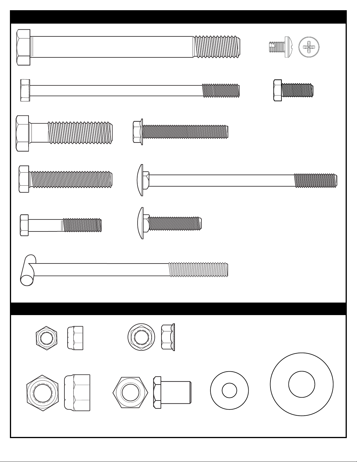
#16 (2)
#12 (1)
#45 (1)
#39 (2)
#23 (4)
#26 (4)
HARDWARE IDENTIFIER (BOLTS & SCREWS)
#20 (1)
#25 (2)
#51 (2)
#18 (6)
HARDWARE IDENTIFIER (NUTS & WASHERS)
#14 (12)
#10 (2)
#31 (10)
#48 (1)
#37 (1)
#24 (8)
#22 (6)
Page 7

12/06 ID# M682001
7
#44 (1)
#46 (1)
#47 (1)
#13 (2)
#30 (4)
#49 (1)
#50 (8)
HARDWARE IDENTIFIER (PLASTIC SPACERS CAPS & CLIPS)
HARDWARE IDENTIFIER (OTHER)
* You may have extra parts with this model.
Page 8

8
ID# M682001 12/06
7
8
8
9
13
13
Complete wheel assembly as shown in Figure A. Secure wheel bracket (7) and wheel assembly (Fig. A.)
to the tank (1) with a bolts (18) and washers (24).
24
TO INSTALL SECOND
PUSHNUT:
• Assemble Pushnut,
Wheels, Axle, And
Wheel Bracket As
Shown.
• Support Pushnut/Axle
From The End With A
Block Of Wood To
Install The Second
Pushnut Onto The
Axle.
NOTE:
Wood Block
TOOLS REQUIRED FOR THIS SECTION
SECTION A: ASSEMBLE THE BASE
This is what your system will look like when
you’ve finished this section.
9/16”, 1/2”
9/16”
1/2”
(2) Wrenches
AND/OR
(2) Socket Wrenches and Sockets
Extension
1.
Sawhorse or
support table
18
Fig. A.
7
1
18
24
Page 9

12/06 ID# M682001
9
Correctly identify each pole section. Poles have an identification sticker that will be used as a
reference point in the next step.
2.
Bounce middle pole section (5) into top section (4) using a wood scrap as shown until the top pole no
longer moves toward the pole identification sticker on the middle pole.
3.
4
5
6
BOTTOM
TOP
MIDDLE
IDENTIFICATION STICKER
5
4
Wood Scrap (not supplied)
Align dimple of top pole section (4) into trough of
middle pole section (5) as shown.
IMPORTANT!
HOLE
DIMPLE
middle pole
5”
(12.7 cm)
middle pole
1.5” (3.81 cm)
ID STICKER
Trough
THE IDENTIFICATION
STICKER IS LOCATED
5" FROM THE END OF
THE POLE. WHEN
PROPERLY POUNDED
TOGETHER, THE
POLE SECTIONS
SHOULD HAVE A 41/2" MINIMUM
OVERLAP, LEAVING
1/2" BETWEEN THE
OVERLAPPING POLE
AND THE
IDENTIFICATION
STICKER.
CAUTION!
Page 10

10
ID# M682001 12/06
4.
Bounce top and middle pole assembly (4 and 5)
onto bottom pole section (6) using a wood scrap as
shown. Bounce until the top and middle pole
assembly no longer moves toward the pole
identification mark on the bottom pole.
4
5
6
RODS SHOWN ARE FOR
VISUAL REPRESENTATION OF
ALIGNMENT AND ARE NOT
SUPPLIED WITH THE
HARDWARE
Align dimple of middle pole section (5) into
trough of bottom pole section (6) as shown.
IMPORTANT!
HOLE
DIMPLE
Bottom pole
1.5” (3.81 cm)
ID STICKER
Bottom pole
5”
(12.7 cm)
Trough
Dimple
Wood Scrap
(not supplied)
Page 11

12/06 ID# M682001
11
6.
Secure tank struts (2) through center hole in
pole as shown.
12
10
2
2
TWO CAPABLE ADULTS
REQUIRED FOR THIS
PROCEDURE. FAILURE TO
FOLLOW THIS WARNING COULD
RESULT IN SERIOUS INJURY
AND/OR PROPERTY DAMAGE.
WARNING!
IMPORTANT!
DO NOT TIGHTEN
COMPLETELY.
5.
Attach pole assembly to tank (1) as shown.
Secure pole assembly to tank using
bolts (25) and pole mounting plate (19) as
shown.
TWO CAPABLE ADULTS
REQUIRED FOR THIS
PROCEDURE. FAILURE TO
FOLLOW THIS WARNING COULD
RESULT IN SERIOUS INJURY
AND/OR PROPERTY DAMAGE.
WARNING!
6
19
1
25
24
24
Page 12

12
ID# M682001 12/06
8.
42
6
14
16
15
IMPORTANT!
DO NOT OVER
TIGHTEN!
7.
2
2
18
24
24
2
2
18
IMPORTANT!
DO NOT TIGHTEN
COMPLETELY.
TWO CAPABLE ADULTS
REQUIRED FOR THIS
PROCEDURE. FAILURE TO
FOLLOW THIS WARNING COULD
RESULT IN SERIOUS INJURY
AND/OR PROPERTY DAMAGE.
WARNING!
Rotate non-secured ends of tank struts (2) to mounting
holes in tank as shown. Secure non-secured ends of tank
struts (2) to tank as shown.
IMPORTANT!
TIGHTEN ALL HARDWARE
FROM STEPS 6-8 AFTER THIS
ASSEMBLY IS COMPLETED.
Install pole mount bracket (15) and
reinforcement bracket (42) with carriage bolts
(16) as shown. Tighten flange nuts (14)
completely.
Page 13

12/06 ID# M682001
13
Securely rest the assembly on sawhorse. Identify elevator
tubes (32 and 35).
35
32
9.
Toward Pole
Toward Board
4
35
51
50
40
49
29
29
40
50
COMPLETED ASSEMBLY
31
32
TWO CAPABLE ADULTS
REQUIRED FOR THIS
PROCEDURE. FAILURE TO
FOLLOW THIS WARNING COULD
RESULT IN SERIOUS INJURY
AND/OR PROPERTY DAMAGE.
WARNING!
TIGHTEN BOLT (29) IN
LOCK NUT (31) UNTIL
FLUSH (EVEN) WITH LOCK
NUT’S OUTER EDGE.
WARNING!
10.
While the system is securely resting on the sawhorse. Install elevator tubes (32 and 35) to top pole
section (4) as shown. Install pole cap (38) at this time.
Lower Elevator tube
32
Upper Elevator tube
35
50
38
32
31
31
50
35
Page 14

14
ID# M682001 12/06
While still supported on sawhorse. Attach elevator tubes (32, 35) to backboard using spacers (30),
bolts (23), and nuts (31) as shown.
30
1.
Sawhorse or Support Table
9/16”, 1/2”, 3/4”
9/16”
1/2”
3/4”
Extension
TOOLS REQUIRED FOR THIS SECTION
SECTION B: ATTACH THE BACKBOARD
This is what your system will look like when you’ve
finished this section.
(2) Wrenches
AND/OR
(2) Socket Wrenches and Sockets
31
Phillips Screwdriver
23
Page 15

12/06 ID# M682001
15
2.
45
Insert T-bolt (45) into Slam Jam bracket (44) then, attach that assembly to board using
bolts (26) and nuts (14).
14
26
27
IMPORTANT!
Carefully cut and
peel protective film
away from board
prior to attaching
rim.
44
44
Page 16

16
ID# M682001 12/06
3.
29
31
36
35
35
WARNING!
USE EYE PROTECTION WHEN
INSTALLING SPRINGS.
35
35
Support pole on sawhorse. Attach counter balance spring (36) to the spring support bracket (27) using bolt (51) and
nut (31) as shown.
Insert bolt (29) through left side upper elevator tube (35), then stretch spring (36) onto bolt (29). Insert
bolt (29) through right side upper elevator tube (35) and secure with nut (31).
51
31
36
27
Page 17

12/06 ID# M682001
17
Install Slam Jam Rim to Backboard
A. Fit rim (34) securely into bracket (44) as shown. Allow T-bolt (45) to slip through center
hole in rim (34).
B. Install reinforcement bracket (46) onto T-bolt (45) as shown.
C. Install spring (47) onto T-bolt (45) as shown.
D. Install special nut (48) and washer (37) onto T-bolt (45).
E. Tighten nut (48) until flush with end of T-bolt (45).
4.
46
48
37
44
45
34
47
45
37
48
A
B
C
D
E
45
45
NOTE:
ORIENTATION
OF BRACKET
46
Page 18

18
ID# M682001 12/06
Slide upper tube (17) onto handle assembly (3). Reinsert screws removed in previous step as shown.
5.
6.
Remove packaging materials from handle assemblies (17 and 3).
Remove screws on both sides of tube.
17
3
17
Screws removed in step 6
3
Rotate upper tube to line up screw holes. Reinsert
screws removed in previous step as shown.
NOTE:
Page 19

12/06 ID# M682001
19
Install handle assembly (17) to lower elevator tubes (32) using bolt (29),
spacers (50), and nut (31) as shown.
Secure the handle assembly (3 & 17) to pole bracket
(15) using bolt (20) and nut (10) as shown.
8.
Secure the front panel (21) to struts (2) as
shown with carriage bolts (22) and nuts (14).
9.
17
29
31
15
42
20
10
3
14
22
21
50
50
7.
Loosening the strutto-pole bolt (12)
can help when
aligning front cover
to struts.
Retighten bolt (12)
when front cover
attachement is
completed.
NOTE:
WARNING!
Page 20

20
ID# M682001 12/06
10.
Roll completed assembly to desired position. Fill tank with water (approx. 40 gallons (128 Liters)) or
sand (approx. 475 lbs. (216 kg)) and rotate the cap (41) into base (1).
TWO CAPABLE ADULTS
REQUIRED FOR THIS
PROCEDURE. FAILURE TO
FOLLOW THIS WARNING
COULD RESULT IN SERIOUS
INJURY AND/OR PROPERTY
DAMAGE.
ADD TWO GALLONS (7.6
LITERS) OF NON-TOXIC
ANTIFREEZE IN SUBFREEZING CLIMATES.
IF USING SAND
: 2 GALLONS
OF ANTI-FREEZE IS NOT
REQUIRED.
CAUTION!
SAND
SAND
(475 lb.)
(475 lb.)
(216 kg)
(216 kg)
WARNING!
DO NOT LEAVE ASSEMBLY
UNATTENDED WHEN EMPTY;
IT MAY TIP OVER.
Cap (41) MUST be tightened COMPLETELY and
SECURELY to prevent leakage.
CHECK WATER LEVEL BEFORE EACH USE!
FAILURE TO FOLLOW THIS WARNING COULD
RESULT IN SERIOUS INJURY AND/OR
PROPERTY DAMAGE.
WARNING!
1
41
Page 21

12/06 ID# M682001
21
Apply Height Adjustment and Moving Label (33) to front of
pole, where it is clearly visible.
11.
12.
B.
D.
C.
A.
Install net (43).
34
39
28
Cover plate (28) will fit
INSIDE back bracket.
NOTE:
43
34
43
34
13.
RIM COVER ATTACHMENT
39
56620012/05
T
ADJUS
G
M
Adj
d
heigh
to
lowest
.
W
g
p
otate
basketba
d
unt
s
engage
th
.
M
ll
s
desired
.
C
ll
.
2
3
5
C
bility
33
EIGH
TO ADJUST BACKBOARD:
1. Grasp handle and press button.
2. Raise or lower to desired height.
3. Release button.
TMENT
VIN
1
2
3
4
YSTE
ustbasketball backboar
t
hileholdin
.
.
.
ll system forwar
il wheel
ground
ovebasketba
location
arefully rotate basketba
system upright
heck system for sta
position
ole, r
wi
ystem to
.
Page 22

22
ID# M682001 12/06
SECTION C: BOARD PAD
Item Qty. Part No. Description
1 1 20157801 Board Pad, Left Section
2 1 20157901 Board Pad, Right Section
3 1 201580 Board Pad, Center Section
4 4 206081 Screw, Self Drilling, Hex Washer Head, 1/4 x .75” Long
5 6 202219 Cap, Screw
6 1 205355 Drill Bit, 11/64
7 2 201596 Screw, Lag, Hex Washer Head, 1/4 x 1.25” Long
HARDWARE IDENTIFIER
PARTS LIST - See Hardware Identifier
#4 (4)
#7 (2)
#6 (8)
#5 (8)
#1 (1) #2 (1) #3 (1)
ITEMS REQUIRED FOR THIS SECTION
Flat-Head Screwdriver
Socket Wrenches and Sockets
OR
3/8”
Portable Drill with Torque Adjustment
Page 23

12/06 ID# M682001
23
Using a portable drill (with adjustable torque) and a
5/16 socket and extension drill through the
backboard frame and secure the pads in place with
self-tapping screws provided. Use screws (7) for
center pad and screws (4) for outer pads
It may be necessary to use an 11/16 drill bit (6) to
pre-drill on some backboards (FIG. A).
A center punch is recommended to mark hole
locations prior to drilling to keep drill bit from
wandering.
If the ends of the screws are exposed after
installation, place the screw protectors (5) over the
ends to prevent injury.
BOARD PAD - INSTALLATION
1.
Check the fit of the edge guards and reposition
slightly if necessary. It may be necessary to trim
away some material to fit it around the goal or
supports. NOTE: CHECK FASTENER LOCATIONS
TO MAKE SURE THEY WILL NOT DAMAGE THE
BACKBOARD GLASS.
1
2
7
4
4
3
5
4
4 or 7
FIG. A.
6
The enclosed Molded Edge Guards interlock together to form bottom and side protection for
one backboard with an overall width of 54".
3.
2.
Collect any metal shavings that may have fallen
onto the floor or driveway to prevent injury.
 Loading...