

Page 1
H
U
F
F
Y
HUFFY
SPOR
TS
REQUIRED TOOLS
SAND
450 LBS
.
(204 KG)
AND MATERIALS:
• 2 People
Por table System
• Tape Measure
• Wood Board (scrap)
• Sawhorse or Support
Table
• Hammer
• Tape
• Safety Glasses
• Phillips Screwdriver
• Scissors
• (2 each) Wrenches and/or
Socket Wrenches and Sockets
(Deep-Well Sockets are
Recommended).
3/8" 1/2" 9/16" 3/4"
AND/OR
Owners Manual
Customer Service Center
• N53 W24700 South Corporate Circle • Sussex, WI 53089 • U.S.A.
3/8" 1/2" 9/16" 3/4"
• Extension is Recommended.
• Garden Hose or Sand
SAND
SAND
(360 lb.)
(360 lb.)
(163 kg)
(163 kg)
• Step Ladder - 8 ft. (2.4 m)
OPTIONAL TOOLS
AND MATERIALS:
• Large & Small Adjustable
Wrenches
WARNING!
READ AND UNDERSTAND
OPERATOR'S MANUAL
BEFORE USING THIS UNIT.
FAILURE TO FOLLOW
OPERATING INSTRUCTIONS
COULD RESULT IN INJURY
OR DAMAGE TO
PROPERTY.
Write Model Number
From Box Here:
Toll-Free Customer Service Number for U.S: 1-800-558-5234,
For Canada: 1-800-284-8339,
For Europe: 00 800 555 85234 (Sweden: 009 555 85234),
For Australia: 1-800-632 7921
Internet Address: http://www.huffysports.com
© COPYRIGHT 2005 by SPALDING
1
08/05 ID# M601114
Page 2
10-3/4" High
4" Wide
PMS 021 for Warning
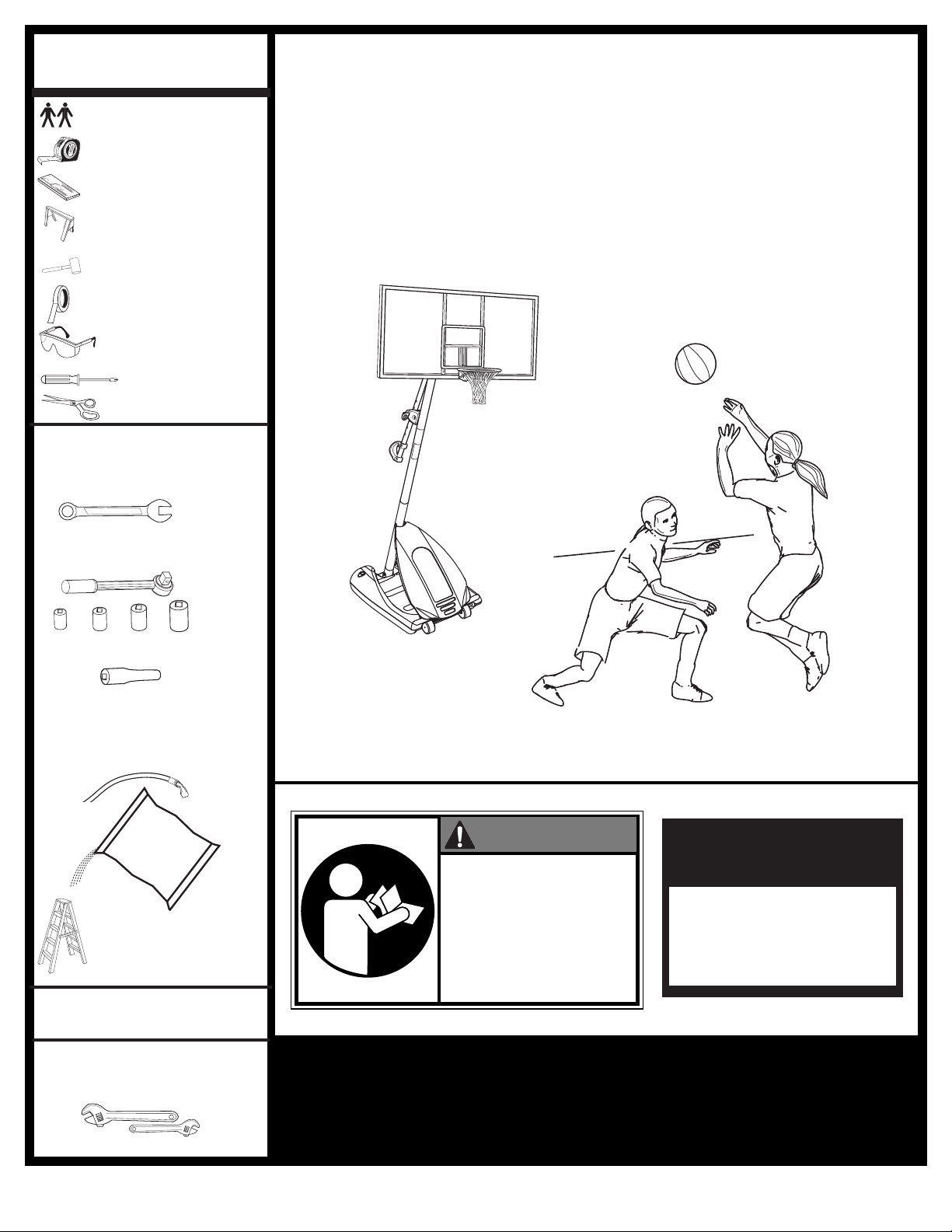
Owner must ensure that all players know and follow these rules
for safe operation of the system.
WARNING
•
DO NOT HANG on the rim or any part of the system including
backboard, support braces or net.
•
During play, especially when performing dunk type activities,
keep player's face away from the backboard, rim and net.
Serious injury could occur if teeth/face come in contact with
backboard, rim or net.
•
Do not slide, climb, shake or play on base and/or pole.
•
After assembly is complete, fill system completely with water
or sand. Never leave system in an upright position without
filling base with weight, as system may tip over causing
injuries.
•
When adjusting height or moving system, keep hands and
fingers away from moving parts.
•
Do not allow children to move or adjust system.
•
During play, do not wear jewelry (rings, watches, necklaces,
etc.). Objects may entangle in net.
•
Surface beneath the base must be smooth and free of gravel or
other sharp objects. Punctures cause leakage and could cause
system to tip over.
•
Keep organic material away from pole base. Grass, litter, etc.
could cause corrosion and/or deterioration.
•
Check pole system for signs of corrosion (rust, pitting,
chipping) and repaint with exterior enamel paint. If rust has
penetrated through the steel anywhere, replace pole
immediately.
•
Check system before each use for proper ballast, loose
hardware, excessive wear and signs of corrosion and repair
before use.
•
Check system before each use for instability.
•
Do not use system during windy and/or severe weather
conditions; system may tip over. Place system in the storage
position and/or in an area protected from the wind and free
from personal property and/or overhead wires.
•
Never play on damaged equipment.
•
When moving system, use caution to keep mechanism from
shifting.
•
Keep pole top covered with cap at all times.
•
Do not allow water in tank to freeze. During sub-freezing
weather add 2 gallons of non-toxic antifreeze, sand or empty
tank completely and store. (Do not use salt.)
•
While moving system, do not allow anyone to stand or sit on
base or have added ballasting on base.
•
Do not leave system unsupervised or play on system when
wheels are engaged for moving.
•
Use Caution when moving system across uneven surfaces.
System may tip over.
•
Use extreme caution if placing system on sloped surface.
System may tip over more easily.
•
See instruction manual for proper installation and
maintenance.
Read and understand warnings listed
below before using this product.
Failure to follow these warnings may
result in serious injury and/or property
damage.
ID#: 556790 05/05
MUNSELL NOTATION
Hue Value Chroma
5.0 YR 6.0/15
Equiv. CIE Data
(Y%) x y
30.05 0.5510 0.4214
Approx. PMS Color
13 parts yellow
3 parts Warm Red
1/4 part Black
Warning Area = Orange
Size = 4" x 6.5"
Corner Radius = 3/8"
Die Cut Label
3.25 Mil Vinyl
All Temp. Permanent Adhesive
1 Mil. Polypropolyne Overlaminate
Illustrator 8.0 = EPS
Backing + 1/16 Circumference
Rolls of 500
In the U.S.: 1-888-713-5488
In the U.S.: 1-800-558-5234
Canada: 1-800-284-8339
In the U.S.: 1-800-334-9111
In the U.S.: 1-800-772-5346
BEFORE YOU START!
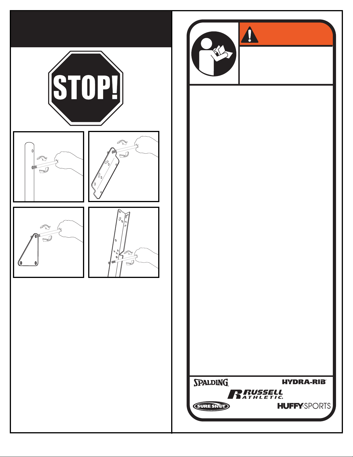
o ensure optimal playability of backboard system, a
T
close tolerance fit between the elevator components
and hardware is required. Test-fit large bolts into large
holes of elevator tubes, backboard brackets, and
motion to ream out any excess paint from holes if
Not all items pictured are included with every model.
triangle plates. Carefully rock them in a circular
necessary
.
ID# M601114 8/05
2
Page 3
SAFETY INSTRUCTIONS
Size = 4" x 5.5"
Corner Radius = 3/8"
Die Cut Label
3.25 Mil Vinyl
All Temp. Permanent Adhesive
1 Mil. Polypropolyne Overlaminate
Illustrator 8.0 = EPS
Backing + 1/16 Circumference
Rolls of 500
2
2
1
3
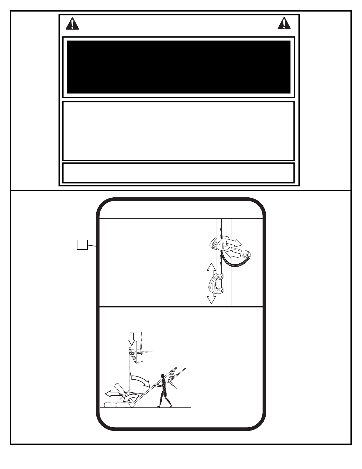
TO ADJUST BACKBOARD:
1. While holding handle, remove pin.
2. Move elevator up or down to
desired height.
3. Replace pin full length to lock
system at desired height.
511679 05/05
1
2
4
3
MOVING SYSTEM
Adjust basketball backboard
height to lowest position.
While holding pole, rotate
basketball system forward
until wheels engage with
ground.
Move basketball system to
desired location.
Carefully rotate basketball
system upright.
1.
2.
3.
4.
5.
Check system for stability.
HEIGHT ADJUSTMENT
FAILURE TO FOLLOW THESE SAFETY INSTRUCTIONS MAY RESULT IN SERIOUS INJURY,
PROPERTY DAMAGE AND WILL VOID WARRANTY.
Owner must ensure that all players know and follow these rules for safe operation of the system.
To ensure safety, do not attempt to assemble this system without following the instructions carefully. Proper
and complete assembly, use and supervision is essential for proper operation and to reduce the risk of
accident or injury. A high probability of serious injury exists if this system is not installed, maintained, and
operated properly.
• If using a ladder during assembly, use extreme caution.
• Check base regularly for leakage. Slow leaks could cause the system to tip over
unexpectedly
• Seat the pole sections properly (if applicable). Failure to do so could allow the pole
sections to separate during play and/or during transport of the system.
• Climate, corrosion or misuse could result in system failure.
• If technical assistance is required, contact Huffy Sports.
• Minimum operational height is 6’6” (1.98m) to the bottom of backboard.
Most injuries are caused by misuse and/or not following instructions.
Use caution when using this unit.
42
3
08/05 ID# M601114
Page 4
NOTICE TO ASSEMBLERS
ALL Huffy Sports Basketball Systems, including those used for DISPLAYS, MUST be assembled
and ballasted with sand or water according to the instructions. Failure to follow instructions
could result in SERIOUS INJURY. It is NOT acceptable to devise a makeshift weight system.
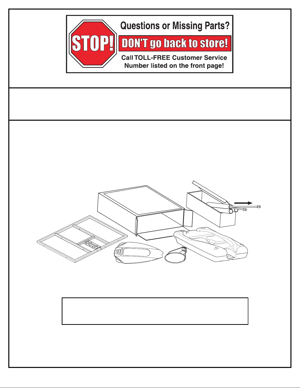
IMPORTANT!
Remove all contents from boxes.
Be sure to check inside pole sections;
hardware and additional parts are packed inside.
WARRANTY CARD:
Please remember to complete your product registration form either on-line at:
www.huffysports.com/customer_support/product_registration
or mail-in the enclosed postcard.
ID# M601114 8/05
4
Page 5
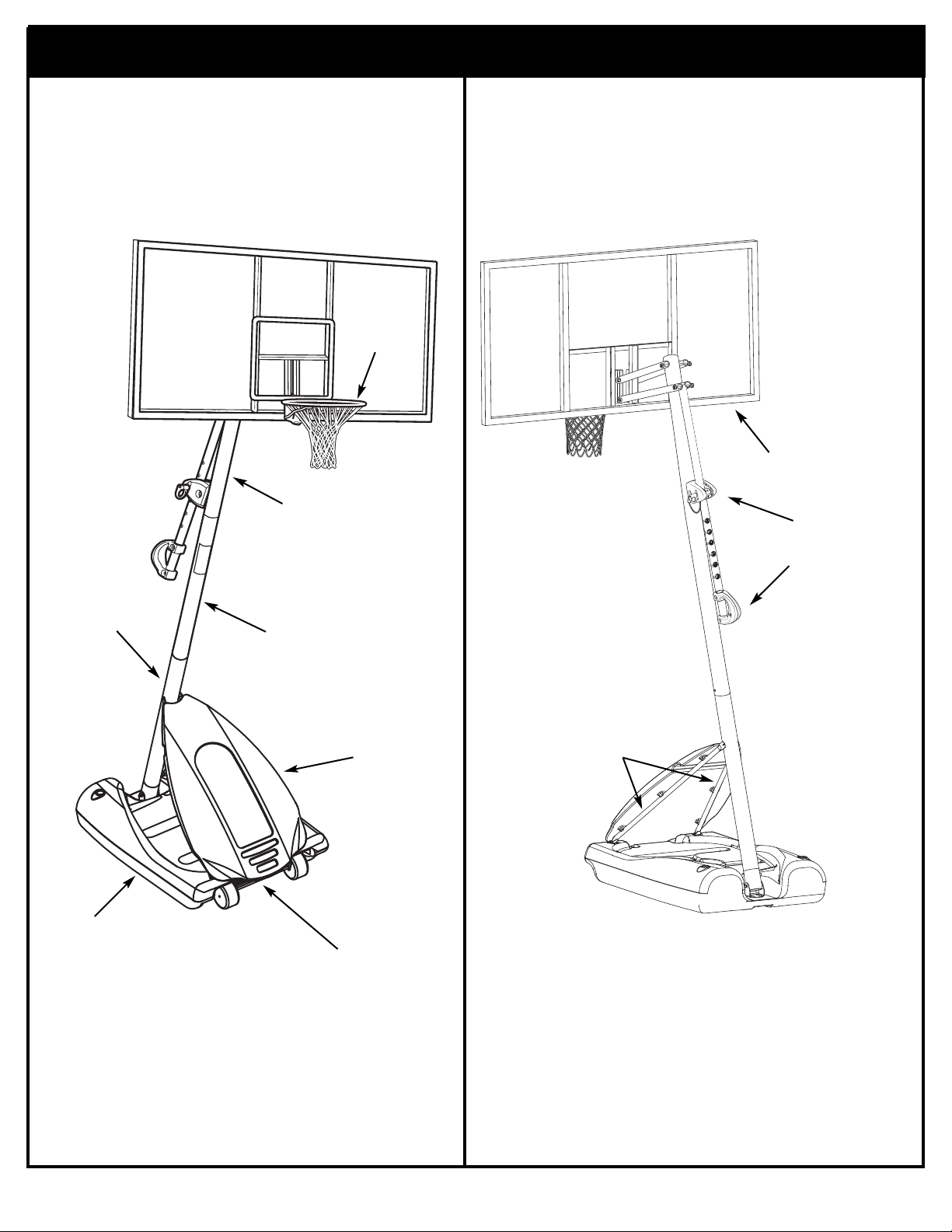
Get to know the basic parts of your basketball system...
FRONT
TOP POLE
BACK
RIM
BACKBOARD
ELEVATOR
ASSEMBLY
BOTTOM
POLE
BASE
MIDDLE
POLE
COVER
WHEEL
CARRIAGE
ASSEMBLY
FRONT
STRUTS
5
08/05 ID# M601114
Page 6
PARTS LIST - See Hardware Identifier
Item Qty. Part No. Description
1 1 908026 Top Pole Section
2 1 90810701 Middle Pole Section (with Label
3 1 908015 Bottom Pole Section
4 1 900223 Wheel Bracket
1 206940 Axle
5
6 2 226403 Wheel
7 2 206938 Pushnut
8 1 206660 Base
9 6 203156 Hex Bolt, 5/16-18 x 1
10 18* 203218 Flat Washer, 5/16
11 15* 203100 Hex-Flange Nut, 5/16-18
12 1 201581 Pole Bracket
13 2 202662 Hex Bolt, 5/16-18 x 4.5
14 2 203099 Lock Nut, 5/16-18
15 4 203223 Carriage Bolt, 5/16-18 x 1
16 2 906410 Tank Strut
17 1 200516 Bolt Cover
18 1 206990 Reinforcement Bracket
19 3 203038 Carriage Bolt, 5/16-18 x 2-3/4 Long
20 8 202862 Spacer, Plastic, 1.19" Long
21 7 206340 Lock Nut, 1/2-13
22 2 203053 Carriage Bolt, 5/16-18 x 4 Long
23 1 204872 Label, Height Indicator
24 2 204858 Spacer, Plastic, Biscuit
25 1 207103 Pole Cap
26 1 204853 Lanyard, Black Coil
27 1 204850 Pin, Locking
28 1 204832 Bracket, Pole Mount
29 4 206360 Hex Bolt, 3/8-16 x 2.625
30 6 203063 Nylon Insert Lock Nut, 3/8-16
31 4 201124 Lock Nut, 3/8-16
32 2 900867 Plate, Triangle
33 2 904807 Elevator Tube, Upper - Short
34 2 900183 Elevator Tube, Lower - Long
35 2 204859 Cover, Pin Slide
Item Qty. Part No. Description
36 2 204838 Spring, Counter Balance
37 2 203617 Base Plug
38 1 201965 Front Cover
39 4* 203257 Tie Straps
0 1 200504 Rim Cover
4
41 2 200520 Screw, #8 x .75
42 1 511679 Label, Height Adj and Moving
43 2 204857 Spacer, Metal 1/2” O.D. x 1.44 Long
44 1 205226 Left Board Pad
45 1 205225 Right Board Pad
46 6* 201596 Sheet Metal Screw, #14 x 1.25
47 6* 206303 Flat Washer, 1/4
48 1 205241 Center Board Pad
49 1 202856 Bolt, Hex, 1/2-13 x 4" Long
50 4 203232 Flat Washer, 3/8
51 1 202795 Label, NBA
52 2 90096401 Bracket, Backboard Support
53 4 201681 Spacer, Plastic, .530 I.D. x .88 Long
54 2 203103 Carriage Bolt, 5/16-18 x 2 Long
55 1 204803 Screw, Phillips Head
56 4 201682 Spacer, .530 I.D. x 1.875
57 6 202532 Bolt, Hex, 1/2-13 x 9.5"
58 1 904866 Height Adjustment Rod
59 1 204855 Handle, Left
60 1 204856 Handle, Right
61 1 900033 Bracket, Slam Jam
62 1 200318 Bracket, Reinforcement, Slam Jam
63 1 203470 Washer Flat, Slam Jam
64 1 203472 Spring, Black, Slam Jam
65 1 203795 Nut, Special, Slam Jam
66 1 203796 T-Bolt, 3/8-16 x 5 Long
67 Rim
68 4 205528 Bolt, Hex Flange, 5/16-18 x 1 Long
68 1 Net
*You may have extra parts with this model.
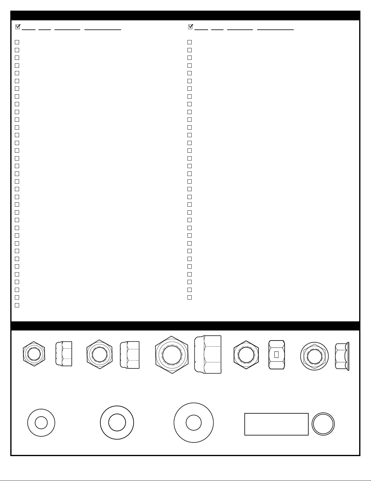
HARDWARE IDENTIFIER (NUTS, WASHERS & METAL SPACERS)
Item #14 (2)
Item #30 (4)
Item #47 (6)*
ID# M601114 8/05
Item #50 (4)
Item #21 (7)
Item #10 (18)*
6
Item #31 (4)
Item #43 (2)
Item #11 (15)*
Page 7
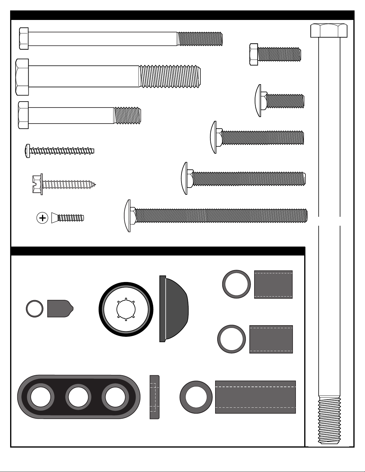
Item #29 (4)
Item #55 (1)
HARDWARE IDENTIFIER (BOLTS & SCREWS)
Item #13 (2)
Item #9 (6)
Item #49 (1)
Item #15 (4)
Item #54 (2)
Item #46 (6)
Item #41 (2)
HARDWARE IDENTIFIER (PLASTIC SPACERS & CAPS)
Item #17 (1)
Item #19 (1)
Item #57 (6)
Item #22 (2)
Item #53 (4)
Item #7 (2)
Item #20 (8)
Item #24 (2)
Item #56 (4)
7
08/05 ID# M601114
Page 8
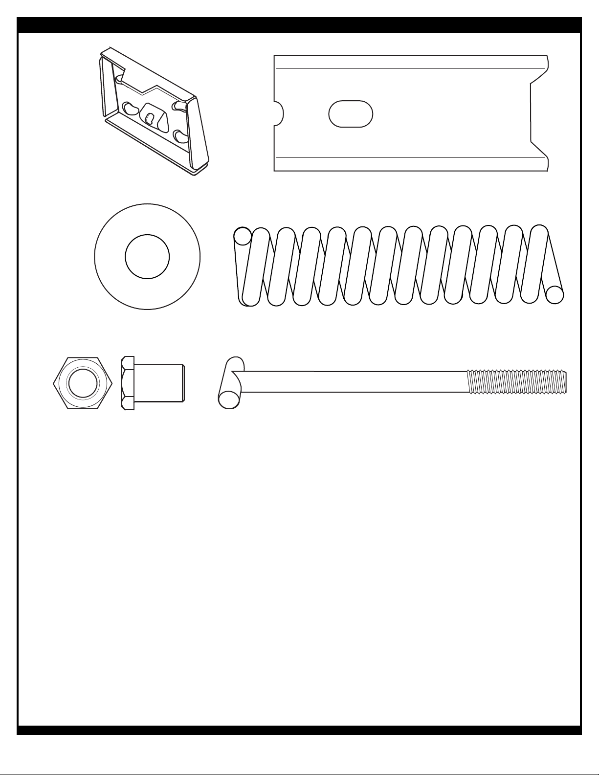
HARDWARE IDENTIFIER (OTHER)
Item #61 (1)
Item #63 (1)
Item #65 (1)
Item #62 (1)
Item #64 (1)
Item #66 (1)
ID# M601114 8/05
8
Page 9
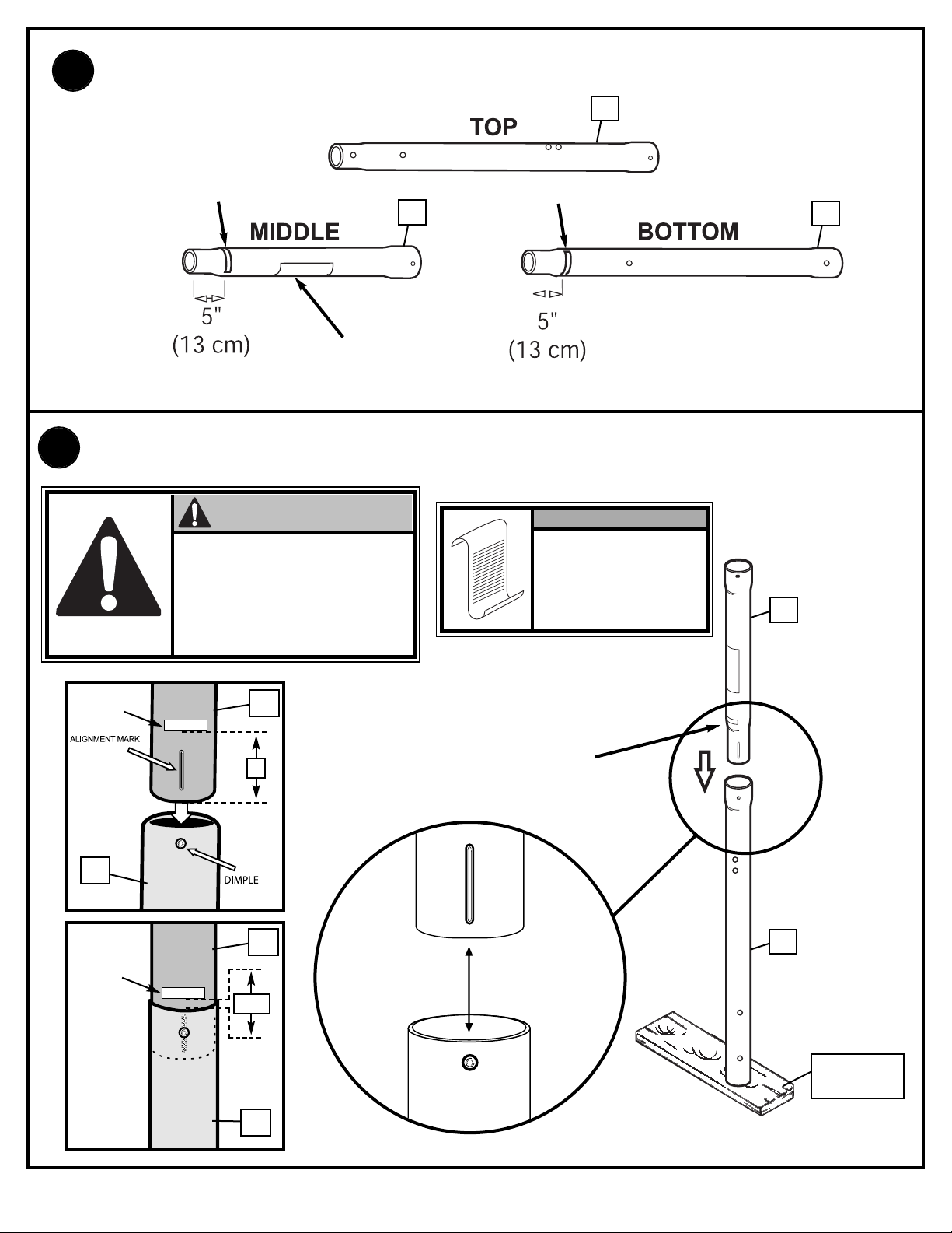
1.
Correctly identify each pole section.
1
I.D. Label
I.D. Label
2
WARNING
LABEL
Bounce middle pole (2) into top pole section (1) using a wood scrap as shown until top
2.
pole no longer moves toward pole identification mark on middle pole.
CAUTION!
THE IDENTIFICATION STICKER IS
LOCATED 5" FROM THE END OF THE
POLE. WHEN PROPERLY POUNDED
TOGETHER, THE POLE SECTIONS
SHOULD HAVE A 3-1/2" MINIMUM
OVERLAP, LEAVING 1-1/2" BETWEEN
THE OVERLAPPING POLE AND THE
IDENTIFICATION STICKER.
NOTE:
POLE SECTIONS
SHOULD HAVE A
3-1/2" (9 CM)
MINIMUM
OVERLAP.
3
2
IDENTIFICATION
STICKER
1
IDENTIFICATION
STICKER
middle pole
middle pole
5"
1-1/2"
1
2
POLE
IDENTIFICATION
MARK
2
1
WOOD SCRAP
(NOT SUPPLIED)
9
08/05 ID# M601114
Page 10
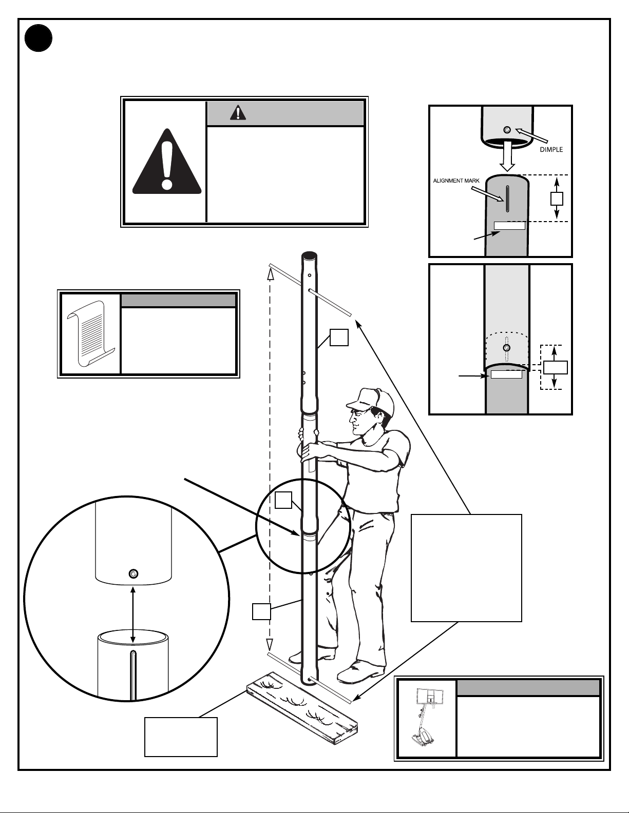
Align dimple of middle pole with slot of bottom pole.While maintaining alignment, bounce
3.
top and middle pole assembly (1 & 2) onto lower pole section (3) as shown until they no
longer move toward pole identification mark.
CAUTION!
THE IDENTIFICATION STICKER IS
LOCATED 5" FROM THE END OF
THE POLE. WHEN PROPERLY
POUNDED TOGETHER, THE POLE
SECTIONS SHOULD HAVE A 3-1/2"
MINIMUM OVERLAP, LEAVING 1-1/2"
BETWEEN THE OVERLAPPING
POLE AND THE IDENTIFICATION
STICKER.
NOTE:
POLE SECTIONS
SHOULD HAVE A
3-1/2" (9 CM)
MINIMUM
OVERLAP.
IDENTIFICATION
STICKER
1
IDENTIFICATION
STICKER
ottom Pole
B
Bottom Pole
5"
1-1/2"
POLE
IDENTIFICATION
MARK
WOOD SCRAP
(NOT SUPPLIED)
2
RODS SHOWN ARE
FOR VISUAL
REPRESENTATION
OF ALIGNMENT
AND ARE NOT
SUPPLIED WITH
3
THE HARDWARE
IMPORTANT!
Holes in top (1) and bottom (3)
pole sections MUST align to
correctly position elevator
system toward playing
surface.
ID# M601114 8/05
10
Page 11
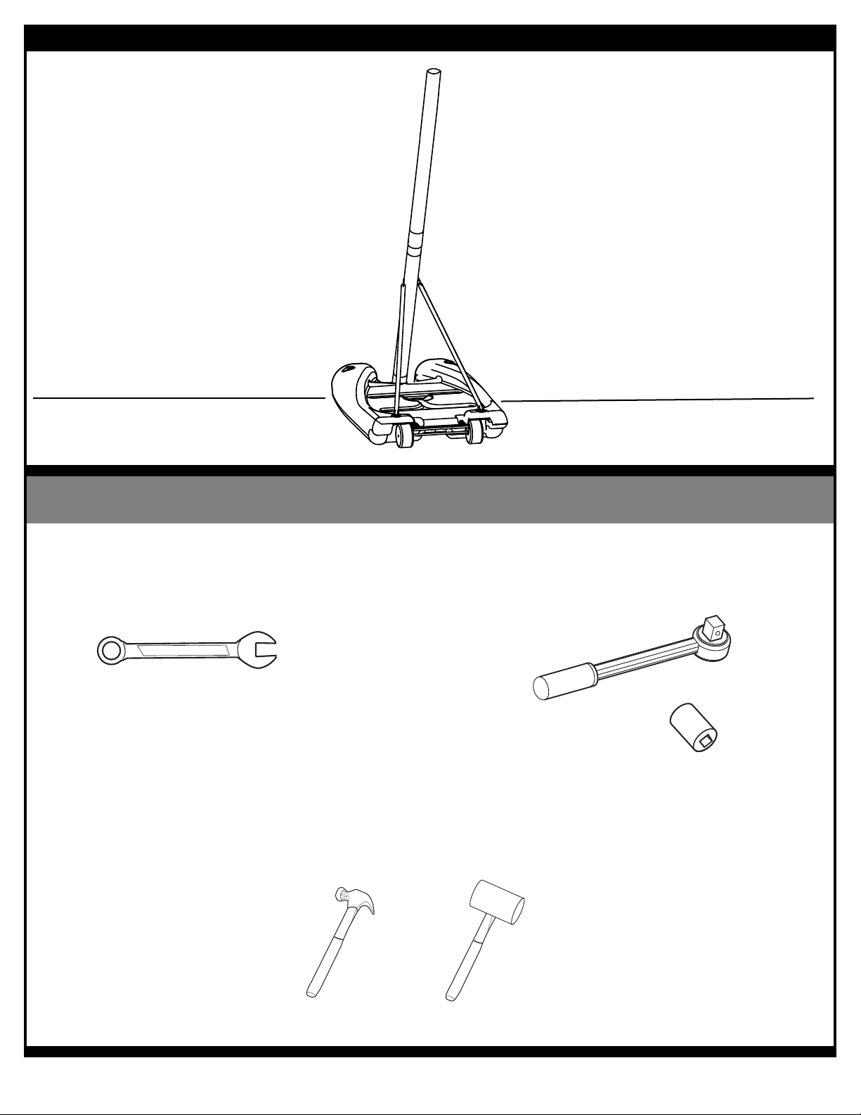
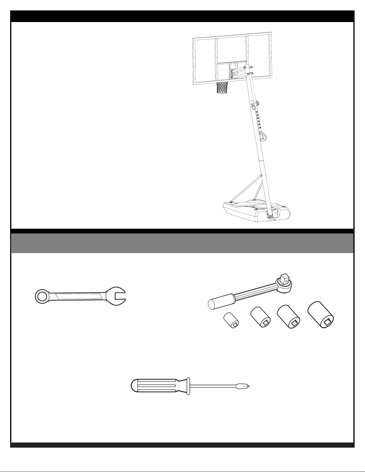
SECTION B: ASSEMBLE THE BASE
This is what your system will look like
when you’ve finished this section:
(2) 1/2”
TOOLS REQUIRED FOR THIS SECTION
(2)
AND/OR
1/2”
11
08/05 ID# M601114
Page 12
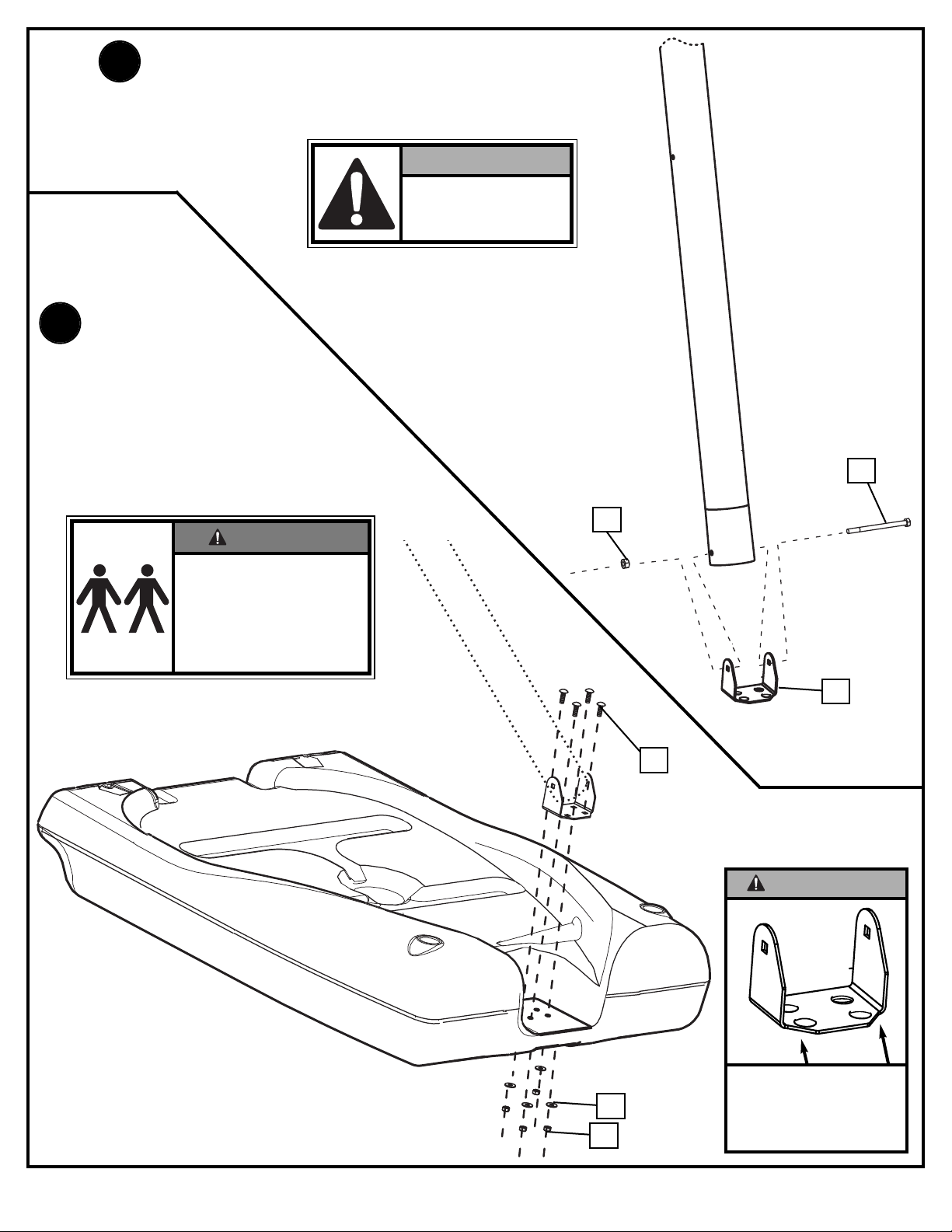
1.
Assemble pole bracket (12) using bolt (13) and
Lock Nut (14) as shown.
2.
Attach pole assembly to base
using carriage bolts (15)
washers(10) and nuts (11) as
shown. Two people are required
for this step.
IMPORTANT!
DO NOT OVER
TIGHTEN
13
WARNING!
TWO PEOPLE REQUIRED
FOR THIS PROCEDURE.
FAILURE TO FOLLOW THIS
WARNING COULD RESULT
IN SERIOUS INJURY AND/OR
PROPERTY DAMAGE.
14
12
15
IMPORTANT!
ID# M601114 8/05
12
11
10
THE CUT CORNERS OF
THE POLE BRACKET
NEED TO FACE TOWARD
THE BACK OF THE BASE
AS SHOWN.
Page 13
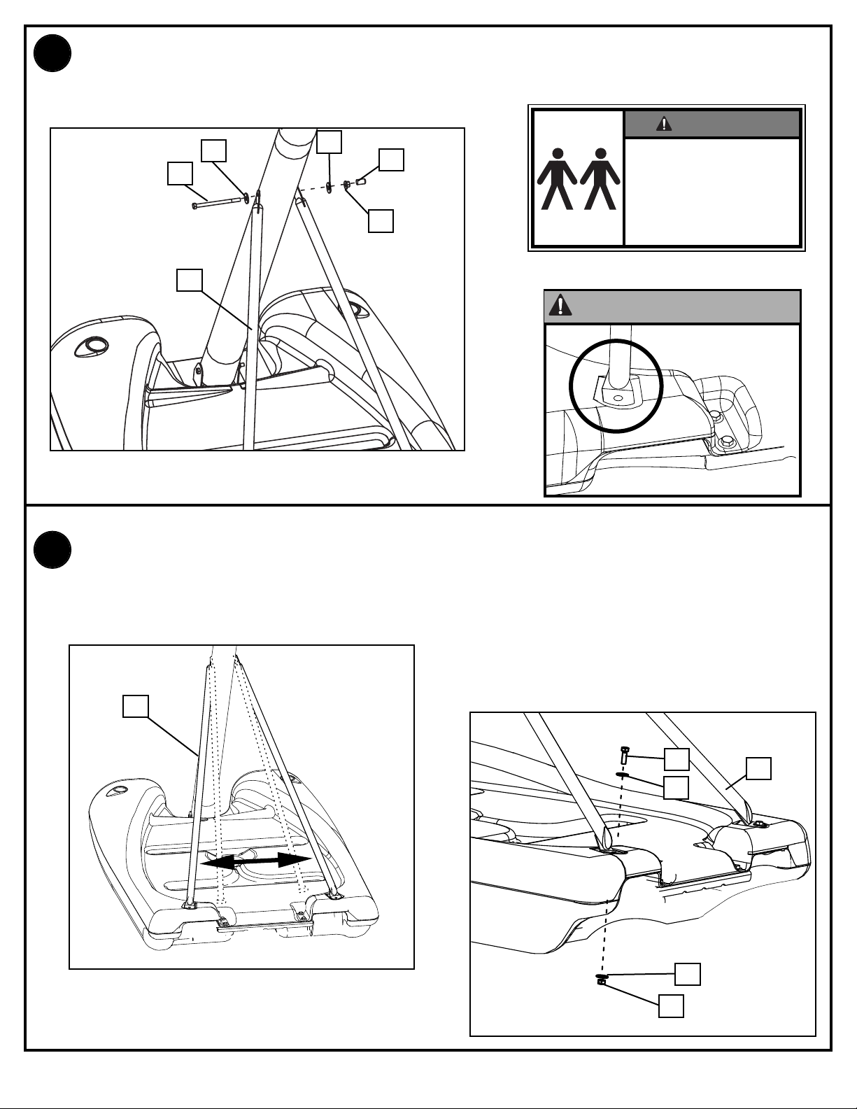
Secure tank struts (16) to pole as shown.
3.
Nut should be tightened until flush (even) with lock nuts outer edge. Place cap (17) over
exposed end of bolt as shown.
WARNING!
10
13
16
10
14
17
TWO PEOPLE REQUIRED
FOR THIS PROCEDURE.
FAILURE TO FOLLOW THIS
WARNING COULD RESULT
IN SERIOUS INJURY AND/OR
PROPERTY DAMAGE.
IMPORTANT!
Rotate non-secured ends of tank struts (16) outward to mounting holes in tank as
4.
shown.Secure ends of tank struts (16) to tank as shown. Repeat for opposite side.
16
10
9
16
13
10
11
08/05 ID# M601114
Page 14
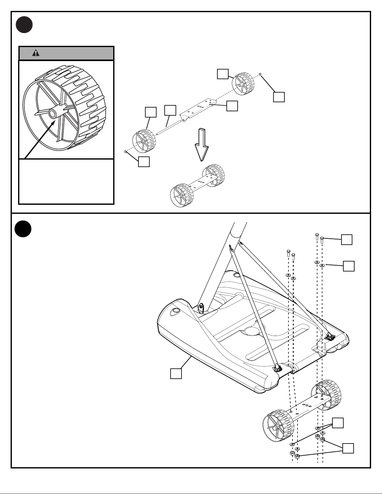
Insert axle (5) through wheel bracket (4). Secure wheels (6) to axle using pushnuts (7).
5.
Carefully tap pushnuts onto axle with hammer or mallet
IMPORTANT!
6
7
4
SIDE OF WHEEL WITH
LONGER PLASTIC AXLE
NEEDS TO FACE THE
WHEEL BRACKET.
6
7
5
Install wheel assembly to base (8) using bolts(9),
6.
washers(10) and nuts (11) as shown.
8
9
10
ID# M601114 8/05
14
10
1
1
Page 15
SECTION C: ASSEMBLE THE ELEVATOR & BACKBOARD
This is what your system will look like
when you’ve finished this section:
TOOLS REQUIRED FOR THIS SECTION
(1) 3/8”, (2) 1/2”, (2) 9/16” and
(2) 3/4”
AND/OR
3/8”
(2)
1/2”
9/16”
3/4”
15
08/05 ID# M601114
Page 16
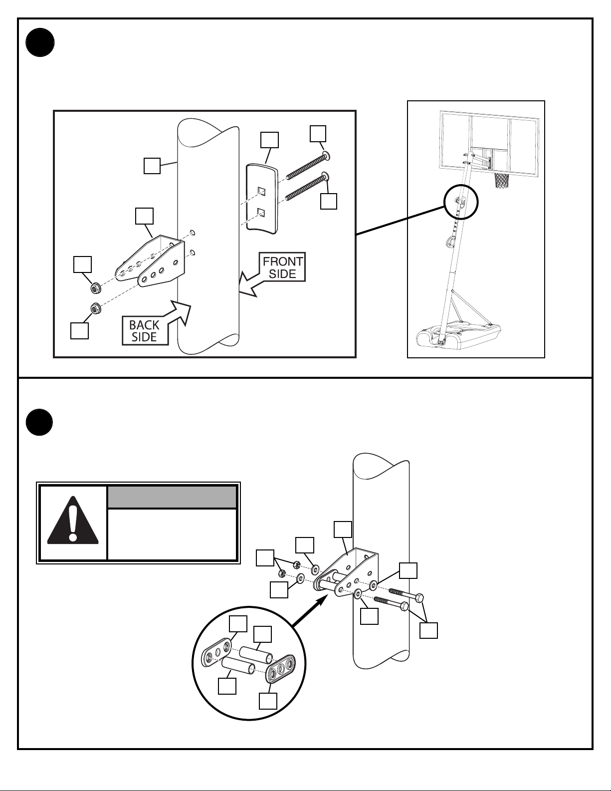
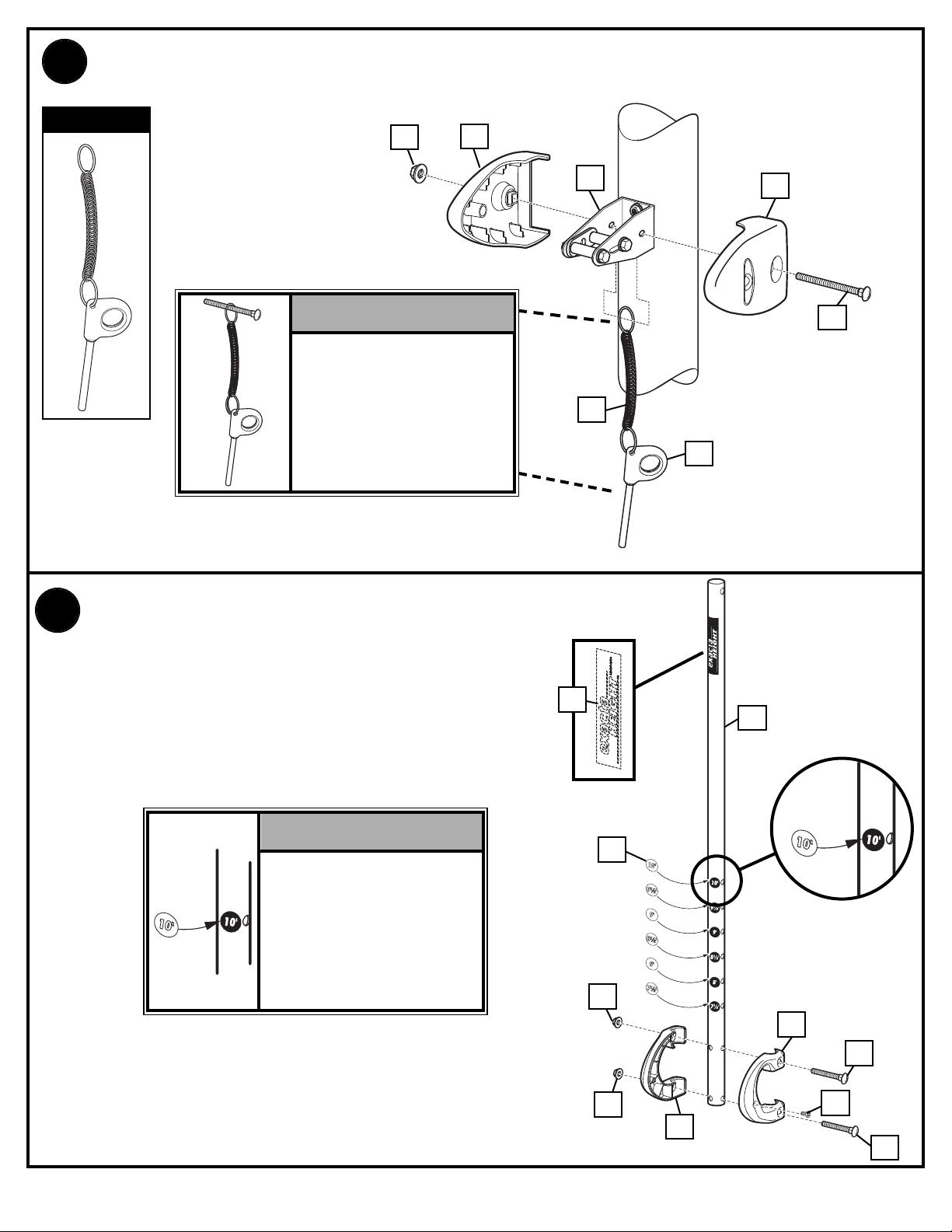
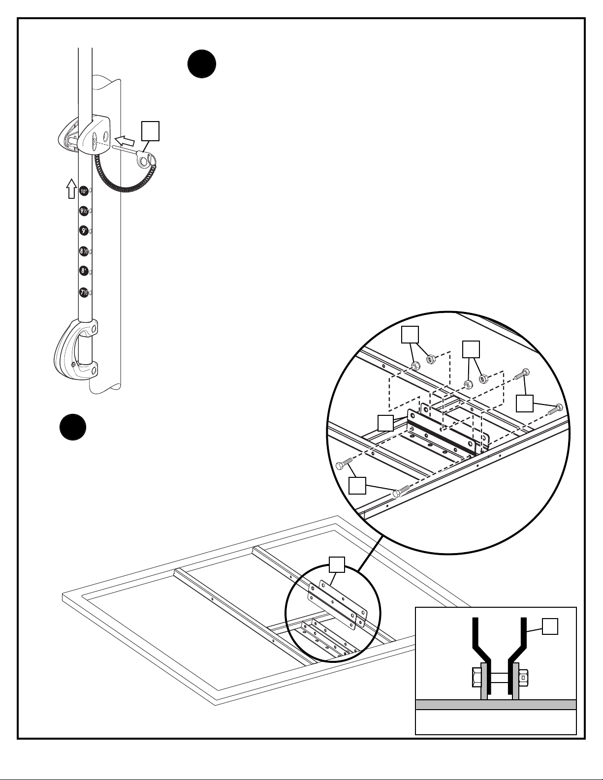
Install pole mount bracket (28) and reinforcement bracket (18) with carriage bolts (22) as
1.
shown. Tighten flange nuts (11) completely.
18
1
28
11
11
Attach spacers (24, 43) to pole mount bracket (28) with bolts (29), washers (50), and lock
2.
22
22
nuts (31) as shown.
IMPORTANT!
Tighten just until
washers (50) stop
moving.
ID# M601114 8/05
43
24
31
43
28
50
50
50
50
29
24
16
Page 17
Assemble lanyard (26) to locking pin (27) as shown (FIG A). Attach covers (35) onto pole
3.
mount bracket (28) with carriage bolt (19) and nut (11) as shown.
FIG. A
11
35
IMPORTANT!
Loop end of pin
lanyard (26) over
carriage bolt (19) as it
passes through the
pole mount bracket (28)
during this assembly.
Apply logo and height indicator labels (23) to
4.
adjustment rod (58) as shown. Attach handle parts
(59, 60) to adjustment rod with screw (55), carriage
bolts (54), and flange nuts (11) as shown.
23
28
26
35
19
27
58
IMPORTANT!
Indicator labels should
be applied as close to
holes as possible to
prevent labels from
being damaged during
height adjustment.
17
11
23
11
60
54
55
59
54
08/05 ID# M601114
Page 18
27
Insert handle assembly through pole mount assembly as
5.
shown. Lock pole assembly in place at the 10’ (3.05 m)
mark with pin (27).
30
30
6.
Assemble backboard brackets (52)
using bolts (29), and nuts (30) as
shown.
29
52
29
52
52
ID# M601114 8/05
18
NOTE
ORIENTATION
Page 19

Identify elevator tubes (33 & 34).
8.
Toward
Board
Toward
Board
Upper Elevator tube
Lower Elevator tube
33
34
Toward
Pole
Toward
Pole
Attach lower elevator tubes (34) and counter balance spring (36) to backboard support
brackets (52) using spacers (53 & 56), bolt (57), and nut (21) as shown.
53
57
56
34
36
52
56
52
36
21
34
66
52
19
68
08/05 ID# M601114
Page 20

Attach upper elevator tubes (33) to backboard support brackets (52) using spacers
9.
(53), bolt (57), and nut (21) as shown.
IMPORTANT!
Tighten ALL Hardware
from Steps 6-8 After this
Assembly is Completed.
53
56
57
56
21
52
33
53
21
56
33
56
57
ID# M601114 8/05
33
33
20
Page 21

10.
Support pole on sawhorse. Attach backboard assembly to top pole section (4) as
shown. Install pole cap (25).
21
11.
1
20
21
32
32
20
49
57
34
25
34
Install upper elevator tubes (33) to triangle plates (63) as shown. Install handle assembly
to lower elevator tubes (34) using bolt (57), spacers (20), and nut (21) as shown.
58
1
NOTE:
Before going on to
next step, set
adjustable system
assembly to the
10’ (3.05 m) setting.
20
57
20
34
57
21
21
33
20
34
32
34
20
33
21
08/05 ID# M601114
Page 22

12.
A. Fit rim (67) securely into bracket (61) as shown. Allow T-bolt (66) to slip through center hole
in rim (67).
B. Install reinforcement bracket (62) onto T-bolt (66) as shown.
C. Install spring (64) onto T-bolt (66) as shown.
D. Install special nut (65) and washer (63) onto T-bolt (66).
E. Tighten special nut (65) until flush with end of T-bolt (66).
Install Rim to Backboard
A.
67
C.
64
66
61
B.
D.
63
62
65
NOTE:
ORIENTATION
OF BRACKET
66
62
66
ID# M601114 8/05
E.
66
65
63
22
Page 23

13.
Install net (43).
A.
14.
B.
C.
D.
Insert bolt (57) through left side upper elevator tube (33), then stretch spring (36) onto
bolt (57). Insert bolt (57) through right side upper elevator tube (33) and secure with
nut (21).
WARNING!
USE EYE PROTECTION
WHEN INSTALLING
SPRINGS.
NOTE:
Peel protective
film from surface
of acrylic
backboard prior
to use.
57
36
36
33
21
33
58
23
08/05 ID# M601114
Page 24

15.
SAND
450 LBS
.
(204 KG)
FILL BASE
Roll assembly to desired playing area. Fill
base (8) with water (approx. 40 gallons) and
snap base plugs (37) in place.
WARNING!
TWO PEOPLE REQUIRED FOR
THIS PROCEDURE. FAILURE
TO FOLLOW THIS WARNING
COULD RESULT IN SERIOUS
INJURY AND/OR PROPERTY
DAMAGE.
WARNING!
DO NOT LEAVE ASSEMBLY
UNATTENDED WHEN EMPTY; IT
MAY TIP OVER.
CAUTION
ADD TWO GALLONS (7.6
LITERS) OF NON-T
OXIC
ANTIFREEZE IN
SUB-FREEZING CLIMATES.
NOTE
Sable
Sable
Sand
Sand
Arena
Arena
(163 kg)
(163 kg)
IF USING SAND: 2 GALLONS
OF ANTI-FREEZE IS NOT
REQUIRED
37
37
8
ID# M601114 8/05
24
Page 25

FRONT COVER
16.
Install front cover (38) by lining up stand-offs along the tank struts. Insert a tie strap (39)
through the top two and bottom two stand offs. Wrap tie straps around tank struts as
shown and secure tightly. Trim excess of tie strap as shown in FIG.A.
38
39
FIG. A
25
STANDOFFS
08/05 ID# M601114
Page 26

17.
Attach left and right pad sections to board using
screws and washers as shown.
BOARD PAD
Using the holes which line up for your board size, attach
18.
center pad section to left and right sections and board
using screws and washers as shown.
47
46
44
19.
67
47
41
46
41
48
47
45
47
46
44
COVER
20.
46
67
47
48
45
47
46
40
ID# M601114 8/05
40
51
26
Page 27

SECTION G: HEIGHT ADJUSTMENT AND MOVING LABEL
S
ize = 4" x 5.5"
C
orner Radius = 3/8"
Die Cut Label
3.25 Mil Vinyl
All Temp. Permanent Adhesive
1 Mil. Polypropolyne Overlaminate
Illustrator 8.0 = EPS
Backing + 1/16 Circumference
Rolls of 500
2
2
1
3
TO ADJUST BACKBOARD:
1. While holding handle, remove pin.
2. Move elevator up or down to
desired height.
3. Replace pin full length to lock
system at desired height.
511679 05/05
1
2
4
3
MOVING SYSTEM
Adjust basketball backboard
height to lowest position.
While holding pole, rotate
basketball system forward
u
ntil wheels engage with
ground.
Move basketball system to
desired location.
Carefully rotate basketball
s
ystem upright.
1.
2.
3.
4.
5.
Check system for stability.
HEIGHT ADJUSTMENT
21.
Apply Height Adjustment and Moving Label (42) to front of pole, where it is clearly
visible.
10 pieds
3,05 m
10 Fuß
(3,05 m)
10 pies
(3.05 m)
22.
A. While holding handle, remove pin (27).
B. Move elevator up or down to desired height.
C. Replace pin (27) full length to lock system at
desired height.
WARNING!
DO NOT ALLOW
CHILDREN TO
ADJUST HEIGHT.
27
B.
58
42
27
46
A.
C.
08/05 ID# M601114
Page 28

Système portable
FRANÇAIS
Manuel d'utilisation
S
ervice clientèle
N53 W24700 South Corporate Circle • Sussex, WI 53089 É.-U.
Tragbares System
Gebrauchsanleitung
K
undendienstzentrale
• N53 W24700 South Corporate Circle • Sussex, WI 53089 • U.S.A.
Sistema portátil
Manual del propietario
Centro de Servicio al Cliente
• N53 W24700 South Corporate Circle • Sussex, WI 53089 • EE.UU.
AVERTISSEMENT !
¡ADVERTENCIA!
LISEZ LE MODE D'EMPLOI
AVANT D'UTILISER CE SYSTÈME
SOUS PEINE D'ENCOURIR DES BLESSURES
OU DES DÉGÂTS MATÉRIELS.
DEUTSCH
ESPAÑOL
WARNUNG!
DAS BENUTZERHANDBUCH VOR
GEBRAUCH DIESES PRODUKTS
SORGFÄLTIG DURCHLESEN.
Inscrivez ici le numéro de modèle qui
apparaît sur la boîte :
Die Modellnummer vom Verpackungskarton
hier eintragen:
Escriba aquí el número de modelo que se
encuentra en la caja:
Numéro sans frais du service clientèle (États-Unis) : 1-800-558-5234 ; Canada : 1-800-284-8339 ; Europe : 00 800 555 85234
(Suède : 009 555 85234), Pour l'Australie : 1-800-333 061 - Site Internet : http://www.huffysports.com
Gebührenfreie Kundendienstnummer für Anrufer in den USA: 1-800-558-5234 Für Anrufer in Kanada: 1-800-284-8339 Für
Anrufer in Europa: 00 800 555 85234 (Schweden: 009 555 85234) Für Australien: 1-800-333.061 - Internet-Adresse:
http://www.huffysports.com
EIN MISSACHTEN DIESER
BETRIEBSANLEITUNG KANN
VERLETZUNGEN ODER
SACHSCHÄDEN ZUR FOLGE
HABEN.
LEA Y ENTIENDA EL MANUAL DEL
OPERADOR ANTES DE USAR ESTA UNIDAD.
SI NO SE SIGUEN LAS
INSTRUCCIONES DE OPERACIÓN SE
PODRÍA OCASIONAR UNA LESIÓN O DAÑOS
A LA PROPIEDAD.OR DAMAGE TO
PROPERTY.
Número telefónico gratuito de servicio al cliente en EE. UU.: 1-800-558-5234, para Canadá: 1-800-284-8339, para Europa: 00
800 555 85234 (Suecia: 009 555 85234), para Australia: 1-800-333 061 - Dirección en Internet: http://www.huffysports.com
ID# M601114 08/05
28
Page 29

OUTILS ET MATÉRIEL REQUIS
SAND
450 LBS
.
(204 KG)
Size = 4" x 5.5"
Corner Radius = 3/8"
Die Cut Label
3.25 Mil Vinyl
All Temp. Permanent Adhesive
1 Mil. Polypropolyne Overlaminate
Illustrator 8.0 = EPS
Backing + 1/16 Circumference
Rolls of 500
2
2
1
3
POUR AJUSTER LE PANNEAU :
1. Tout en tenant la poignée, retirez la goupille.
2. Montez ou abaissez le système
élévateur jusqu'à la hauteur voulue.
3. Remettez la goupille à sa place
en l'enfonçant à fond, pour bloquer
le système à la hauteur désirée.
FR511679 05/05
1
2
4
3
DÉPLACEMENT DU SYSTÈME
RÉGLAGE DE LA HAUTEUR
1. Placez le panneau de basket-ball
à sa position la plus basse.
2. Tout en tenant le poteau, tournez
le système de basket-ball vers
l'avant jusqu'à ce que les roues
touchent le sol.
3. Amenez le système de basketball à l'emplacement désiré.
4. Redressez avec précaution le
système de basket-ball.
5. Vérifiez la stabilité du système.
Size = 4" x 5.5"
Corner Radius = 3/8"
Die Cut Label
3.25 Mil Vinyl
All Temp. Permanent Adhesive
1 Mil. Polypropolyne Overlaminate
Illustrator 8.0 = EPS
Backing + 1/16 Circumference
Rolls of 500
2
2
1
3
EINSTELLEN DER KORBWAND:
1. Bei festgehaltenem Griff den
Stift herausziehen.
2.
Die Verlängerungsvorrichtung bis zur
gewünschten Höhe nach oben oder
unten verschieben.
3.
Den Stift zum Verriegeln des Systems
auf der gewünschten Höhe ganz
hineinschieben.
GE511679 05/05
1
2
4
3
TRANSPORTSYSTEM
Die Basketball-Korbwand auf
die niedrigste Position
einstellen.
1.
Die Stange festhalten; zur
selben Zeit das
Basketballsystem nach vorne
drehen, bis die Räder den
Boden berühren.
2.
Das Basketballsystem an den
gewünschten Ort fahren.
3.
Das Basketballsystem
vorsichtig in die aufrechte
Position drehen.
4.
5.
Die Stabilität des Systems
überprüfen.
HÖHENEINSTELLUNG
Size = 4" x 5.5"
Corner Radius = 3/8"
Die Cut Label
3.25 Mil Vinyl
All Temp. Permanent Adhesive
1 Mil. Polypropolyne Overlaminate
Illustrator 8.0 = EPS
Backing + 1/16 Circumference
Rolls of 500
2
2
1
3
PARA AJUSTAR EL RESPALDO:
1.
Mientras sujeta la manija, quite
el pasador.
2.
Mueva el elevador hacia arriba o
hacia abajo a la altura deseada.
3.
Vuelva a colocar el pasador a toda
su longitud para fijar el sistema a
la altura deseada.
SP511679 05/05
1
2
4
3
MOVIMIENTO DEL SISTEMA
Ajuste la altura del respaldo
de baloncesto a la posición
más baja.
1.
Mientras sujeta el poste, gire
hacia adelante el sistema de
baloncesto hasta que las
ruedas toquen el piso.
2.
Mueva el sistema de
baloncesto a la ubicación
deseada.
3.
Gire cuidadosamente el
sistema de baloncesto hasta
que quede en posición vertical.
4.
5.
Revise la estabilidad del
sistema.
AJUSTE DE LA ALTURA
BENÖTIGTE WERKZEUGE UND MATERIALIEN
HERRAMIENTAS Y MATERIALES REQUERIDOS
•
Deux personnes
•
2 Personen
•
2 personas
• Mètre
• Maßband
• Cinta de medir
•
Plaque en bois (chute)
•
Holzstück
•
Tabla de madera (un trozo)
• Table de soutien
• Sägebock oder Stütztisch
• Caballete o tabla de apoyo
• Marteau
• Hammer
• Martillo
Echelle de 2,4 m
•
•
Stufenleiter, 2,4 m (8 Fuß)
•
Escalera de mano de 8 pies (2.4 m)
• (2) Clés
• (je 2) Schraubenschlüssel
• Llaves (dos de cada una)
1/2" 9/16" 3/4"
ET/OU
AND/OR
UND/ODER
Y/O
E/O
• (2) Clés à douilles et douilles
• (2) Steckschlüssel und Einsätze
• (2) Llaves de tuercas de boca tubular
y casquillos de
1/2" 9/16" 3/4"
• Tuyau d’arrosage ou sable
(163 kg) (360 lb.)
• Gartenschlauch oder Sand
(163 kg) (360 lb.)
• Manguera de jardín o arena
(163 kg) (360 lb.)
SAND
SAND
(360 lb.)
(360 lb.)
(163 kg)
(163 kg)
• Ou petite ou grande clé réglable
• Optional: Große und kleine
verstellbare Schraubenschlüssel
• opcional: grande y pequeña Llaves
ajustables
• Lunettes de sécurité
• Schutzbrille
• Gafas de seguridad
• un tournevis cruciforme
• ein Kreuzschlitzschraubenzieher
• un destornillador Phillips
• Extension de douille
• Verlängerung
• Extensión
29
08/05 ID# M601114
Page 30

BEFORE YOU START
AVANT DE COMMENCER!
VORBEREITENDE MASSNAHMEN
¡ANTES DE COMENZAR!
To ensure optimal playability of backboard system, a close tolerance fit between the elevator components and hardware is
required. Test-fit large bolts into large holes of elevator tubes, backboard brackets, and triangle plates. Carefully rock them in a
circular motion to ream out any excess paint from holes if necessary.
NOTE: Not all items pictured are included with every model.
Pour garantir l'utilisation optimale du panneau, les composants du système élévateur et la visserie doivent être bien ajustés
(serrés). À titre d'essai, insérez les gros boulons dans les gros trous des tubes du système élévateur, des supports du panneau
et des plaques triangulaires. Basculez-les avec précaution en imprimant un mouvement circulaire pour éliminer l'excédent de
peinture, si nécessaire.
REMARQUE: No todos los artículos ilustrados se incluyen con cada modelo.
Um sicherzustellen, dass das Korbwandsystem optimal für den Spielbetrieb geeignet ist, müssen die Komponenten der
Verlängerungsvorrichtung und die verschiedenen Befestigungsteile fest miteinander verschraubt werden. Große Schrauben zur
Probe in die großen Löcher der Verlängerungsrohre, Korbwandklammern und Dreiecksplatte stecken und diese vorsichtig in einer
Kreisbewegung hin- und herbewegen, um eventuelle Farbrückstände aus den Bohrungen zu entfernen.
NOTA: No todos los artículos ilustrados se incluyen con cada modelo.
Para asegurar el óptimo rendimiento del sistema del respaldo en el juego, se requiere un ajuste de tolerancia estrecha entre los
componentes del elevador y el herraje. Pruebe el ajuste de los pernos grandes en los orificios grandes de los tubos elevadores,
soportes del respaldo y placas triangulares. Cuidadosamente muévalos en círculos para eliminar cualquier exceso de pintura, si
es necesario.
HINWEIS: Nicht jedem Modell sind alle abgebildeten Teile beigepackt.
ID# M601114 8/05
30
Page 31

10-3/4" High
4" Wide
PMS 021 for Warning
Le propriétaire doit s'assurer que tous les joueurs connaissent et
suivent ces règles d'utilisation sûre du système.
AVERTISSEMENT
•
NE VOUS SUSPENDEZ PAS sur le cerceau ou sur une autre partie
du système, y compris le panneau, les supports ou le filet.
•
Durant le jeu, en particulier lorsque vous faites un smash, gardez le
visage à l'écart du panneau, du cerceau et du filet. Risque de
blessures graves si les dents ou le visage viennent heurter le
panneau, le cerceau ou le filet.
•
Ne glissez et ne montez pas sur le socle et/ou le poteau, ne les
secouez pas et ne jouez pas dessus.
•
Une fois le montage terminé, remplissez complètement le système
d'eau ou de sable. Ne laissez jamais le système à la verticale sans
lester le socle, car le système risque de basculer et de causer des
blessures.
•
Lorsque vous réglez la hauteur ou que vous déplacez le système,
gardez les mains et les doigts à l'écart des pièces en mouvement.
•
Interdisez aux enfants de déplacer ou de régler le système.• Avant le jeu, retirez vos bijoux (bagues, montres, colliers, etc.). Ces
objets peuvent se prendre dans le filet.• La surface située sous le socle doit être lisse, sans gravier ou
autres objets coupants. Les perforations causent des fuites et
risquent de faire basculer le système.
•
Maintenez les substances organiques à l'écart du socle du poteau.
L'herbe, les ordures, etc. risquent de causer la corrosion et/ou la
détérioration du système.
•
Vérifiez l'état du système (signes de corrosion comme rouille,
piqûres, écaillage) et repeignez avec de la peinture émail pour
extérieur. Si de la rouille a piqué l'acier en tout point, remplacez
immédiatement le poteau.
•
Vérifiez le système avant chaque utilisation (lest, visserie mal
serrée, usure excessive et signes de corrosion) et réparez avant
utilisation.• Vérifiez la stabilité du système avant chaque utilisation.• N'utilisez pas le système les jours de vent fort et/ou de tempête ; le
système risque de se renverser. Placez le système dans sa position
de stockage et/ou dans un lieu protégé du vent et loin de biens
personnels et/ou câbles suspendus.
•
Ne jouez jamais sur du matériel abîmé.• Lorsque vous déplacez le système, soyez prudent pour empêcher
le mécanisme de se déséquilibrer.
•
Maintenez le poteau bouché à tout moment.• Ne laissez pas geler l'eau du socle. Par moins de 0 degré Celcius,
ajoutez 8 litres d'antigel non toxique ou du sable, ou bien videz
complètement et stockez. (N'utilisez pas de sel.)
•
Durant le déplacement du système, personne ne doit se tenir
debout ou assis sur son socle, ni surlester le socle.
•
Ne laissez pas le système sans supervision et ne jouez pas sur le
système lorsque les roues se sont enclenchées pour le
déplacement.
•
Soyez prudent lorsque vous déplacez le système sur des surfaces
irrégulières, car il risque de basculer.
•
Soyez extrêmement prudent si vous placez le système sur une
déclivité. Il risque de se renverser plus facilement.
•
Pour les instructions d'installation et d'entretien, reportez-vous au
guide fourni.
Lisez les avertissements indiqués ci-
dessous avant d'utiliser ce produit.
sous peine d'encourir des blessures
graves et/ou des dégâts matériels.
Réf.: FR556790 05/05
MUNSELL NOTATION
Hue Value Chroma
5.0 YR 6.0/15
Equiv. CIE Data
(Y%) x y
30.05 0.5510 0.4214
Approx. PMS Color
13 parts yellow
3 parts Warm Red
1/4 part Black
Warning Area = Orange
Size = 4" x 6.5"
Corner Radius = 3/8"
Die Cut Label
3.25 Mil Vinyl
All Temp. Permanent Adhesive
1 Mil. Polypropolyne Overlaminate
Illustrator 8.0 = EPS
Backing + 1/16 Circumference
Rolls of 500
Aux États-Unis : 1-888-713-5488
In the U.S.: 1-800-558-5234
Au Canada: 1-800-284-8339
Aux États-Unis : 1-800-334-9111
Aux États-Unis : 1-800-772-5346
10-3/4" High
4" Wide
PMS 021 for Warning
Der Eigentümer muss sicherstellen, dass alle Spieler diese Regeln für
einen sicheren Betrieb des Systems kennen und befolgen.
ACHTUNG
•
NICHT am Korbrand oder irgendeinem anderen Teil des Systems,
einschl. Korbwand, Stützstreben oder Netz HÄNGEN.
•
Während des Spielbetriebs, besonders bei Slam-Dunk-Manövern,
müssen die Spieler ihr Gesicht von Korbwand, Korbrand und Netz fern
halten. Der Kontakt von Zähnen/Gesicht mit der Korbwand, dem
Korbrand oder dem Netz kann schwere Verletzungen zur Folge haben.
•
Nicht auf dem Sockel und/oder der Stange herumrutschen, klettern,
daran rütteln oder damit spielen.
•
Nach dem Zusammenbau das System ganz mit Wasser oder Sand
füllen. Das System niemals in aufrechter Position stehen lassen, ohne
den Sockel zu beschweren, da es andernfalls umkippen und
Verletzungen verursachen kann.
•
Beim Einstellen der Höhe oder beim Transport des Systems Hände und
Finger von beweglichen Teilen fern halten.
•
Kindern darf das Verschieben oder Einstellen des Systems nicht
gestattet werden.
•
Beim Spielen keinen Schmuck (Ringe, Armbanduhren, Halsketten usw.)
tragen. Gegenstände dieser Art können sich im Netz verfangen.
•
Die Oberfläche unter dem Sockel muss glatt und frei von Kies oder
anderen scharfkantigen Gegenständen sein. Löcher verursachen Lecks
und können ein Umkippen des Systems zur Folge haben.
•
Organische Materialien vom Stangensockel fern halten. Gras, Abfälle
usw. können Korrosion und/oder Abbauerscheinungen verursachen.
•
Das Stangensystem auf Anzeichen von Korrosion (Rost,
Narbenbildung, Abblättern) untersuchen und mit Emailaußenfarbe neu
lackieren. Wenn sich an irgendeiner Stelle Rost durch den Stahl
hindurch gefressen hat, muss die Stange sofort ersetzt werden.
•
Das System vor jeder Benutzung auf den richtigen Ballast, lose
Befestigungsteile, übermäßige Abnutzungserscheinungen und
Anzeichen von Korrosion untersuchen; vor jedem Einsatz
entsprechende Korrekturmaßnahmen bzw. Reparaturen durchführen.
•
Die Stabilität des Systems vor jedem Gebrauch überprüfen.• Das System nicht bei windigen und/oder unwirtlichen
Witterungsverhältnissen benutzen, da es unter diesen Umständen
umkippen kann. Das System in seine Lagerposition versetzen und/oder
in einen windgeschützten Bereich bringen, in dem sich weder
Sachwerte noch oberirdische Kabel befindend.
•
Niemals an bzw. mit einer beschädigten Ausrüstung spielen.• Beim Transport des Systems darauf achten, dass sich der
Mechanismus nicht verschiebt.
•
Das obere Stangenende muss jederzeit mit einer Kappe abgedeckt sein.• Das Wasser im Tank darf keinesfalls gefrieren. Bei Gefriertemperaturen
den Tank mit 7,5 l eines ungiftigen Gefrierschutzmittels oder Sand
füllen oder ihn völlig entleeren und lagern. (Kein Salz verwenden.)
•
Beim Verschieben des Systems darf niemand auf dem Sockel stehen
oder sitzen oder diesen mit zusätzlichem Ballast beschwert haben.
•
Das System nicht unbeaufsichtigt lassen oder damit spielen, wenn die
Räder zum Transport eingestellt sind.
•
Beim Transport des Geräts über unebene Flächen vorsichtig vorgehen.
Das System kann umkippen.
•
Beim Aufstellen des Systems auf einer geneigten Fläche mit großer
Vorsicht vorgehen. Das System kann unter diesen Bedingungen
leichter umkippen.
•
Die ordnungsgemäße Installation und Wartung ist dem
Gebrauchshandbuch zu entnehmen.
Vor Gebrauch dieses Produkts die
nachstehenden Warnhinweise lesen und
beachten.
Ein Missachten dieser Warnung kann zu
schweren Verletzungen und/oder Sachschäden
führe
Bestell-Nr.: GE556790 05/05
MUNSELL NOTATION
Hue Value Chroma
5.0 YR 6.0/15
Equiv . CIE Data
(Y%) x y
30.05 0.5510 0.4214
Approx. PMS Color
13 parts yellow
3 parts Warm Red
1/4 part Black
Warning Area = Orange
Size = 4" x 6.5"
Corner Radius = 3/8"
Die Cut Label
3.25 Mil Vinyl
All Temp. Permanent Adhesive
1 Mil. Polypropolyne Overlaminate
Illustrator 8.0 = EPS
Backing + 1/16 Circumference
Rolls of 500
In den USA: 1-888-713-5488
In den USA: 1-800-558-5234
Kanada: 1-800-284-8339
In den USA: 1-800-334-9111
In den USA: 1-800-772-5346
Kanada: 1-800-284-8339
10-3/4" High
4" Wide
PMS 021 for Warning
El propietario debe asegurarse de que todos los jugadores
conozcan y obedezcan estas reglas para la operación segura del
sistema.
ADVERTENCIA
•
NO SE CUELGUE del borde ni de ninguna parte del sistema,
inclusive el respaldo, las abrazaderas de apoyo y la red.
•
Durante el juego, especialmente cuando se realizan actividades de
tipo clavada (dunk), el jugador debe mantener la cara alejada del
respaldo, el borde y la red. Si los dientes o la cara entran en
contacto con el respaldo, el borde o la red, se puede sufrir una
lesión grave.
•
No se deslice, suba, sacuda ni juegue en la base y/o en poste.• Cuando complete el montaje, llene completamente el sistema con
agua o arena. Nunca deje el sistema en posición vertical sin llenar la
base con un peso, ya que el sistema se podría caer y causar
lesiones.
•
Al ajustar la altura o mover el sistema mantenga las manos y los
dedos alejados de las partes movibles.
•
No permita que los niños muevan o ajusten el sistema.• Durante el juego, no use joyería (anillos, relojes, collares, etc.). Estos
objetos se podrían atorar en la red.
•
La superficie debajo de la base se debe mantener lisa y sin grava ni
otros objetos filosos. Las perforaciones pueden causar fugas y
provocar que el sistema se caiga.
•
Mantenga los materiales orgánicos alejados de la base del poste. El
césped, la basura, etc. podrían causar corrosión y/o deterioro de la
base del poste.
•
Revise que el sistema del poste no tenga señales de corrosión
(oxidación, picaduras, desconchaduras) y si las tiene vuelva a
pintarlo con pintura de esmalte para exteriores. Si la corrosión
penetró a través del acero en cualquier área, reemplace
inmediatamente el poste.
•
Antes de cada uso revise el sistema para verificar que esté
adecuadamente equilibrado, que no tenga herraje suelto, desgaste
excesivo ni signos de corrosión, y repárelo si es necesario.
•
Verifique la estabilidad del sistema antes de cada uso.• NO use el sistema durante condiciones climáticas severas y/o con
mucho viento, ya que el sistema se podría caer. Coloque el sistema
en posición de almacenamiento y/o en un área protegida del viento y
sin propiedad personal y/o cables suspendidos.
•
Nunca juegue en equipo dañado.• Cuando mueva el sistema, tenga cuidado para evitar que el
mecanismo cambie de lugar.
•
Siempre mantenga la parte superior del poste cubierta con la tapa.• No permita que el agua del tanque se congele. En clima con
temperaturas de congelamiento añada dos galones de
anticongelante no tóxico, arena, o vacíe completamente el tanque y
almacénelo. (No use sal.)
•
Al mover el sistema no permita que nadie se pare o siente en la base
o añada lastre adicional en la base.
•
No deje el sistema sin supervisión ni juegue en el sistema cuando
las ruedas estén embragadas para rodar.
•
Tenga cuidado al mover el sistema sobre superficies irregulares. El
sistema se podría ladear.
•
Use extremado cuidado si va a colocar el sistema en una superficie
inclinada. El sistema se podría caer más fácilmente.
•
Consulte el manual de instrucciones para ver la instalación y el
mantenimiento adecuados.
Lea y entienda las advertencias que se
encuentran a continuación antes de usar este
producto.
Si no se observan estas advertencias se
podrían causar lesiones graves y/o daños
materiales.
N/P: SP556790 05/05
MUNSELL NOTATION
Hue Value Chroma
5.0 YR 6.0/15
Equiv . CIE Data
(Y%) x y
30.05 0.5510 0.4214
Approx. PMS Color
13 parts yellow
3 parts Warm Red
1/4 part Black
Warning Area = Orange
Size = 4" x 6.5"
Corner Radius = 3/8"
Die Cut Label
3.25 Mil Vinyl
All Temp. Permanent Adhesive
1 Mil. Polypropolyne Overlaminate
Illustrator 8.0 = EPS
Backing + 1/16 Circumference
Rolls of 500
En EE.UU.: 1-888-713-5488
En EE.UU.: 1-800-558-5234
En Canadá: 1-800-284-8339
En EE.UU.: 1-800-334-9111
En EE.UU.: 1-800-772-5346
En Canadá: 1-800-284-8339
31
08/05 ID# M601114
Page 32

CONSIGNES DE SÉCURITÉ !
SUIVEZ CES CONSIGNES DE SÉCURITÉ SOUS PEINE DE PROVOQUER DES BLESSURES
GRAVES, DES DÉGÂTS MATÉRIELS ET L'ANNULATION DE LA GARANTIE.
Le propriétaire doit s'assurer que tous les joueurs connaissent et suivent ces règles d'utilisation sûre du système.
Par mesure de sécurité, n'essayez pas de monter ce système sans suivre scrupuleusement les instructions.
Un montage, une utilisation et une supervision corrects et complets sont indispensables à un bon
fonctionnement et à la réduction des risques d'accident ou de blessure. Des blessures graves sont très
probables si le système n'est pas installé, entretenu et utilisé correctement.
o Si vous utilisez une échelle en cours de montage, soyez extrêmement prudent.
o Vérifiez régulièrement le socle pour vous assurer qu'il ne fuit pas. Les petites fuites
r
isquent d'entraîner le basculement intempestif du système.
o Emboîtez correctement les sections de poteau (le cas échéant). Elles risquent sinon
d
e se déboîter en cours de jeu et/ou de transport du système.
o Les conditions climatiques, la corrosion ou une mauvaise utilisation risquent de
provoquer la panne du système.
o
Pour toute assistance technique, contactez Huffy Sports.
o La hauteur minimale d'utilisation est de 1,98 (6' 6") m jusqu'à la base du panneau.
L
a plupart des blessures sont causées par une mauvaise utilisation et/ou le non-
respect des instructions. Soyez prudent lorsque vous utilisez ce système.
SICHERHEITSHINWEISE
EIN MISSACHTEN DIESER SICHERHEITSHINWEISE KANN ZU SCHWEREN VERLETZUNGEN
UND/ODER SACHSCHÄDEN FÜHREN UND MACHT DIE GARANTIE UNWIRKSAM..
Der Eigentümer muss sicherstellen, dass alle Spieler diese Regeln für einen sicheren Betrieb des Systems kennen und befolgen.
Aus Sicherheitsgründen darf dieses System nur unter sorgfältiger Beachtung der Anleitung
zusammengebaut werden. Eine ordnungsgemäße und vollständige Montage, Verwendung und Aufsicht ist
für den richtigen Betrieb und zur Reduzierung des Unfall- oder Verletzungsrisikos absolut erforderlich. Bei
einer unsachgemäßen Installation und Wartung und bei einem falschen Betrieb dieses Systems besteht ein
hohes Risiko schwerer Verletzungen.
o Beim Gebrauch einer Leiter während des Zusammenbaus extrem vorsichtig vorgehen.
o Den Sockel regelmäßig auf Leckstellen untersuchen. Langsam austretende Füllmittel können ein
unerwartetes Umkippen des Systems verursachen.
o Die einzelnen Stangenteile richtig zusammenfügen (falls anwendbar). Andernfalls können sich
die Stangenteile beim Spielbetrieb und/oder während des Transports des Systems voneinander
lösen.
o Klimatische Bedingungen, Korrosion oder Fehlgebrauch kann zu Systemdefekten führen.
o Technische Unterstützung kann direkt von Huffy Sports angefordert werden.
o Die Mindestspielhöhe beträgt 1,98m (6,6 Fuß) bis zur Unterkante der Korbwand.
Die meisten Verletzungen werden durch einen Fehlgebrauch bzw. ein Missachten der
o
o
o Asiente correctamente las secciones del poste (si aplica). Si no lo hace, las secciones
o El clima, la corrosión y el mal uso podrían ocasionar la falla del sistema.
o Si requiere asistencia técnica, comuníquese con Huffy Sports.
o La altura mínima de operación es de 1.98m (6' 6") hasta la parte inferior del respaldo.
La mayoría de las lesiones son causadas por el uso inadecuado y/o por el incumplimiento de las instrucciones.
ID# M601114 8/05
Anleitungen verursacht. Bei der Verwendung dieses Geräts vorsichtig vorgehen.
¡INSTRUCCIONES DE SEGURIDAD!
EL INCUMPLIMIENTO DE ESTAS INSTRUCCIONES DE SEGURIDAD PUEDE DAR COMO
RESULTADO LESIONES GRAVES, DAÑOS MATERIALES Y ANULARÁ LA GARANTÍA..
El propietario debe asegurarse de que todos los jugadores conozcan y obedezcan estas reglas para la operación segura del sistema.
Por su seguridad, no intente montar este sistema sin seguir cuidadosamente las instrucciones. Es esencial
el montaje completo, y el uso y la supervisión adecuados para la operación correcta del sistema y para
reducir el riesgo de accidentes o lesiones. Existe una alta probabilidad de sufrir lesiones graves si este
sistema no se instala, mantiene y opera adecuadamente.
Si utiliza una escalera de mano durante el montaje, tenga mucho cuidado.
Revise regularmente la base para detectar fugas. Las fugas lentas podrían causar que
el sistema se cayera inesperadamente
del poste podrían separarse durante el juego y/o durante el transporte del sistema.
Tenga cuidado cuando use esta unidad.
32
Page 33

AVIS AUX PERSONNES CHARGÉES DU MONTAGE
TOUS les systèmes de basket-ball Huffy Sports, y compris ceux utilisés en EXPOSITION, DOIVENT être
assemblés et lestés de sable ou d'eau, selon les instructions. Suivez ces instructions sous peine d'encourir
des BLESSURES GRAVES. Il est INACCEPTABLE de composer un système de lestage de fortune.
HINWEIS FÜR DIE PERSONEN, DIE DEN ZUSAMMENBAU DURCHFÜHREN
s, einschließlich der zu Demonstrationszwecken benutzten
ALLE Basketballsysteme von Huffy S
port
Systeme, müssen gemäß der Montageanleitung zusammengebaut und mit Sand oder Wasser beschwert
werden. Ein Missachten dieser Anleitung kann SCHWERE VERLETZUNGEN zur Folge haben. Zum
Beschweren darf NICHT zu irgendwelchen Notbehelfsmaßnahmen gegriffen werden.
AVISO PARA LAS PERSONAS QUE REALIZAN EL MONTAJE
TODOS los sistemas de baloncesto de Huffy S
ports, inclusive los usados p
ara EXHIBICIÓN, DEBEN est
montados y equilibrados con arena o agua, de acuerdo con las instrucciones. Si se ignoran estas
instrucciones se podría ocasionar una LESIÓN GRAVE. NO es aceptable improvisar un sistema de pesas
provisional.
ar
IMPORTANT!
Videz entièrement les boîtes.
Veillez à vérifier l'intérieur des sections de poteau.
La quincaillerie et des pièces supplémentaires sont emballées
à l'intérieur.
WICHTIG!
Die Kartons vollständig auspacken.
Den Hohlraum in den Stangenteilen inspizieren.
Dort sind Befestigungs- und andere Kleinteile verpackt.
¡IMPORTANTE!
Saque todo el contenido de las cajas.
Asegúrese de revisar el interior de las secciones del poste.
Ahí se han empacado herraje y piezas adicionales.
33
CARTE DE GARANTIE:
N'oubliez pas de remplir la carte d'enregistrement de votre produit en
ligne à :
www.huffysports.com/customer_support/product_registration or
mail-in the enclosed postcard.
GARANTIEKARTE:
Bitte nicht vergessen, das Produktregistrierungsformular online unter
der Adresse
www.huffysports.com/customer_support/product_registration
auszufüllen oder die beiliegende Postkarte einzusenden.
TARJETA DE GARANTÍA:
Por favor recuerde completar su formulario de registro del producto,
ya sea en línea en:
www.huffysports.com/customer_support/product_registration o
por correo en la tarjeta postal adjunta.
08/05 ID# M601114
Page 34

Apprenez à connaître les composants de base de votre système de basket-ball.....
Machen Sie sich mit den wichtigsten Teilen Ihres Basketballsystems vertraut…
Conozca las piezas básicas de su sistema de baloncesto…
ARRIÈRE
AVANT
VORDERSEITE
PARTE FRONTAL
CERCEAU
KORBRAND
BORDE
SECTION DE POTEAU SUPÉRIEURE
OBERES STANGENTEIL
SECCIÓN SUPERIOR DEL POSTE
RÜCKSEITE
PARTE POSTERIOR
PANNEAU
KORBWAND
RESPALDO
SECTION DE POTEAU CENTRALE
MITTLERES STANGENTEIL
SECCIÓN MEDIA DEL POSTE
SECTION DE POTEAU INFÉRIEURE
UNTERES STANGENTEIL
SECCIÓN INFERIOR DEL POSTE
SOCLE
BASE
BASE
AVANT
ABDECKUNG
BORDE
CONJUNT
SYSTÈME ÉLÉVATEUR
VERLÄNGERUNGSBAUGRUPPE
CONJUNTO DEL ELEVADOR
CONTREFICHES
STREBEN
PUNTALES
CHARIOT
RÄDERGRUPPE
O DEL CARRO PORTAMUELA
ID# M601114 8/05
34
Page 35

FRANÇAIS
égende Quantité No de réf. Description
L
1 908026 Section de poteau supérieure
1
2 1 90810701 Section de poteau centrale (avec étiquette)
1 908015 Section de poteau inférieure
3
4 1 900223 Support des roues
1 206940 Axe
5
6 2 226403 Roue
2 206938 Écrou capuchon
7
8 1 206660 Socle
9 6 203156 Boulon hexagonal, 5/16-18 x 1
10 18* 203218 Rondelle plate, 5/16
11 15* 203100 Écrou hexagonal à embase, 5/16-18
2 1 201581 Support de poteau
1
13 2 202662 Boulon hexagonal, 5/16-18 x 4,5
14 2 203099 Contre-écrou, 5/16-18
15 4 203223 Boulon ordinaire, 5/16-18 x 1
6 2 906410 Contrefiche de réservoir
1
17 1 200516 Couvre-boulon
8 1 206990 Support de renforcement
1
19 3 203038 Boulon ordinaire, 5/16-18 x 2 3/4 (long.)
0 8 202862 Entretoise plastique, 1,19 po (long.)
2
21 7* 206340 Contre-écrou, 1/2-13
22 2 203053 Boulon ordinaire, 5/16-18 x 4 (long.)
23 1 204872 É
24 2 204858 Entretoise plastique triple
5 1 207103 Capuchon de poteau
2
26 1 204853 Cordon spiralé noir
27 1 204850 Goupille de blocage
28 1 204832 Support de poteau
29 4 206360 Boulon hexagonal, 3/8-16 x 2,625
30 6 203063 Contre-écrou, 3/8-16
31 4 201124 Contre-écrou, 3/8-16
32 2 900867 Plaque triangulaire
33 2 904807 Tube du dispositif élévateur, supérieur, court
34 2 900183 Tube du dispositif élévateur, inférieur, long
35 2 204859 Couvre-support
36 1 204838 Ressort d'équilibrage
37 2 203617 Bouchon de socle
38 1 201965 Protecteur avant
39 6* 203257 Attache
40 1 Cerceau
41 4 203309 Rondelle plate
42 1 201252 Étiquette, réglage de hauteur et déplacement
43 2 204857 Entretoise métallique, D.E. 1/2 po x 1,44 (long.)
44 1 201578 Rembourrage du panneau, section gauche
45 1 201579 Rembourrage du panneau, section droite
46 6 201596 Vis, 6 mm x 31 mm
47 6 206303 Rondelle plate, 1/4
48 1 205241 Rembourrage du panneau, section centrale
49 1 202856 Boulon hexagonal, 1/2-13 x 4
50 4 202232 Rondelle plate, 3/8
51
52 2 90096401 Support de panneau
53 4 201681 Entretoise plastique, .88 (long.)
54 2 203103 Boulon ordinaire, 5/16-18 x 2 (long.)
55 1 204803 Vis cruciforme
56 4 201682 Entretoise, 0,530 D.I. x 1,875
57
58 1 904866 Tige de réglage de la hauteur
59 1 204855 Poignée gauche
60 1 204856 Poignée droite
61 1 900033 Support Slam Jam, noir
62
63 1 203470 Rondelle, plate D.I. 5/8 x D.E. 1-1/2
64 1 203472 Ressort, noir
65 1 203795 Écrou, spécial 3/8-NC
66 1 203796 Boulon à T, 3/8 - NC x 5 (long.)
67
68
* Des pièces supplémentaires sont peut-être fournies avec ce modèle.
1 202795 Logo, NBA
202532
6
200318
1
1
1
tiquette, indication de hauteur
Boulon hexagonal, 1/2-13 x 9,5 po
Support, renforcement, Slam Jam
Cerceau
Filet
LISTE DES PIÈCES
TEILELISTE
Nr. Anz. Teile-Nr. Beschreibung
1 908026 Oberes Stangenteil
1
2 1 90810701 Mittleres Stangenteil (mit Aufkleber)
1 908015 Unteres Stangenteil
3
4 1 900223 Radhalterung
5 1 206940 Achse
2 226403 Rad
6
7 2 206938 Druckmutter
8 1 206660 Sockel
6 203156 Sechskantkopfschraube, 5/16-18 x 1
9
10 18* 203218 Unterlegscheibe, flach 5/16
1 15* 203100 Sechskant-Flanschmutter, 5/16-18
1
2 1 201581 Stangenhalterung
1
13 2 202662 Sechskantkopfschraube, 5/16-18 x 4,5
4 2 203099 Gegenmutter, 5/16-18
1
15 4 203223 Schlossschraube, 5/16-18 x 1
16 2 906410 Tankverstrebung
7 1 200516 Schraubenabdeckung
1
18 1 206990 Verstärkungshalterung
19 3 203038 Schlossschraube, 5/16-18 x 2-3/4 Länge
20 8 202862 Abstandsstück, Plastik, 1,19 Zoll Länge
21 7* 206340 Gegenmutter, 1/2-13
2 2 203053 Schlossschraube, 5/16-18 x 4 Länge
2
23 1 204872 H
24 2 2
25 1 207103 Stangenkappe
26 1 204853 Abzugsleine, schwarze Rolle
27 1 204850 Verriegelungsstift
28 1 204832 Stangenmontageklammer
29 4 206360 Sechskantkopfschraube, 3/8-16 x 2,625
30 6 203063 Abstandsstück, Metall, 3/8-16
31 4 201124 Gegenmutter, 3/8-16
32 2 900867 Dreiecksplatte
33 2 904807 Oberes kurzes Verlängerungsrohr
34 2 900183 Unteres langes Verlängerungsrohr
35 2 204859 Stiftschiebeabdeckung
36 1 204838 Gegengewichtsfeder
37 2 203617 Sockelstöpsel
38 1 201965 Frontabdeckung
39 6* 203257 Halteriemen
40 1 Korbrand
41 4 203309 Unterlegscheibe, flach
42 1 201252 Höheneinstell- und Transportaufkleber
43 2 204857 Abstandsstück, Metall, 1/2 Zoll AD x 1,44 Zoll Länge
44 1 201578 Korbwandpolsterung, linker Teil
45 1
46 6 201596 Schraube, ¼ x 1,25
47 6 206303 Flache Unterlegscheibe, 1/4
48
49 1 202856 Sechskantschraube, 1/2-13 x 4 Länge
4 50 4 203232 Unterlegscheibe, flach 3/8
51 1 202795 Logo, NBA
52
53 1 201681 Abstandsstück, 0,530 ID x 0,88 Länge
54 2 203103 Schlossschraube, 5/16-18 x 2 Länge
55
56 4 201682 Abstandsstück, 0,530 ID x 1,875
57 6 202532 Sechskantschraube, 1/2-13 x 9,5 Zoll
58 1 904866 Höheneinstellstange
59 1 204855 Griff, links
60
61 1 900033 Slam Jam-Halterung, schwarz
62 1 200318 Slam Jam-Verstärkungshalterung
63
64 1 203472 Feder, (schwarz)
65 1 203795 Spezialmutter, 3/8-NC
66 1 203796 T-Nutenschraube, 3/8 - NC x 5 Länge
67 1 Korbrand
68
4
* Diesem Modell können zusätzliche Teile beigepackt sein.
04858 Abstandsstück, Plastik, rund
201579 Korbwandpolsterung, rechter Teil
1 201580 Korbwandpolsterung, mittlerer Teil
2 90096401 Korbwandstützklammer
204803
1
204856 Griff, rechts
1
203470
1
1
öhenanzeigeaufkleber
Kreuzschlitz-Kopfschraube
Flache Unterlegscheibe, 5/8 ID x 1-1/2 AD
Netz
35
08/05 ID# M601114
Page 36

LISTA DE PIEZAS
Artículo Cant. Pieza N.º Descripción
1 1 908026 Sección superior del poste
2 1 908107 Sección media del poste (con etiqueta)
3 1 908015 Sección inferior del poste
4 1 900223 Soporte de la rueda
5 1 206940 Eje
6 2 226403 Rueda
7 2 206938 Tuerca dentada
8 1 206660 Base
9 6 203156 Perno, cabeza hexagonal, 5/16-18 x 1
10 18 203218 Arandela plana, 5/16
11 21* 203100 Tuerca, brida hexagonal, 5/16-18
12 1 201581 Soporte del poste
13 2 202662 Perno, cabeza hexagonal, 5/16-18 x 4.5
14 2 203099 Contratuerca, 5/16-18
15 4 203223 Perno cabeza de carro, 5/16-18 x 1
16 2 906410 Puntal del tanque
17 1 200516 Cubierta del perno
8 1 206990 Soporte de refuerzo
1
19 3 203038 Perno cabeza de carro, 5/16-18 x 2-3/4 de
20 8 202862 Espaciador de plástico, 1.19" de longitud
21 7* 206340 Contratuerca, 1/2-13
22 2 203053 Perno cabeza de carro, 5/16-18 x 4 de longitud
23 1 204872 Etiqueta, indicadora de altura
24 2 204858 Espaciador de plástico, obolongo
25 1 207103 Tapa del poste
26
27 1 204850 Perno, fijación
28 1 204832 Soporte, montaje del poste
29 4 206360 Perno, cabeza hexagonal, 3/8-16 x 2.625
30 2 203063 Contratuerca, 5/16-18
31 4 201124 Contratuerca, 3/8-16
32 2 900867 Placa triangular
33 2 904807 Tubo elevador, superior-corto
34 2 900183 Tubo elevador, inferior-largo
1 204853 Acollador, espiral negro
longitud
Artículo
* Puede haber piezas adicionales en este modelo.
Cant. Pieza N.º Descripción
35 2 204859 Cubierta, corredera de perno
48 1 204838 Resorte, contrapeso
37 2 203617 Tapón de la base
38 1 201965 Cubierta frontal
39 6* 203257 Correas de sujeción
40 1
41 4 203309 Arandela plana
2 1 201252 Etiqueta, ajuste y movimiento de la altura
4
43 2 204857 Espaciador, de metal, ½" de D.E. x 1.44 de largo
44 1 201578 Almohadilla del tablero, sección izquierda
45 1 201579 Almohadilla del tablero, sección derecha
46 6 201596 Tornillo, 1/4 x 1.25
7 6 206303 Arandela plana, 1/4
4
48 1 201580 Almohadilla del tablero, sección central
49 1 202856 Perno hexagonal 1/2-13 x 4" de longitud
50 4 203232 Arandela plana, 3/8
1 1 202795 Logotipo de la NBA
5
52 2 90096401 Soporte, soporte del respaldo
3 1 201681 Separador 0.530 D.I. x 0.88 de longitud
5
54 2 203103 Perno cabeza de carro, 5/16-18 x 2 de longitud
5 1 204803 Tornillo, cabeza en cruz
5
56 4 201682 Separador 0.530 D.I. x 1.875 de longitud
7 6 202532 Perno hexagonal 1/2-13 x 9.5"
5
58 1 904866 Varilla de ajuste de la altura
59 1 204855 Manija, izquierda
60 1 204856 Manija, derecha
61 1 9
62 1 200318 Refuerzo de soporte, Slam Jam
63 1 203470 Arandela, plana, 5/8 D.I. x 1-1/2 D.E.
64 1 203472 Resorte, negro
5 1 203795 Tuerca, especial 3/8-NC
6
66 1 203796 Perno en “T” 3/8 - NC x 5 de longitud
67 1 Red
68 4 205528 Perno hexagonal 5/16-18 x 1" longitud
69 1 Borde
00033
orde
B
Soporte Slam Jam, negro
ID# M601114 8/05
36
Page 37

IDENTIFICATION DES PIÈCES (ÉCROUS, RONDELLES ET ENTRETOISES MÉTALLIQUES)
BEFESTIGUNGSTEILESCHLÜSSEL (MUTTERN, UNTERLEGSCHEIBEN UND METALL-ABSTANDSSTÜCKE)
IDENTIFICADORES DEL HERRAJE (TUERCAS, ARANDELAS Y ESPACIADORES DE METAL)
#14 (2)
#47 (6)*
#30 (4)
#50 (4)
#21 (7)
#10 (18)*
IDENTIFICATION DES PIÈCES (AUTRES)
BEFESTIGUNGSTEILESCHLÜSSEL (SONSTIGE)
IDENTIFICADOR DE HERRAJE (OTROS)
#31 (4)
#11 (15)*
#43 (2)
#63 (1)
#65 (1)
#61 (1)
37
#62 (1)
#64 (1)
#66 (1)
08/05 ID# M601114
Page 38

IDENTIFICATION DES PIÈCES (BOULONS ET VIS)
BEFESTIGUNGSTEILESCHLÜSSEL (BOLZEN UND SCHRAUBEN)
IDENTIFICADOR DE HERRAJE (PERNOS Y TORNILLOS)
#13 (2)
#49 (1)
#29 (4)
#55 (1)
#9 (6)
#15 (4)
#54 (2)
#19 (1)
#46 (6)
#41 (2)
#22 (2)
IDENTIFICATION DES PIÈCES (ENTRETOISES ET CAPUCHONS EN PLASTIQUE)
BEFESTIGUNGSTEILESCHLÜSSEL (PLASTIK-ABSTANDSSTÜCKE UND KAPPEN)
IDENTIFICADORES DEL HERRAJE (ESPACIADORES DE PLÁSTICO Y TAPAS)
#17 (1)
#53 (4)
#7 (2)
#20 (8)
#57 (6)
#24 (2)
ID# M601114 8/05
#56 (4)
38
Page 39

SECTION A : MONTAGE DES SECTIONS DE POTEAU
BAUABSCHNITT A: ZUSAMMENBAU DER STANGENTEILE
SECCIÓN A: MONTAJE DE LAS SECCIONES DEL POSTE
• Identifiez correctement chaque section de poteau. Les poteaux ont une étiquette d'identification qui servira de point
1.
de repère à l'étape suivante.
• Jedes Stangenteil richtig identifizieren. Die Stangenteile sind mit Aufklebern markiert, die als Orientierungshilfe für
den nächsten Schritt dienen.
• Identifique correctamente cada sección del poste. Los postes tienen una calcomanía de identificación que se usará
como punto de referencia en el paso siguiente.
Etiquettes de référence
Markierungsaufkleber
Calcomanías de referencia
CENTRALE
MITTE
MEDIA
ÉTIQUETTE D'AVERTISSEMENT
WARNAUFKLEBER
ETIQUETA DE ADVERTENCIA
SUPÉRIEURE
OBEN
SUPERIOR
2
1
INFÉRIEURE
UNTEN
INFERIOR
Etiquettes de référence
Markierungsaufkleber
Calcomanías de referencia
3
2.
ÉTIQUETTE
D'IDENTIFICATION
CALCOMANÍA DE
IDENTIFICACIÓN
Repère
d'alignement.
Ausrichtungsmarki
erung
Marca de
alineación.
1
ÉTIQUETTE
D'IDENTIFICATION
MARKIERUNGSAUF
KLEBER
CALCOMANÍA DE
IDENTIFICACIÓN
middle pole
RENFONCEMENT
EINBUCHTUNG
CONCAVIDAD
middle pole
Etiquettes de référence
2
Markierungsaufkleber
Calcomanías de referencia
5"
2
1-1/2"
1
Alignez le renfoncement en haut du poteau sur la fente de la
section de poteau centrale. Tout en maintenant l'alignement,
entrechoquez les sections de poteau supérieure (1) et centrale (2)
en utilisant une chute de bois, comme illustré, jusqu'à ce que la
section supérieure ne bouge plus vers le repère de référence de la
section centrale.
2
Die Einbuchtung am oberen Stangenteil mit dem Schlitz am
mittleren Stangenteil zur Deckung bringen. Diese Ausrichtung
während des folgenden Arbeitsschritts beibehalten. Das mittlere
Stangenteil (2) wie gezeigt mit einem Holzstück in das obere
Stangenteil (1) hineinklopfen, bis sich das obere Stangenteil nicht
mehr auf die markierte Stelle am mittleren Stangenteil zubewegt.
Alinee la concavidad de la sección superior del poste con la ranura
de la sección media del poste. Mientras mantiene la alineación
golpee la sección media del poste (2) contra la sección superior del
poste (1) usando un trozo de madera, como se muestra, hasta que
la parte superior del poste ya no se mueva hacia la marca de
1
identificación que se encuentra a la sección media del poste..
REMARQUE:
HINWEIS:
A:
NOT
Bout de bois
(non fourni)
Holzstück
(nicht im
Lieferumfang
enthalten)
Trozo de madera
(No se suministra)
Les sections de poteau doivent se chevaucher
de 9 cm minimum. Une fois assemblées, les
sections de poteau ne PEUVENT pas être
séparées !
Las secciones del poste se deben traslapar un
mínimo de 3-1/2" (9 cm). Una vez montadas las
secciones del poste ¡NO SE PUEDEN separar!
Die Stangenteile müssen einander um
mindestens 9 cm (3 ½ Zoll) überlappen. Nach
dem Zusammenbau können die einzelnen
Stangenteile NICHT mehr voneinander getrennt
werden.
39
08/05 ID# M601114
Page 40

Alignez le renfoncement de la section de poteau centrale sur la fente de la section de poteau inférieure. Tout en
3.
aintenant l'alignement, entrechoquez l'ensemble des sections de poteau supérieure et centrale (1 & 2) sur la
m
section de poteau inférieure (3), comme illustré, jusqu'à ce que l'ensemble ne bouge plus vers le repère de référence
de la section inférieure (3).
Die Einbuchtung am mittleren Stangenteil mit dem Schlitz am unteren Stangenteil zur Deckung bringen. Diese
Ausrichtung während des folgenden Arbeitsschritts beibehalten. Die aus dem oberen und mittleren Stangenteil
bestehende Einheit (1 u. 2) wie gezeigt auf das untere Stangenteil (3) klopfen, bis sie sich nicht mehr auf die
tangenmarkierung am unteren Stangenteil (3) zubewegt.
S
Alinee la concavidad de la sección media del poste con la ranura de la sección inferior del poste. Mientras mantiene
la alineación, golpee el conjunto de las secciones superior y media del poste (1 y 2) contra la sección inferior del
poste (3) como se muestra hasta que el conjunto de las secciones superior y media del poste (1 y 2) ya no se
muevan hacia la marca de identificación del poste que se encuentra en la sección inferior del poste (3).
RENFONCEMENT
E
INBUCHTUNG
CONCAVIDAD
Repère
d'alignement.
Ausrichtungsmarkier
ung
Marca de
alineación.
Bottom Pole
ÉTIQUETTE
D'IDENTIFICATIO
N
CALCOMANÍA DE
IDENTIFICACIÓN
5"
1
ÉTIQUETTE
D'IDENTIFICATION
MARKIERUNGSAUF
KLEBER
CALCOMANÍA DE
IDENTIFICACIÓN
Bottom Pole
IMPORTANT!
WICHTIG!
¡IMPORTANTE!
Les trous des sections de poteau supérieure (1)
et inférieure (3) DOIVENT être alignés les uns
avec les autres pour permettre le
positionnement correct du dispositif élévateur
par rapport à la surface de jeu.
Die Löcher im oberen (1) und unteren (3)
Stangenteil MÜSSEN miteinander zur Deckung
kommen, damit das Verlängerungssystem
richtig zur Spielfläche hin positioniert werden
kann.
Los orificios de las secciones superior (1) e
inferior (3) del poste DEBEN estar alineados
para colocar correctamente el sistema elevador
hacia la superficie de juego.
REPÈRE D'IDENTIFICATION DES
SECTIONS DE POTEAU
1-1/2"
STANGENMARKIERUNG
MARCA DE IDENTIFICACIÓN DEL POSTE
REMARQUE:
HINWEIS:
NOTA:
Les sections de poteau doivent se chevaucher
de 9 cm minimum. Une fois assemblées, les
sections de poteau ne PEUVENT pas être
séparées !
Las secciones del poste se deben traslapar un
mínimo de 3-1/2" (9 cm). Una vez montadas las
secciones del poste ¡NO SE PUEDEN separar!
Die Stangenteile müssen einander um
mindestens 9 cm (3 ½ Zoll) überlappen. Nach
dem Zusammenbau können die einzelnen
Stangenteile NICHT mehr voneinander getrennt
werden.
ES TIGES SONT
C
LLUSTRÉES UNIQUEMENT
I
POUR INDIQUER
L'ALIGNEMENT REQUIS.
ELLES NE SONT PAS
COMPRISES DANS LE
MATÉRIEL FOURNI.
DIE HIER ABGEBILDETEN
STÄBE DIENEN NUR DER
BESSEREN
2
VERANSCHAULICHUNG DER
KORREKTEN
AUSRICHTUNG; SIE SIND
NICHT IM LIEFERUMFANG
ENTHALTEN.
LAS VARILLAS SE
MUESTRAN CON EL OBJETO
DE REPRESENTAR
VISUALMENTE LA
ALINEACIÓN, Y NO SE
SUMINISTRAN CON EL
HERRAJE
3
Bout de bois
(non fourni)
Holzstück
(nicht im
Lieferumfang
enthalten)
Trozo de madera
(No se suministra)
ID# M601114 8/05
40
Page 41

SECTION B : MONTAGE DU SOCLE
BAUABSCHNITT B: ZUSAMMENBAU DES SOCKELS
SECCIÓN B: MONTAJE DE LA BASE
Voici à quoi ressemblera votre système lorsque
vous en aurez fini avec cette section:
So sieht das System aus, wenn Sie mit diesem
Bauabschnitt fertig sind:
Así es como se verá su sistema cuando haya
terminado esta sección:
OUTILS REQUIS POUR CETTE SECTION
FÜR DIESEN BAUABSCHNITT BENÖTIGTES WERKZEUG
HERRAMIENTAS REQUERIDAS PARA ESTA SECCIÓN
(2) 1/2”
UND/ODER
ET/OU
(2)
1/2”
41
08/05 ID# M601114
Page 42

Assemblez le support du poteau (12) au
1.
moyen d'un boulon (13) et d'un contreécrou (14), de la façon illustrée.
Fixez le poteau sur le socle au moyen de boulons ordinaires (15),
2.
de rondelles (10) et d'écrous (11), de la façon illustrée. Il est
ecommandé de s'y prendre à deux pour cette manœuvre.
r
Die Stangenhalterung (12) wie gezeigt
it Schraube (13) und Gegenmutter (14)
m
zusammenbauen.
Monte el soporte del poste (12) usando
el perno (13) y la contratuerca (14) como
se muestra.
IMPORTANT!
WICHTIG!
¡IMPORTANTE!
NE SERREZ PAS TROP !
NICHT ZU FEST ANZIEHEN.
NO APRIETE EXCESIVAMENTE
Den Stangenbaugruppe wie gezeigt mit Schlossschrauben (15),
Unterlegscheiben (10) und Muttern (11) am Sockel befestigen.
Dieses Schritt muss von zwei Personen ausgeführt werden.
Instale el conjunto del poste en la base usando pernos cabeza de
carro (15), arandelas (10) y tuercas (11) como se muestra. Se
recomienda que dos personas realicen este paso.
15
14
12
13
IMPORTANT!:
LES COINS BISEAUTÉS
DU SUPPORT DE
POTEAU DOIVENT
ÊTRE ORIENTÉS VERS
L'ARRIÈRE DU SOCLE,
DE LA FAÇON
ILLUSTRÉE.
DIE ABGESCHRÄGTEN
ECKEN DER
STANGENHALTERUNG
MÜSSEN WIE GEZEIGT
ZUR RÜCKSEITE DES
SOCKELS HIN WEISEN.
LAS ESQUINAS
RECORTADAS DEL
SOPORTE DEL POSTE
NECESITAN ESTAR
ORIENTADAS HACIA
LA PARTE POSTERIOR
DE LA BASE COMO SE
MUESTRA.
10
11
AVERTISSEMENT !
WARNUNG!
¡ADVERTENCIA!
Il est obligatoire de s'y prendre à deux pour cette
procédure. SUIVEZ CET AVERTISSEMENT
SOUS PEINE D'ENCOURIR DES BLESSURES
GRAVES ET/OU DES DÉGÂTS MATÉRIELS.
Dieses Schritt muss von zwei Personen ausgeführt
werden. EIN MISSACHTEN DIESER WARNUNG
KANN ZU SCHWEREN VERLETZUNGEN
UND/ODER SACHSCHÄDEN FÜHREN.
Se requieren dos personas para realizar este
procedimiento. SI NO SE OBSERVA ESTA
ADVERTENCIA SE PODRÍA OCASIONAR UNA
lesión GRAVE Y/O DAÑOS A LA PROPIEDAD.
ID# M601114 8/05
42
Page 43

Fixez les contrefiches du réservoir (16) sur le poteau, de la façon illustrée. L'écrou doit être serré jusqu'à ce qu'il
3.
affleure avec le rebord extérieur des contre-écrous. Coiffez l'extrémité dénudée du boulon avec un capuchon, de la
façon illustrée.
ie Tankverstrebungen (16) wie gezeigt an der Stange befestigen. Die Mutter muss so weit angezogen werden, bis
D
sie bündig mit der Außenkante der Gegenmutter abschließt. Die Kappe (17) wie gezeigt auf das freiliegende Ende
der Schraube aufsetzen.
Fije los puntales del tanque (16) al poste como se muestra. La tuerca se debe apretar hasta que quede al ras del
borde exterior de las contratuercas. Coloque la tapa (17) sobre el extremo expuesto del perno como se muestra.
10
13
10
16
14
17
I
MPORTANT!
WICHTIG!
¡IMPORTANTE!
AVERTISSEMENT !
WARNUNG!
¡ADVERTENCIA!
Il est obligatoire de s'y prendre à deux pour cette
procédure. SUIVEZ CET AVERTISSEMENT
SOUS PEINE D'ENCOURIR DES BLESSURES
GRAVES ET/OU DES DÉGÂTS MATÉRIELS.
Dieses Schritt muss von zwei Personen
ausgeführt werden. EIN MISSACHTEN DIESER
WARNUNG KANN ZU SCHWEREN
VERLETZUNGEN UND/ODER SACHSCHÄDEN
FÜHREN.
S
e requieren dos personas para realizar este
procedimiento. SI NO SE OBSERVA ESTA
ADVERTENCIA SE PODRÍA OCASIONAR UNA
lesión GRAVE Y/O DAÑOS A LA PROPIEDAD.
Ramenez les extrémités non fixées des contrefiches du réservoir (16) vers l'extérieur sur les trous de fixation du
4.
réservoir, de la façon illustrée. Fixez les extrémités des contrefiches (16) sur le réservoir, de la façon illustrée. Répétez
la manœuvre pour l'autre côté.
Die ungesicherten Enden der Tankverstrebungen (16) wie gezeigt nach außen zu den Befestigungslöchern im Tank
drehen. Die Enden der Tankverstrebungen (16) wie gezeigt am Tank befestigen. Das gleiche Verfahren auf der
anderen Seite durchführen.
Haga girar los extremos no asegurados de los puntales del tanque (16) hacia fuera hasta los orificios de montaje del
tanque como se muestra. Fije los extremos de los puntales del tanque (16) en el tanque como se muestra. Repita el
procedimiento en el lado opuesto.
16
9
16
10
43
10
11
08/05 ID# M601114
Page 44

Insérez l'axe (5) dans le support des roues (4). Fixez les roues (6) sur l'axe au moyen d'écrous capuchons (7).
5.
Frappez délicatement sur les écrous capuchons avec le marteau ou le maillet pour les fixer sur l'axe.
Die Achsenstange (5) wie gezeigt durch die Radhalterung (4) stecken. Die Räder (6) mit den Druckmuttern (7) an
der Achse befestigen. Die Druckmuttern mit einem Hammer oder Gummihammer vorsichtig auf die Achse
aufklopfen.
ntroduzca el eje (5) a través del soporte de la rueda (4). Fije las ruedas (6) al eje usando las tuercas dentadas (7).
I
Cuidadosamente introduzca las tuercas dentadas en el eje usando un martillo regular o uno de caucho
6
IMPORTANT!:
E CÔTÉ DE LA ROUE DOTÉ DE L'AXE EN
L
PLASTIQUE LONG DOIT ÊTRE ORIENTÉ VERS
LE SUPPORT DES ROUES.
DIE RADSEITE MIT DER LÄNGEREN
PLASTIKACHSE MUSS AUF DIE
ADHALTERUNG WEISEN.
R
L LADO DE LA RUEDA QUE TIENE EL EJE DE
E
PLÁSTICO MÁS LARGO NECESITA QUEDAR
ORIENTADO HACIA EL SOPORTE DE LA RUEDA.
6
5
7
4
7
6.
allez l'ensemble des roues sur le socle
Inst
(8) à l'aide de boulons (9), de rondelles (10)
et d'écrous (11), de la façon illustrée.
Den Rädergruppe wie gezeigt mit
Schrauben (9), Unterlegscheiben (10) und
Mutter (11) am Sockel (8) befestigen.
Instale el conjunto de la rueda en la base
(8) usando pernos (9), arandelas (10) y
tuercas (11) como se muestra.
9
10
8
ID# M601114 8/05
10
11
44
Page 45

SECTION C : MONTAGE DU DISPOSITIF ÉLÉVATEUR ET DU PANNEAU
BAUABSCHNITT C: ZUSAMMENBAU VON VERLÄNGERUNGSVORRICHTUNG UND KORBWAND
SECCIÓN C: MONTAJE DEL ELEVADOR Y EL RESPALDO
Voici à quoi ressemblera votre système lorsque
vous en aurez fini avec cette section:
So sieht das System aus, wenn Sie mit diesem
Bauabschnitt fertig sind:
Así es como se verá su sistema cuando haya
terminado esta sección:
OUTILS REQUIS POUR CETTE SECTION
FÜR DIESEN BAUABSCHNITT BENÖTIGTES WERKZEUG
HERRAMIENTAS REQUERIDAS PARA ESTA SECCIÓN
(1) 3/8”, (2) 1/2”, (2) 9/16”,
(2) 3/4”
UND/ODER
ET/OU
3/8”
(2)
1/2”
9/16”
3/4”
45
08/05 ID# M601114
Page 46

Installez le support du poteau (28) et le support de renforcement (18) à l'aide de boulons ordinaires (22), de la façon
1.
illustrée. Serrez à fond les écrous à embase (11).
Die Stangenmontagehalterung (28) und die Verstärkungshalterung (18) wie gezeigt mit Schlossschrauben (22)
efestigen. Die Flanschmuttern (11) fest anziehen.
b
Instale el soporte de montaje del poste (28) y el soporte de refuerzo (18) con los pernos cabeza de carro (22) como
se muestra. Apriete completamente las tuercas de brida (11).
1
28
11
Arrière
11
Fixez les entretoises (24, 43) sur le support de poteau (28) au moyen de
2.
boulons (29), de rondelles (50) et d'écrous (31), de la façon illustrée.
IMPORTANT! Serrez seulement jusqu'à ce que les rondelles (44) cessent
de tourner.
Rückseite
Lado posterior
18
Avant
Vorderseite
Lado frontal
22
22
Die Abstandsstücke (24, 43) wie gezeigt mit Schrauben (29),
Unterlegscheiben (50) und Gegenmuttern (31) an der
Stangenmontagehalterung (28) befestigen. WICHTIG! Nur so weit
anziehen, bis sich die Unterlegscheiben (44) nicht mehr bewegen.
Conecte los espaciadores (24, 43) en el soporte de montaje del poste
(28) usando pernos (29), arandelas (50) y contratuercas (31) como se
muestra. ¡IMPORTANTE! Apriete lo suficiente para que las arandelas
(44) no se muevan.
IMPORTANT!
WICHTIG!
¡IMPORTANTE!
Serrez juste jusqu'à ce que les rondelles (50)
cessent de tourner.
Nur so weit anziehen, bis sich die Unterlegscheiben
(50) nicht mehr bewegen.
Apriete lo suficiente para que las arandelas (50) no
se muevan.
ID# M601114 8/05
46
43
24
31
43
28
50
44
50
50
29
24
Page 47

3.
Assemblez le cordon (26) et la goupille de
blocage (27) de la façon illustrée. Fixez les
couvre-supports (35) sur le support de poteau
(28) à l'aide d'un boulon ordinaire (19) et d'un
écrou (11), de la façon illustrée.
FIG. A
ABB. A
11
35
28
35
Die Leine (26) wie gezeigt (Abb. A) am
erriegelungsstift (27) befestigen. Die
V
Abdeckungen (35) mit der Schlossschraube
(19) und Mutter (11) wie gezeigt an der
Stangenmontagehalterung (28) befestigen.
Monte el acollador (26) en el perno de fijación
(27) como se muestra (FIG A). Coloque las
cubiertas (35) en el soporte de montaje del
poste (28) con un perno cabeza de carro (19)
y una tuerca (11) como se muestra.
Collez le logo et l'étiquette d'indication de hauteur (23) sur la tige de réglage de
la hauteur (58), de la façon illustrée. Fixez les sections de poignée gauche et
4.
droite (59, 60) sur la tige de réglage de la hauteur au moyen d'une vis (55), de
boulons ordinaires (54) et d'écrous à embase (11), de la façon illustrée.
26
27
19
19
26
27
IMPORTANT!:
DURANT LE MONTAGE, ENFILEZ LE BOULON ORDINAIRE (19)
ANS L'EXTRÉMITÉ DU CORDON (26) AVANT DE LE FAIRE
D
PASSER DANS LE SUPPORT DE POTEAU (28) (VOIR FIGURE A).
WÄHREND DIESES MONTAGESCHRITTS DAS ENDE DER
STIFTLEINE (26) ÜBER DIE SCHLOSSSCHRAUBE (19)
SCHLINGEN, WENN DIESE DURCH DIE
TANGENMONTAGEHALTERUNG (28) GESCHOBEN WIRD
S
(SIEHE ABB. A).
NSERTE EL EXTREMO DEL ACOLLADOR DEL PASADOR (26)
I
SOBRE EL PERNO CABEZA DE CARRO (19) CONFORME PASA
A TRAVÉS DEL SOPORTE DEL MONTAJE DEL POSTE (28)
DURANTE ESTE MONTAJE, VEA LA FIG. A.
Das Logo und die Höhenanzeigeaufkleber (23) wie gezeigt an der
Einstellstange (58) befestigen. Die Griffteile (59, 60) mit Schraube (55),
Schlossschrauben (54) und Flanschmuttern (11) wie gezeigt an der
Einstellstange befestigen.
Aplique el logotipo y las etiquetas indicadoras de altura (23) en la varilla de
ajuste (58) como se muestra. Conecte las piezas de la manija (59, 60) a la
varilla de ajuste con un tornillo (55), pernos cabeza de carro (54) y tuercas de
brida (11) como se muestra.
IMPORTANT!
WICHTIG!
¡IMPORTANTE!
Les étiquettes doivent être appliquées le plus près
possible des trous pour empêcher leur
endommagement durant le réglage de la hauteur.
Die Anzeigeaufkleber sollten so nahe wie möglich
an den Öffnungen angebracht werden, um eine
Beschädigung der Aufkleber während der
Höhenverstellung zu vermeiden.
Las etiquetas indicadoras se deben aplicar tan
cerca de los orificios como sea posible para evitar
que sean dañadas durante los ajustes de altura.
23
11
11
58
23
60
54
55
59
54
47
08/05 ID# M601114
Page 48

Insérez la poignée assemblée dans le support de poteau, de la façon illustrée. Bloquez le poteau
5.
27
Placez les supports de panneau (52) entre les contrefiches du panneau, comme illustré.
en position à 3,05 m (10 pieds) à l'aide de la goupille (27).
Die Griffbaugruppe wie gezeigt durch Stangenmontageeinheit schieben. Den Stangenaufbau mit
em Stift (27) an der 3,05-m- (10-Fuß)-Markierung sichern.
d
Introduzca el conjunto de la manija a través del conjunto de montaje del poste, como se
muestra. Fije el conjunto del poste en su lugar en la marca de los 10' (3.05 m) con el pasador
(27).
6.
Die Korbwandklammern (52) wie gezeigt zwischen die Korbwandverstrebungen einsetzen.
Coloque los soportes del respaldo (52) entre los puntales del respaldo como se muestra.
30
30
52
29
52
29
52
ID# M601114 8/05
NOTEZ L'ORIENTATION.
DIE KORREKTE
AUSRICHTUNG BEACHTEN.
NOTE LA ORIENTACIÓN.
48
Page 49

epérez les tubes du dispositif élévateur (33 et 34).
R
7.
Die Verlängerungsrohre (33 u. 34) zurecht legen.
Identifique los tubos elevadores (33 y 34).
Vers le panneau
Zur Korbwand hin
Hacia el tablero
Vers le panneau
Zur Korbwand hin
Hacia el tablero
Fixez les tubes inférieurs du dispositif élévateur (34) et le ressort d'équilibrage (36) sur les supports du panneau (52) à
l'aide d'entretoises (56), d'un boulon (57) et d'un écrou (21), de la façon illustrée.
Die unteren Verlängerungsrohre (34) und die Gegengewichtsfeder (36) wie gezeigt mit Abstandsstücken (56), Schraube
(57) und Mutter (21) an den Korbwandstützklammern (52) befestigen.
Conecte los tubos elevadores inferiores (34) y el resorte de contrapeso (36) en los soportes del respaldo (52) usando
espaciadores (56) pernos (57) y tuercas (21) como se muestra.
Tube supérieur du dispositif élévateur
Oberes Verlängerungsrohr
Tubo elevador superior
Tube inférieur du dispositif élévateur
Unteres Verlängerungsrohr
Tubo elevador inferior
3
34
Vers le poteau
Zur Stange hin
3
Hacia el poste
Vers le poteau
Zur Stange hin
Hacia el poste
53
57
56
34
36
52
56
52
36
21
34
66
52
49
68
08/05 ID# M601114
Page 50

Fixez les tubes supérieurs du dispositif élévateur (33) sur les supports du panneau (52) à l'aide d'entretoises (46 &
56), d'un boulon (57) et d'un écrou (21), de la façon illustrée.
9.
ie oberen Verlängerungsrohre (33) wie gezeigt mit Abstandsstücken (46 & 56), Schraube (57) und Mutter (21) an
D
den Korbwandstützklammern (52) befestigen.
Conecte los tubos elevadores superiores (33) en los soportes del respaldo (52) usando espaciadores (46 & 56)
pernos (57) y tuercas (21) como se muestra.
53
56
57
56
21
52
33
53
21
56
33
56
57
ID# M601114 8/05
33
33
50
Page 51

10.
Déposez le poteau sur un banc de sciage. Installez le panneau sur
la section de poteau supérieure (1), de la façon illustrée. Posez le
capuchon du poteau (25). REMARQUE : Il est recommandé de s'y
prendre à deux pour cette manœuvre. Soyez prudent, car le
dispositif élévateur est lourd.
21
Die Stange auf einen Sägebock legen. Die Korbwandbaugruppe wie
gezeigt am oberen Stangenteil (1) befestigen. Die Stangenkappe
25) aufsetzen. HINWEIS: Diese Arbeit sollte von zwei (2) Personen
(
ausgeführt werden. Bitte vorsichtig zu Werke gehen; die
Verlängerungsbaugruppe ist sehr schwer.
Apoye el poste en un caballete de aserrar. Conecte el conjunto del
respaldo en la sección superior del poste (1) como se muestra.
nstale la tapa del poste (25). NOTA: Se recomienda que dos
I
personas realicen este paso. Tenga cuidado; el conjunto del
elevador es pesado.
1
32
20
20
21
32
47
57
Installez les tubes supérieurs du dispositif élévateur (33) sur les plaques triangulaires (32), de la façon illustrée.
11.
Installez la poignée sur les tubes inférieurs du dispositif élévateur (34) au moyen d'un boulon (57), d'entretoises (20) et
d'un écrou (21), de la façon illustrée.
Die oberen Verlängerungsrohre (33) wie gezeigt an den Dreiecksplatten (32) befestigen. Die Griffeinheit wie gezeigt
mit Schraube (57), Abstandsstücken (20) und Mutter (21) an den unteren Verlängerungsrohren (34) anbringen.
Instale los tubos elevadores superiores (33) en las placas triangulares (32) como se muestra. Instale el conjunto de la
manija en los tubos elevadores inferiores (34) usando el perno (57), espaciadores (20) y la tuerca (21) como se
muestra.
20
21
21
58
34
25
34
33
REMARQUE
HINWEIS / NOTA
1
Avant de passer à l'étape
suivante, réglez l'ensemble à 3,05
m (10 pi).
Bevor zum nächsten Schritt
übergegangen wird, ist das
Einstellsystem auf die 3,05-m(10-Zoll)-Markierung einzustellen.
Antes de continuar con el
siguiente paso, coloque el
conjunto del sistema ajustable a
una altura de 3,05 m (10').
51
20
57
20
32
34
20
57
33
08/05 ID# M601114
34
Page 52

12.
Installez le cerceau Slam Jam sur le panneau.
A. Calez bien le cerceau (67) dans le support (61), comme illustré. Laissez glisser le boulon à T (66) à
travers le trou central du cerceau (67).
B. Installez le support de renforcement (62) sur le boulon à T (66), comme illustré.
C. Installez le ressort (64) sur le boulon à T (66), comme illustré.
D. Installez l'écrou spécial (65) et la rondelle (63) sur le boulon à T (66).
E. Serrez l'écrou (65) jusqu'à ce qu'il se trouve au même niveau que l'extrémité du boulon à T (66).
Den Slam Jam-Korbrand an der Korbwand befestigen.
A. Den Korbrand (34) wie gezeigt in die Halterung (54) einsetzen. Die
das mittlere Loch im Korbrand (34).
B. Die Verstärkungshalterung (56) wie gezeigt über die T-Nutenschraube (55) schieben.
C. Die Feder (57) wie gezeigt auf der T-Nutenschraube (55) anbringen.
D. Die Spezialmutter (58) und Unterlegscheibe (45) auf der T-Nutenschraube (55) anbringen.
E. Die Mutter (58) anziehen, bis sie bündig mit dem Ende der T-Nutenschraube (55) abschließt.
T-Nutenschraube (55) gleitet durch
Instale el borde Slam Jam en el respaldo
A. Ajuste el borde (34) seguramente en el soporte (54) como se muestra. Permita que el perno
en "T" (55) se deslice a través del orificio central del borde (34).
B. Instale el soporte de refuerzo (56) en el perno "T" (55) como se muestra.
C. Instale el resorte (57) en el perno T (55) como se muestra.
D. Instale la tuerca especial (58) y la arandela (45) en el perno T (55).
E. Apriete la tuerca (58) hast
a que quede al ras del extremo del perno T (55).
ID# M601114 8/05
52
Page 53

12.
A
B
62
67
C
64
66
66
61
D
65
66
63
E
66
65
63
53
08/05 ID# M601114
Page 54

13.
A.
14.
Install net (43).
B
.
Enfilez le boulon (57) dans le tube supérieur gauche du dispositif
élévateur (33), puis tendez le ressort (36) sur le boulon (57). Enfilez
le boulon (57) dans le tube supérieur droit du dispositif élévateur (33),
puis bloquez le boulon avec l'écrou (21).
Die Schraube (57) durch das linke obere Verlängerungsrohr (33)
schieben und die Feder (36) über die Schraube (57) dehnen. Die
Schraube (57) durch das rechte obere Verlängerungsrohr (33)
schieben und mit der Mutter (21) sichern.
C.
D
.
AVERTISSEMENT !
WARNUNG!
¡ADVERTENCIA!
PROTÉGEZ-VOUS LES YEUX LORSQUE
VOUS INSTALLEZ DES RESSORTS.
BEIM ANBRINGEN DER FEDERN
AUGENSCHUTZ TRAGEN!
Introduzca el perno (57) a través del tubo elevador superior del lado
izquierdo (33), luego estire el resorte (36) hasta el perno (57).
Introduzca el perno (57) a través del tubo elevador superior del lado
derecho (33) y asegure con la tuerca (21).
REMARQUE:
HINWEIS:
NOTA:
Décollez le film de protection
de la surface du panneau en
acrylique avant usage.
Vor Gebrauch die
Schutzfolie von der
Oberfläche der AkrylKorbwand abziehen.
Desprenda la película
protectora de la superficie
del respaldo de acrílico
antes de usarlo.
36
57
CUANDO INSTALE LOS RESORTES
UTILICE PROTECTORES OCULARES.
33
21
33
36
ID# M601114 8/05
58
54
Page 55

FIXATION DE L'APPAREIL
SAND
450 LBS
.
(204 KG)
SICHERN DES SYSTEMS
FIJACIÓN DEL SISTEMA
15.
Roulez l'ensemble jusqu'à l'aire de jeu prévue. Remplissez le
socle (8) d'eau (environ 150 litres) et posez les bouchons (37).
Den Aufbau an den gewünschten Spielort rollen. Boden sichern.
Den Sockel mit Wasser (ca. 106 l [40 US-Gallonen]) füllen und
die Deckel (37) auf die Füllstutzen aufschnappen lassen.
AVERTISSEMENT !
WARNUNG!
¡ADVERTENCIA!
I
l est obligatoire de s'y prendre à deux pour cette
p
rocédure. SUIVEZ CET AVERTISSEMENT SOUS
PEINE D'ENCOURIR DES BLESSURES GRAVES
E
T/OU DES DÉGÂTS MATÉRIELS.
Ruede el conjunto completo al área de juego deseada. Llene la
base (8) con agua (aproximadamente 40 galones) y conecte a
presión las tapas de llenado (37) en su lugar.
37
37
Dieses Schritt muss von zwei Personen ausgeführt
w
erden. EIN MISSACHTEN DIESER WARNUNG
KANN ZU SCHWEREN VERLETZUNGEN UND/ODER
S
ACHSCHÄDEN FÜHREN.
Se requieren dos personas para realizar este
p
rocedimiento. SI NO SE OBSERVA ESTA
ADVERTENCIA SE PODRÍA OCASIONAR UNA lesión
GRAVE Y/O DAÑOS A LA PROPIEDAD.
AVERTISSEMENT !
WARNUNG!
¡ADVERTENCIA!
NE LAISSEZ PAS L'ENSEMBLE SANS
SURVEILLANCE LORSQU'IL EST VIDE, CAR IL
RISQUE DE BASCULER.
DIE VORRICHTUNG IM LEEREN ZUSTAND NICHT
UNBEAUFSICHTIGT LASSEN, DA SIE UMKIPPEN
KÖNNTE.
NO DEJE EL CONJUNTO DESATENDIDO CUANDO
ESTÉ VACÍO, YA QUE SE PUEDE LADEAR.
ATTENTION !
VORSICHT!
¡PRECAUCIÓN!
AJOUTEZ 7,6 LITRES (2 GALLONS) D'ANTIGEL
NON TOXIQUE EN PRÉVISION DE
TEMPÉRATURES EN DESSOUS DE 0.
DEN TANK MIT 7,6 L (2 GAL) EINES UNGIFTIGEN
GEFRIERSCHUTZMITTELS FÜLLEN, UM IN
KLIMAZONEN MIT FROSTTEMPERATUREN EIN
GEFRIEREN ZU VERHINDERN.
AÑADA 7.6 LITROS (DOS GALONES) DE
ANTICONGELANTE NO TÓXICO SI EL CLIMA
ALCANZA TEMPERATURAS DE
8
CONGELAMIENTO.
REMARQUE
HINWEIS
SI VOUS UTILISEZ DU SABLE : L'UTILISATION DE
4 LITRES D'ANTIGEL EST
Sable
Sable
Sand
55
Sand
Arena
Arena
(163 kg)
(163 kg)
NO
BEI VERWENDUNG VON SAND:
KEINE ZUSÄTZLICHEN 7,6 L (2 GAL)
GEFRIERSCHUTZMITTEL EINFÜLLEN.
SE REQUIERE EL USO DE ANTICONGELANTE
08/05 ID# M601114
NOTA
SI SE USA ARENA
INUTILE.
:
Page 56

INSTALLATION DU PROTECTEUR AVANT
FRONTABDECKUNG ANBRINGEN
INSTALE LA CUBIERTA FRONTAL
16.
Installez le protecteur avant (38) en alignant les séparateurs le long des contrefiches de réservoir. Insérez une
attache (39) dans les deux séparateurs supérieurs et les deux séparateurs inférieurs. Fixez solidement les attaches
autour des contrefiches de réservoir, de la façon illustrée. Coupez les sections d'attache qui dépassent, de la façon
illustrée dans la figure A.
Zum Anbringen der Frontabdeckung (38) die Distanzelemente entlang den Tankverstrebungen ausrichten. Einen
Halteriemen (39) durch die beiden oberen und die beiden unteren Distanzelemente schieben. Die Halteriemen wie
gezeigt um die Tankverstrebungen wickeln und sichern. Die unbenötigte Länge der Halteriemen abschneiden (siehe
Abb. A).
Instale la cubierta frontal (38) alineando los separadores a lo largo de los puntales del tanque. Introduzca una correa
de sujeción (39) a través de los dos separadores superiores y de los dos separadores inferiores. Envuelva las
correas de sujeción alrededor de los puntales del tanque como se muestra y fije
firmemente. Recorte el exceso de la correa de sujeción como se muestra en la
FIG. A.
SÉPARATEURS
DISTANZELEMENTE
SEPARADORES
38
FIG.A
ABB. A
39
ID# M601114 8/05
56
Page 57

REMBOURRAGE DU PANNEAU / KORBWANDPOLSTERUNG / ALMOHADILLA DEL TABLERO
Attachez les sections de rembourrage gauche et
17.
droite sur le panneau avec les vis et les
rondelles, comme illustré.
Den linken und rechten Polsterungsabschnitt wie
gezeigt mit Schrauben und Unterlegscheiben an
der Korbwand befestigen.
Conecte las secciones izquierda y derecha de la
almohadilla al tablero usando tornillos y
arandelas como se muestra.
18.
En utilisant les trous d'alignement correspondant à la taille
de votre panneau, attachez la section centrale de
embourrage aux sections droite et gauche et au panneau
r
avec les vis et les rondelles, comme illustré.
Den mittleren Polsterungsabschnitt wie gezeigt mit
Schrauben und Unterlegscheiben am rechten und linken
Teil befestigen. Dazu die Löcher verwenden, die zu der
von Ihnen gewählten Korbwandgröße passen.
Usando los orificios que se alineen con el tamaño de su
tablero, conecte la sección central de la almohadilla en las
secciones izquierda y derecha y el tablero usando tornillos
y arandelas como se muestra.
21
19.
67
25
41
23
25
22
25
24
21
24
PROTECTION / ABDECKUNG / CUBIERTA
20.
41
24
67
25
23
25
24
25
24
22
40
57
40
51
08/05 ID# M601114
Page 58

S
ize = 4" x 5.5"
Corner Radius = 3/8"
Die Cut Label
3
.25 Mil Vinyl
A
ll Temp. Permanent Adhesive
1 Mil. Polypropolyne Overlaminate
Illustrator 8.0 = EPS
B
acking + 1/16 Circumference
Rolls of 500
2
2
1
3
TO ADJUST BACKBOARD:
1. While holding handle, remove pin.
2. Move elevator up or down to
d
esired height.
3. Replace pin full length to lock
s
ystem at desired height.
201252 2/99
1
2
4
3
MOVING SYSTEM
1. Adjust basketball backboard
h
eight to lowest position.
2. While holding pole, rotate
b
asketball system forward
until wheels engage with
g
round.
3
. Move basketball system to
d
esired location.
4
. Carefully rotate basketball
system upright.
5. Reattach ground restraint and
check system for stability.
HEIGHT ADJUSTMENT
POSE DE L'ÉTIQUETTE DE HAUTEUR ET DE DÉPLACEMENT
ANBRINGUNG DES HÖHENEINSTELL- UND TRANSPORTAUFKLEBERS
APLICACIÓN DE LA ETIQUETA DE ALTURA Y MOVIMIENTO
21.
Posez l'étiquette de réglage de la hauteur et de déplacement
(42) sur l'avant du poteau, à un endroit bien visible.
Den Höheneinstell- und Transportaufkleber (42) gut sichtbar an
der Vorderseite der Stange anbringen.
Aplique la etiqueta de ajuste de la altura y movimiento (42) en
la parte frontal del poste, en donde quede claramente visible.
RÉGLAGE DE LA HAUTEUR
HÖHENVERSTELLUNG
AJUSTE DE LA ALTURA
10 pieds
3,05 m
0 Fuß
1
(3,05 m)
10 pies
(3.05 m)
42
22.
A. Tenez la poignée et retirez la goupille (27).
B. Montez ou abaissez le dispositif élévateur jusqu'à
la hauteur voulue.
C. Remettez la goupille (27) en place pour verrouiller
l'appareil à la hauteur voulue.
A. Bei festgehaltenem Griff den Stift (27)
herausziehen.
B. Die Verlängerungsvorrichtung bis zur
gewünschten Höhe nach oben oder unten
verschieben.
C. Den Stift (27) zum Verriegeln des Systems auf der
gewünschten Höhe ganz hineinschieben.
A. Mientras sujeta la manija, quite el pasador (27).
B. Mueva el elevador hacia arriba o hacia abajo a la
altura deseada.
C. Vuelva a colocar el pasador (27) a toda su longitud
para fijar el sistema a la altura deseada.
ID# M601114 8/05
AVERTISSEMENT !
WARNUNG!
¡ADVERTENCIA!
INTERDISEZ À UN ENFANT DE
RÉGLER LA HAUTEUR.
KINDERN DARF DAS VERSTELLEN
DER HÖHE NICHT GESTATTET
WERDEN.
NO PERMITA QUE LOS NIÑOS
AJUSTEN LA ALTURA.
58
51
27
A.
C.
B.
 Loading...