

Page 1
REQUIRED TOOLS
SAND
450 LBS
.
(204 KG)
AND MATERIALS:
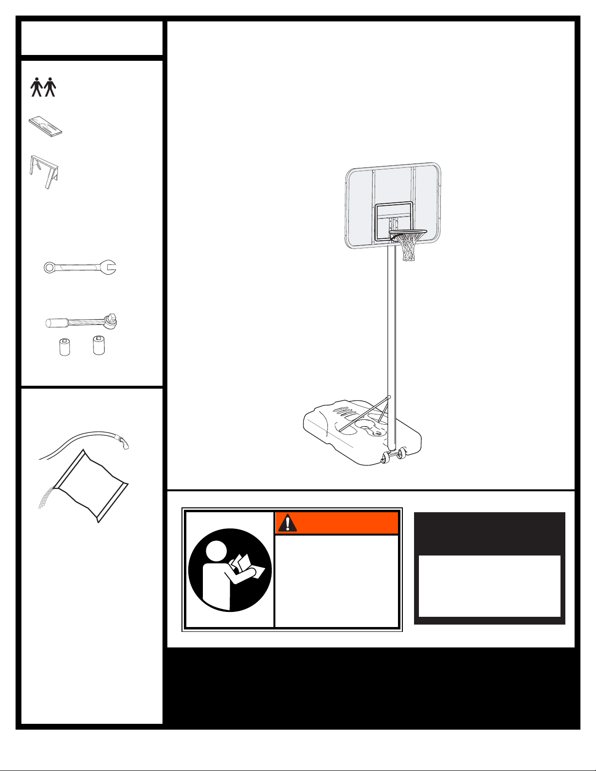
Por table System
•2 People
•Wood Board
(scrap)
•Sawhorse or
Support Table
•(2 each) Wrenches and/or
Socket Wrenches and
Sockets.
1/2" 3/4"
AND/OR
1/2" 3/4"
Owners Manual
Customer Service Center
• N53 W24700 South Corporate Circle • Sussex, WI 53089 • U.S.A.
•Garden Hose or Sand
SAND
SAND
(360 lb.)
(360 lb.)
(163 kg)
(163 kg)
WARNING!
READ AND UNDERSTAND
OPERATOR'S MANUAL
BEFORE USING THIS UNIT.
FAILURE TO FOLLOW
OPERATING INSTRUCTIONS
COULD RESULT IN INJURY
OR DAMAGE TO
PROPERTY.
Toll-Free Customer Service Number for U.S: 1-800-558-5234,
For Canada: 1-800-284-8339,
For Europe: 00 800 555 85234 (Sweden: 009 555 85234),
For Australia: 1-800-632 7921
Internet Address: http://www.huffysports.com
Write Model Number
From Box Here:
© COPYRIGHT 2005 by SPALDING
1
12/05 ID# M611411
Page 2
10-3/4" High
4" Wide
PMS 021 for Warning
Owner must ensure that all players know and follow these rules
for safe operation of the system.
WARNING
•
DO NOT HANG on the rim or any part of the system including
backboard, support braces or net.
•
During play, especially when performing dunk type activities,
keep player's face away from the backboard, rim and net.
Serious injury could occur if teeth/face come in contact with
backboard, rim or net.
•
Do not slide, climb, shake or play on base and/or pole.
•
After assembly is complete, fill system completely with water
or sand. Never leave system in an upright position without
filling base with weight, as system may tip over causing
injuries.
•
When adjusting height or moving system, keep hands and
fingers away from moving parts.
•
Do not allow children to move or adjust system.
•
During play, do not wear jewelry (rings, watches, necklaces,
etc.). Objects may entangle in net.
•
Surface beneath the base must be smooth and free of gravel or
other sharp objects. Punctures cause leakage and could cause
system to tip over.
•
Keep organic material away from pole base. Grass, litter, etc.
could cause corrosion and/or deterioration.
•
Check pole system for signs of corrosion (rust, pitting,
chipping) and repaint with exterior enamel paint. If rust has
penetrated through the steel anywhere, replace pole
immediately.
•
Check system before each use for proper ballast, loose
hardware, excessive wear and signs of corrosion and repair
before use.
•
Check system before each use for instability.
•
Do not use system during windy and/or severe weather
conditions; system may tip over. Place system in the storage
position and/or in an area protected from the wind and free
from personal property and/or overhead wires.
•
Never play on damaged equipment.
•
When moving system, use caution to keep mechanism from
shifting.
•
Keep pole top covered with cap at all times.
•
Do not allow water in tank to freeze. During sub-freezing
weather add 2 gallons of non-toxic antifreeze, sand or empty
tank completely and store. (Do not use salt.)
•
While moving system, do not allow anyone to stand or sit on
base or have added ballasting on base.
•
Do not leave system unsupervised or play on system when
wheels are engaged for moving.
•
Use Caution when moving system across uneven surfaces.
System may tip over.
•
Use extreme caution if placing system on sloped surface.
System may tip over more easily.
•
See instruction manual for proper installation and
maintenance.
Read and understand warnings listed
below before using this product.
Failure to follow these warnings may
result in serious injury and/or property
damage.
ID#: 556790 05/05
MUNSELL NOTATION
Hue Value Chroma
5.0 YR 6.0/15
Equiv. CIE Data
(Y%) x y
30.05 0.5510 0.4214
Approx. PMS Color
13 parts yellow
3 parts Warm Red
1/4 part Black
Warning Area = Orange
Size = 4" x 6.5"
Corner Radius = 3/8"
Die Cut Label
3.25 Mil Vinyl
All Temp. Permanent Adhesive
1 Mil. Polypropolyne Overlaminate
Illustrator 8.0 = EPS
Backing + 1/16 Circumference
Rolls of 500
In the U.S.: 1-888-713-5488
In the U.S.: 1-800-558-5234
Canada: 1-800-284-8339
In the U.S.: 1-800-334-9111
In the U.S.: 1-800-772-5346
5E2356 05/05
1
3
2
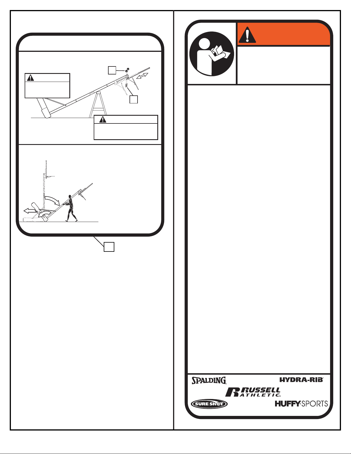
MOVING SYSTEM
1. While holding pole, rotate
basketball system forward
until wheels engage with
ground.
2. Move basketball system to
desired location.
3. Carefully rotate basketball
system upright.
4.
Check system for stability.
HEIGHT ADJUSTMENT
A
WARNING
B
WARNING
Do not adjust height of system
in upright position. System must
be in down position to adjust.
Rest unit on support table. Remove adjustment knobs (A)
and carriage bolts (B) to extend or retract backboard and rim.
Height adjustment from 7-1/2' to 10'.
4" x 5-1/2"
Backboard
may rotate during
height adjustment.
15
ID# M611411 12/05
2
Page 3
SAFETY INSTRUCTIONS
FAILURE TO FOLLOW THESE SAFETY INSTRUCTIONS MAY RESULT IN SERIOUS INJURY OR
PROPERTY DAMAGE AND WILL VOID WARRANTY.
Owner must ensure that all players know and follow these rules for safe operation of the system.
To ensure safety, do not attempt to assemble this system without following the instructions carefully. Proper
and complete assembly, use, and supervision are essential for proper operation and to reduce the risk of
accident or injury. A high probability of serious injury exists if this system is not installed, maintained, and
operated properly.
• If using a ladder during assembly, use extreme caution.
• Check base regularly for leakage. Slow leaks could cause the system to tip over
unexpectedly
• Seat the pole sections properly (if applicable). Failure to do so could allow the pole
sections to separate during play and/or during transport of the system.
• Climate, corrosion or misuse could result in system failure.
• If technical assistance is required, contact Customer Service.
• Minimum operational height is 6'-6" (1.98m) to the bottom of backboard.
Most injuries are caused by misuse and/or not following instructions.
Use caution when using this unit.
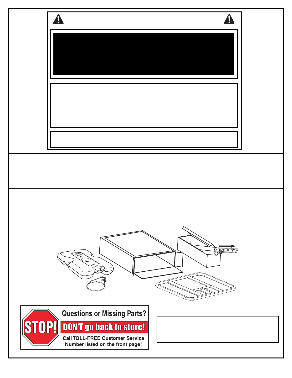
NOTICE TO ASSEMBLERS
ALL basketball systems, including those used for DISPLAYS, MUST be assembled and ballasted
with sand or water according to instructions. Failure to follow instructions could result in
SERIOUS INJURY. It is NOT acceptable to devise a makeshift weight system.
IMPORTANT!
Remove all contents from boxes.
Be sure to check inside pole sections;
hardware and additional parts are packed inside.
WARRANTY CARD:
Please remember to complete your product registration form either
on-line at:
www.huffysports.com/customer_support/product_registration
or mail-in the enclosed postcard.
3
12/05 ID# M611411
Page 4
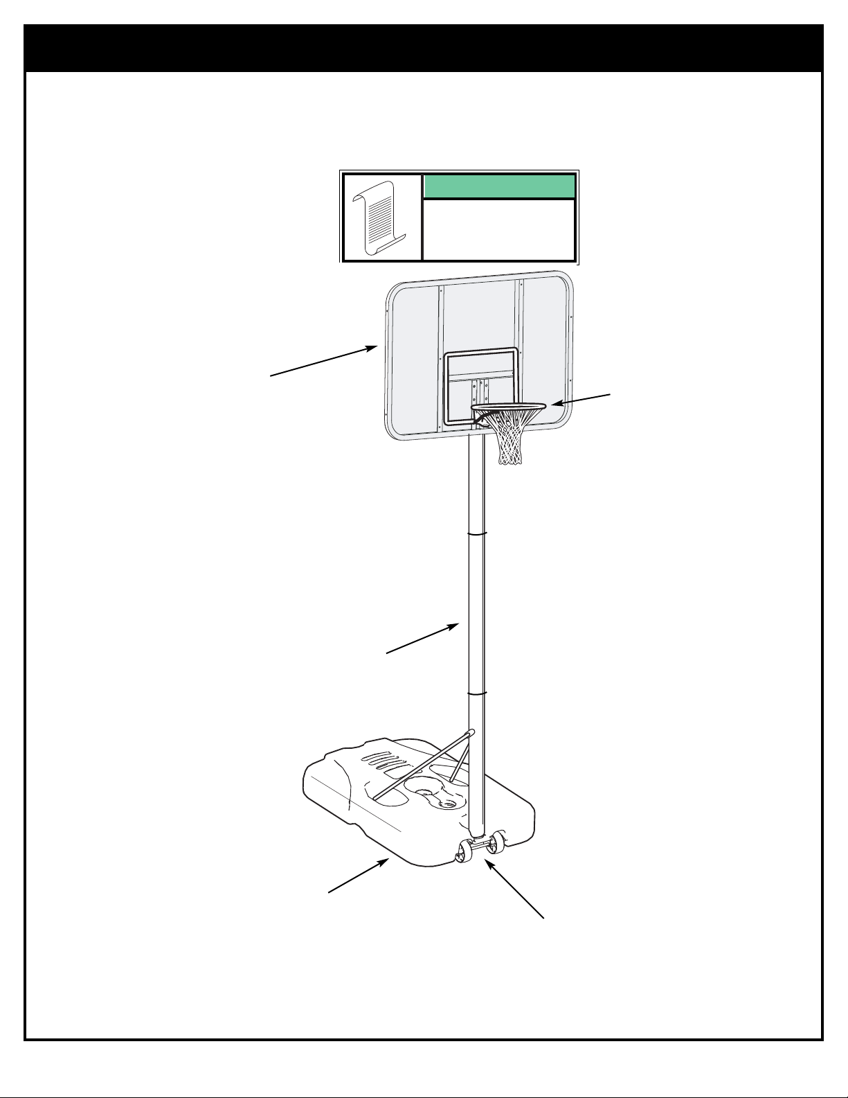
Get to know the basic parts of your basketball system...
FRONT VIEW
NOTE:
BOARD STYLE
MAY VARY
BOARD
RIM
POLE
ID# M611411 12/05
BASE
WHEEL
CARRIAGE
ASSEMBLY
4
Page 5
PARTS LIST
Item Qty. Part No. Description
1 1 206646 Tank (Black)
2 1 200628 Wheel Axle
3 2 226401 Wheel
4 1 908200 Top Pole Section
5 1 908246 Middle Pole Section with Label
6 1 900644 Bottom Pole Section Assembly
7 1 203041 Nut, Hex Flange, 3/8-16
8 1 Net
9 1 201342 Wheel Bracket
10 2 201651 Spacer, Wheel Axle
11 4 203104 Bolt, Hex-Flange 5/16-18 x 2" Long
12 1 206219 Cap
13 1 266001 Bolt, Carriage, 3/8-16 x 1.5 Long
14 1 203617 Tank Cap
15 1 5E2356 Label, Moving System and Height Adjust.
16 2* 203084 Bolt, Carriage, 5/16-18 x 1.75 Long
17 4* 201344 Knob, Plastic, 3-sided
18 1 Rim
19 1 203470 Washer, Flat 5/8 I.D. x 1-1/2 O.D.
20 2 900057 Backboard Mounting Bracket
21 1 203795 Nut, Special 3/8-NC
22 3 203309 Washer, .406 I.D. x 1.0 O.D.
23 2 203053 Bolt, Carriage 5/16-18 x 4
24 2 200837 Board Spacer
25 4* 203100 Nut, Hex Flange, 5/16-18
26 1 900033 Slam Jam Bracket, Black
27 1 203796 Bolt, “Tee” 3/8-NC x 5 Long
28 1 200318 Bracket Reinforcement, Slam Jam
29 1 203472 Spring, Black
30 1 Backboard
* YOU MAY HAVE EXTRA PARTS WITH THIS MODEL.
5
12/05 ID# M611411
Page 6

PPAARRTTSS IIDDEENNTTIIFFIIEERR
- Actual Size
#13 (1)
#16 (2*)
#11 (4)
#23 (2)
#21 (1)
#19 (1)
#25 (4*)
#22 (3)
#27 (1)
#7 (1)
#10 (2)
#1 (1)
#9 (1)
PARTS IDENTIFIER- Not Actual Size
#2 (1)
#30 (1)
#12 (1)
#14 (1)
#3 (2)
#17 (4*)
#8 (1)
#20 (2)
#18 (1)
ID# M611411 12/05
#24 (2)
#26 (1)
6
#28 (1)
#29 (1)
Page 7

1.
SSEECCTTIIOONN AA:: AASSSSEEMMBBLLEE TTHHEE PPOOLLEESS
Correctly identify each pole section. Poles have an identification sticker
that will be used as a reference point in the next step.
Reference Stickers
4
5
TOP MIDDLE BOTTOM
6
7
12/05 ID# M611411
Page 8

IMPORTANT!
TROUGH
GORGE
RINNE
CANAL
ONCE POLE SECTIONS ARE POUNDED TOGETHER- THEY CANNOT BE TAKEN APART
Align poles using alignment marks. First, pound top
CAUTION!
THE IDENTIFICATION STICKER IS
LOCATED 3-3/4" FROM THE END
O
F THE POLE. WHEN PROPERLY
POUNDED TOGETHER, THE POLE
SECTIONS SHOULD HAVE A 2-1/2"
M
INIMUM OVERLAP, LEAVING 11/4" BETWEEN THE OVERLAPPING
POLE AND THE IDENTIFICATION
STICKER.
FIG. B.
2.
FIG. A.
and middle poles together by bouncing them on a scrap
piece of wood on the ground as shown in FIG A. until
they no longer move toward pole identification stickers.
THEN add bottom pole section and pound together in
the same way FIG B.
4
IMPORTANT!
4
5
TROUGH
5"
5
1-1/2"
ID
STICKER
DIMPLE
6
HOLE
ID# M611411 12/05
Wood Scrap
(NOT SUPPLIED)
8
Page 9

3.
SECTION B: ASSEMBLE THE BASE
Install wheel axle (2) through wheel bracket (9) and install wheels (3) onto
wheel axle (2) with spacers (10) as shown.
IMPORTANT!:
9
4.
3
10
Attach wheel carriage assembly to base (1) with bolt (13), washer (22), and nut (7)
as shown. FINGER TIGHTEN - NO TOOLS REQUIRED. Assembly will be fully
tightened in next step.
2
THE SPACER (10) WILL
FIT LOOSELY UNTIL
SECURED INTO THE
CAVITY OF THE BASE.
7
22
IMPORTANT!:
BE SURE THAT THE
1
13
9
SQUARE PORTION OF THE
CARRIAGE BOLT (13) IS
PROPERLY SEATED IN
THE SQUARE CUT-OUT
THE WHEEL BRACKET.
12/05 ID# M611411
OF
Page 10

5.
Attach pole assembly to tank assembly as shown. Secure pole assembly to tank
and wheel bracket by turning the pole assembly clockwise as shown. Tighten
pole completely and further rotate pole until struts are aligned correctly as shown
in FIG B.
WARNING!
TWO PEOPLE REQUIRED
FOR THIS PROCEDURE.
FAILURE TO FOLLOW THIS
WARNING COULD RESULT
IN SERIOUS INJURY AND/OR
PROPERTY DAMAGE.
IMPORTANT!
The pole should be turned
approximately 7 complete
rotations to tighten properly.
When properly tightened, the
wheel bracket will be tight
against the base. An assistant
is recommended to hold the
base in place during this step.
ID# M611411 12/05
FIG B
10
Page 11

6.
Rotate struts down and bend struts outward to line up with holes on base as
shown. Secure free ends of tank struts to tank with carriage bolt (16), washer (22),
and knob (17) as shown. Repeat for other side.
WARNING!
KNOBS MUST BE TIGHTENED
COMPLETELY AND
CHECKED PERIODICALLY
FOR TIGHTNESS.
22
16
17
11
12/05 ID# M611411
Page 12

7.
Mount brackets (20 & 26) to backboard and finger tighten as shown.
NOTE: Final adjustments will be made in Step 10.
NOTE:
BOARD STYLE
MAY VARY
25
20
24
26
27
11
27
26
ID# M611411 12/05
12
Page 13

Install Slam Jam Rim to Backboard
8.
A
18
A • Fit rim (18) securely into bracket (26) as shown (Allow "T"-bolt (27) to slip through
center hole in rim (18).
B • Install reinforcement bracket (28) onto “T” bolt (27) as shown.
C • Install spring (29) onto “T” bolt (27) as shown.
D • Install special nut (21) and washer (19) onto “T” bolt (27).
E • Tighten nut (21) until flush with end of “T” bolt (27).
B
28
27
27
26
C
29
27
27
19
D
21
#28
19
E
21
13
12/05 ID# M611411
Page 14

9.
Support pole and tank assembly over support table.
Carefully slide backboard components onto pole.
WARNING!
TWO PEOPLE REQUIRED
FOR THIS PROCEDURE.
FAILURE TO FOLLOW THIS
WARNING COULD RESULT IN
SERIOUS INJURY AND/OR
PROPERTY DAMAGE.
10.
WARNING!
DO NOT LEAVE
ASSEMBLY UNATTENDED
WHEN EMPTY; IT MAY TIP
OVER.
While still in the horizontal position, carefully slide
backboard components onto pole. Secure
hardware at desired position as shown and tighten
all hardware completely at this time.
NOTE:
Peel protective
film from surface
of acrylic
backboard prior
to use.
SAWHORSE OR SUPPORT TABLE
17
12
23
11.
Attach net (8).
ID# M611411 12/05
1.
3.
2.
4.
14
Page 15

5
E2356 05/05
1
3
2
MOVING SYSTEM
1
. While holding pole, rotate
basketball system forward
until wheels engage with
ground.
2
. Move basketball system to
d
esired location.
3
. Carefully rotate basketball
s
ystem upright.
4
.
C
heck system for stability.
HEIGHT ADJUSTMENT
A
W
ARNING
B
W
ARNING
D
o not adjust height of system
i
n upright position. System must
b
e in down position to adjust.
R
est unit on support table. Remove adjustment knobs (A)
and carriage bolts (B) to extend or retract backboard and rim.
H
eight adjustment from 7-1/2' to 10'.
4" x 5-1/2"
Backboard
m
ay rotate during
h
eight adjustment.
12.
SAND
360 LBS.
(163 KG)
SAND
360 LBS.
(163 KG)
SAND
450 LBS
.
(204 KG)
Place assembled unit in desired location. Fill
tank with water (26 gallons/98.4 liters) or sand
(approx. 360 lb./163 kg) and snap tank cap
(14) in place.
CAUTION!
ADD TWO GALLONS (7.6
LITERS) OF NON-TOXIC
ANTIFREEZE IN SUBFREEZING CLIMATES.
WARNING!
TWO PEOPLE REQUIRED
FOR THIS PROCEDURE.
FAILURE TO FOLLOW THIS
WARNING COULD RESULT
IN SERIOUS INJURY AND/OR
PROPERTY DAMAGE.
13.
Attach height and moving label
(15) to front of pole as shown.
Regulation rim height is 10 feet.
CAUTION!
HEIGHT AND MOVING LABEL
MUST NOT OBSTRUCT
FACTORY ATTACHED
WARNING LABEL.
SAND
SAND
(360 lb.)
(360 lb.)
(163 kg)
(163 kg)
NOTE:
IF USING SAND:
2 GALLONS OF
ANTI-FREEZE IS
NOT
REQUIRED
WARNING!
DO NOT LEAVE
ASSEMBLY UNATTENDED
WHEN EMPTY; IT MAY TIP
OVER.
15
10 feet
(3.05 m)
15
12/05 ID# M611411
 Loading...