

Page 1
H
U
F
F
Y
HUFFY
SPOR
TS
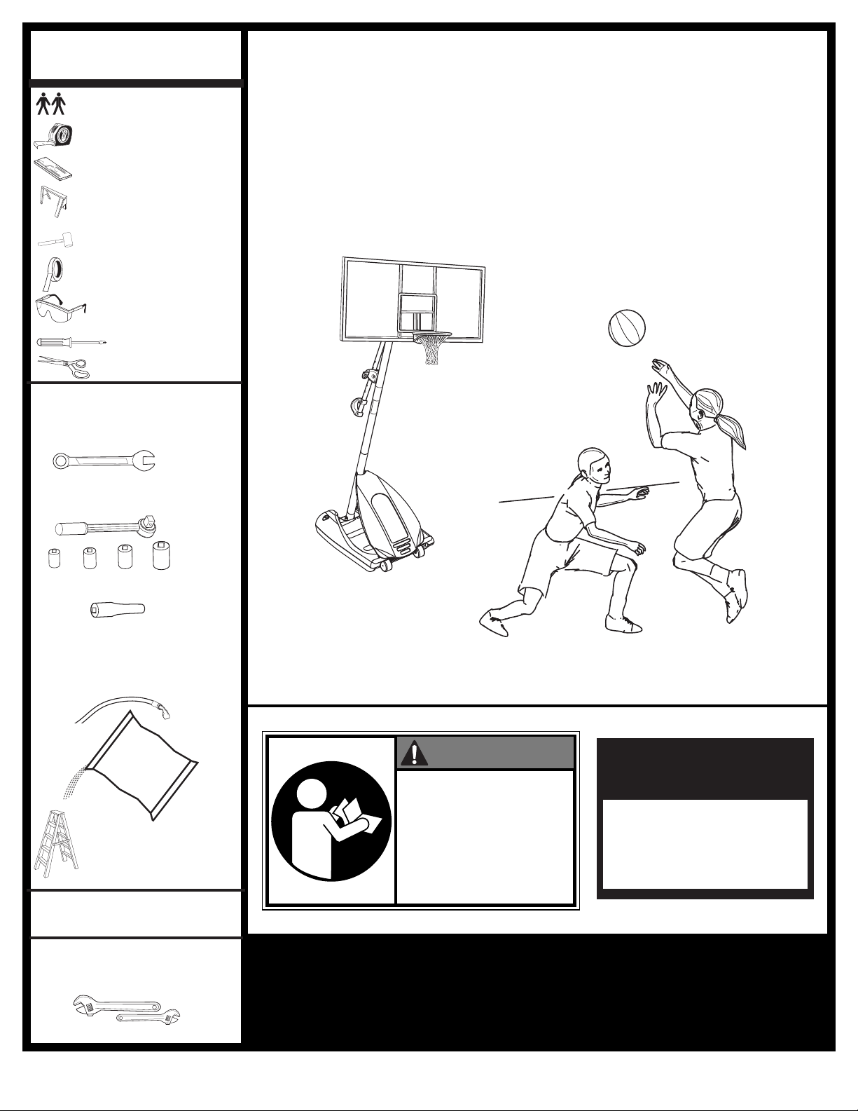
REQUIRED TOOLS
SAND
450 LBS
.
(204 KG)
AND MATERIALS:
• 2 People
Por table System
• Tape Measure
• Wood Board (scrap)
• Sawhorse or Support
Table
• Hammer
• Tape
• Safety Glasses
• Phillips Screwdriver
• Scissors
• (2 each) Wrenches and/or
Socket Wrenches and Sockets
(Deep-Well Sockets are
Recommended).
3/8" 1/2" 9/16" 3/4"
AND/OR
Owners Manual
Customer Service Center
• N53 W24700 South Corporate Circle • Sussex, WI 53089 • U.S.A.
3/8" 1/2" 9/16" 3/4"
• Extension is Recommended.
• Garden Hose or Sand
SAND
SAND
(360 lb.)
(360 lb.)
(163 kg)
(163 kg)
• Step Ladder - 8 ft. (2.4 m)
OPTIONAL TOOLS
AND MATERIALS:
• Large & Small Adjustable
Wrenches
WARNING!
READ AND UNDERSTAND
OPERATOR'S MANUAL
BEFORE USING THIS UNIT.
FAILURE TO FOLLOW
OPERATING INSTRUCTIONS
COULD RESULT IN INJURY
OR DAMAGE TO
PROPERTY.
Write Model Number
From Box Here:
Toll-Free Customer Service Number for U.S: 1-800-558-5234,
For Canada: 1-800-284-8339,
For Europe: 00 800 555 85234 (Sweden: 009 555 85234),
For Australia: 1-800-632 7921
Internet Address: http://www.huffysports.com
© COPYRIGHT 2005 by SPALDING
1
08/05 P/N M601111
Page 2
10-3/4" High
4" Wide
PMS 021 for Warning
Owner must ensure that all players know and follow these rules
for safe operation of the system.
WARNING
•
DO NOT HANG on the rim or any part of the system including
backboard, support braces or net.
•
During play, especially when performing dunk type activities,
keep player's face away from the backboard, rim and net.
Serious injury could occur if teeth/face come in contact with
backboard, rim or net.
•
Do not slide, climb, shake or play on base and/or pole.
•
After assembly is complete, fill system completely with water
or sand. Never leave system in an upright position without
filling base with weight, as system may tip over causing
injuries.
•
When adjusting height or moving system, keep hands and
fingers away from moving parts.
•
Do not allow children to move or adjust system.
•
During play, do not wear jewelry (rings, watches, necklaces,
etc.). Objects may entangle in net.
•
Surface beneath the base must be smooth and free of gravel or
other sharp objects. Punctures cause leakage and could cause
system to tip over.
•
Keep organic material away from pole base. Grass, litter, etc.
could cause corrosion and/or deterioration.
•
Check pole system for signs of corrosion (rust, pitting,
chipping) and repaint with exterior enamel paint. If rust has
penetrated through the steel anywhere, replace pole
immediately.
•
Check system before each use for proper ballast, loose
hardware, excessive wear and signs of corrosion and repair
before use.
•
Check system before each use for instability.
•
Do not use system during windy and/or severe weather
conditions; system may tip over. Place system in the storage
position and/or in an area protected from the wind and free
from personal property and/or overhead wires.
•
Never play on damaged equipment.
•
When moving system, use caution to keep mechanism from
shifting.
•
Keep pole top covered with cap at all times.
•
Do not allow water in tank to freeze. During sub-freezing
weather add 2 gallons of non-toxic antifreeze, sand or empty
tank completely and store. (Do not use salt.)
•
While moving system, do not allow anyone to stand or sit on
base or have added ballasting on base.
•
Do not leave system unsupervised or play on system when
wheels are engaged for moving.
•
Use Caution when moving system across uneven surfaces.
System may tip over.
•
Use extreme caution if placing system on sloped surface.
System may tip over more easily.
•
See instruction manual for proper installation and
maintenance.
Read and understand warnings listed
below before using this product.
Failure to follow these warnings may
result in serious injury and/or property
damage.
ID#: 556790 05/05
MUNSELL NOTATION
Hue Value Chroma
5.0 YR 6.0/15
Equiv. CIE Data
(Y%) x y
30.05 0.5510 0.4214
Approx. PMS Color
13 parts yellow
3 parts Warm Red
1/4 part Black
Warning Area = Orange
Size = 4" x 6.5"
Corner Radius = 3/8"
Die Cut Label
3.25 Mil Vinyl
All Temp. Permanent Adhesive
1 Mil. Polypropolyne Overlaminate
Illustrator 8.0 = EPS
Backing + 1/16 Circumference
Rolls of 500
In the U.S.: 1-888-713-5488
In the U.S.: 1-800-558-5234
Canada: 1-800-284-8339
In the U.S.: 1-800-334-9111
In the U.S.: 1-800-772-5346
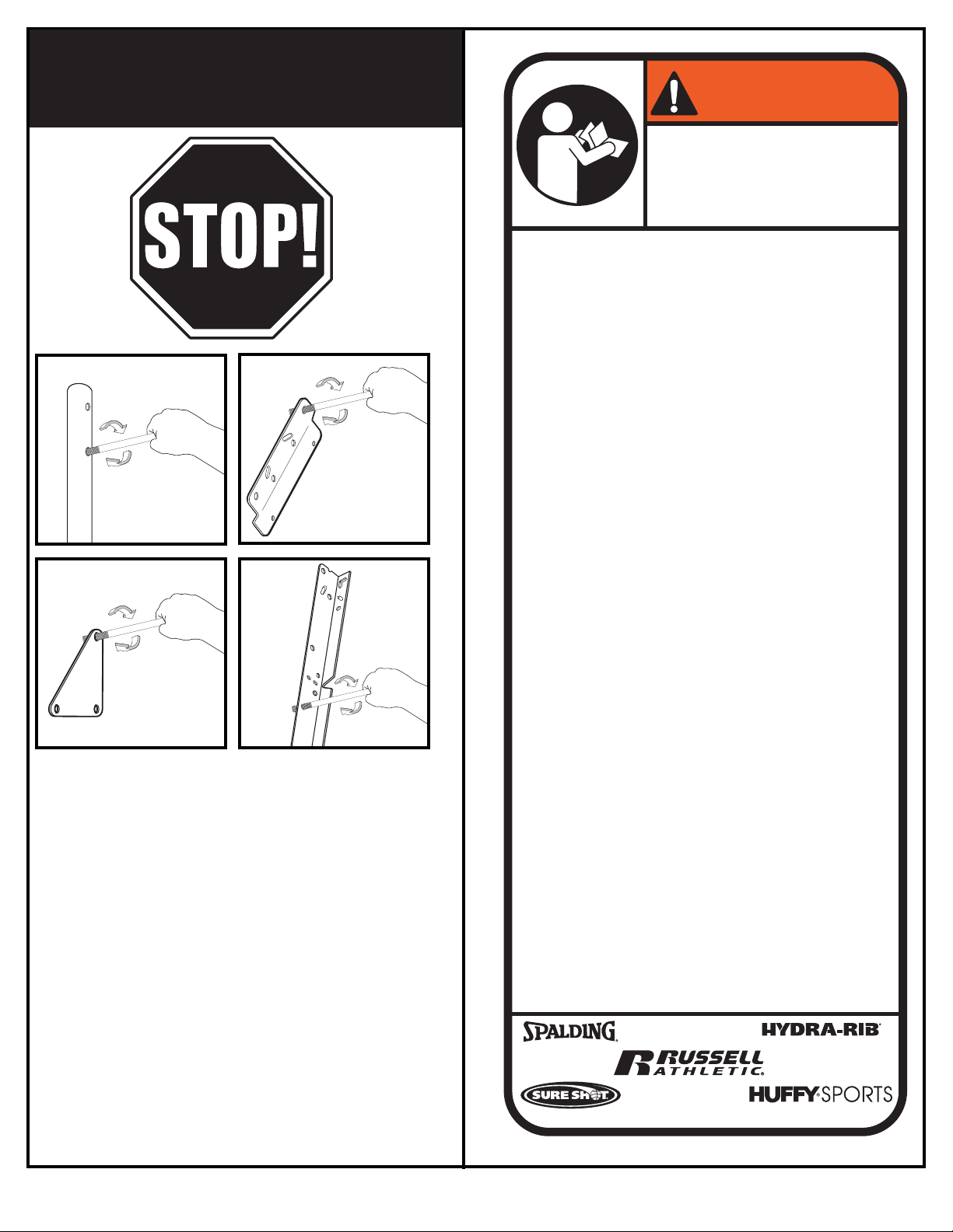
BEFORE YOU START!
o ensure optimal playability of backboard system, a
T
close tolerance fit between the elevator components
and hardware is required. Test-fit large bolts into large
holes of elevator tubes, backboard brackets, and
motion to ream out any excess paint from holes if
Not all items pictured are included with every model.
triangle plates. Carefully rock them in a circular
necessary
.
P/N M601111 08/05
2
Page 3
SAFETY INSTRUCTIONS
Size = 4" x 5.5"
Corner Radius = 3/8"
Die Cut Label
3.25 Mil Vinyl
All Temp. Permanent Adhesive
1 Mil. Polypropolyne Overlaminate
Illustrator 8.0 = EPS
Backing + 1/16 Circumference
Rolls of 500
2
2
1
3
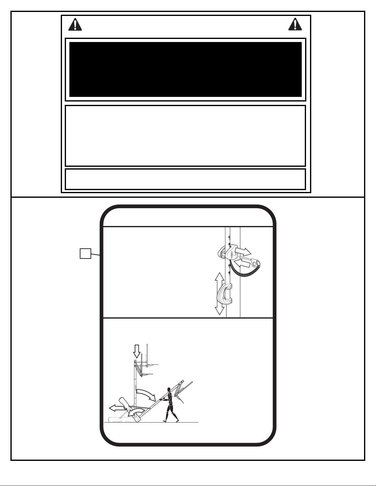
TO ADJUST BACKBOARD:
1. While holding handle, remove pin.
2. Move elevator up or down to
desired height.
3. Replace pin full length to lock
system at desired height.
511679 05/05
1
2
4
3
MOVING SYSTEM
Adjust basketball backboard
height to lowest position.
While holding pole, rotate
basketball system forward
until wheels engage with
ground.
Move basketball system to
desired location.
Carefully rotate basketball
system upright.
1.
2.
3.
4.
5.
Check system for stability.
HEIGHT ADJUSTMENT
FAILURE TO FOLLOW THESE SAFETY INSTRUCTIONS MAY RESULT IN SERIOUS INJURY,
PROPERTY DAMAGE AND WILL VOID WARRANTY.
Owner must ensure that all players know and follow these rules for safe operation of the system.
To ensure safety, do not attempt to assemble this system without following the instructions carefully. Proper
and complete assembly, use and supervision is essential for proper operation and to reduce the risk of
accident or injury. A high probability of serious injury exists if this system is not installed, maintained, and
operated properly.
• If using a ladder during assembly, use extreme caution.
• Check base regularly for leakage. Slow leaks could cause the system to tip over
unexpectedly
• Seat the pole sections properly (if applicable). Failure to do so could allow the pole
sections to separate during play and/or during transport of the system.
• Climate, corrosion or misuse could result in system failure.
• If technical assistance is required, contact Huffy Sports.
• Minimum operational height is 6’6” (1.98m) to the bottom of backboard.
Most injuries are caused by misuse and/or not following instructions.
Use caution when using this unit.
42
3
08/05 P/N M601111
Page 4
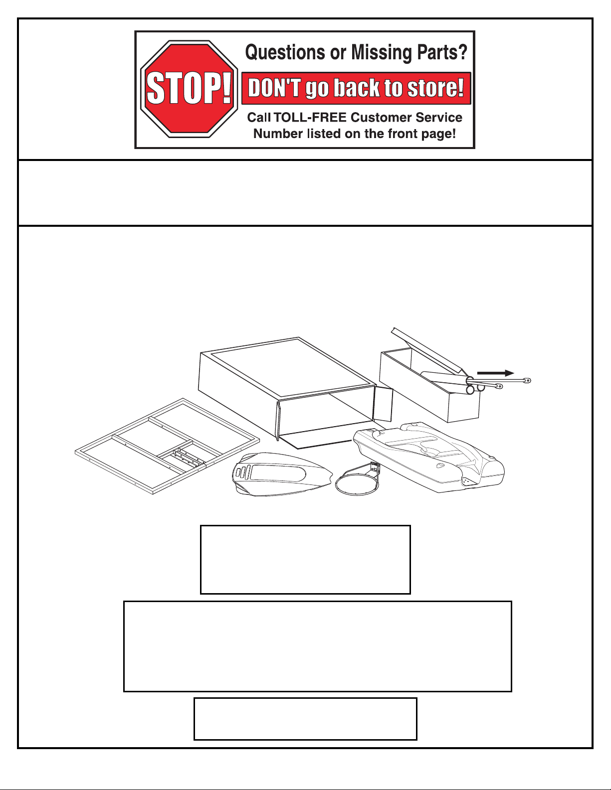
NOTICE TO ASSEMBLERS
ALL Huffy Sports Basketball Systems, including those used for DISPLAYS, MUST be assembled
and ballasted with sand or water according to the instructions. Failure to follow instructions
could result in SERIOUS INJURY. It is NOT acceptable to devise a makeshift weight system.
IMPORTANT!
Remove all contents from boxes.
Be sure to check inside pole sections;
hardware and additional parts are packed inside.
P/N M601111 08/05
WARRANTY CARD:
Please remember to complete your product
registration form either on-line at:
www.huffysports.com or mail-in the
enclosed postcard.
WARNING: IF YOUR SYSTEM IS EQUIPPED WITH AN ACRYLIC BACKBOARD,
EXAMINE BACKBOARD FOR ANY DAMAGE THAT MAY HAVE OCCURRED
DURING SHIPMENT. CRACKS IN THE BACKBOARD COULD RESULT IN
SUDDEN BREAKAGE. IF BACKBOARD IS DAMAGED IN ANY WAY PRIOR TO OR
AFTER ASSEMBLY, CALL TOLL-FREE NUMBER:
U.S. 1-800-558-5234; CANADA: 1-800-284-8339; http://www.huffysports.com
For more information on assembly, placement, proper
use, and maintenance, visit The American Basketball
Council website at http://www.smarthoops.com.
4
Page 5
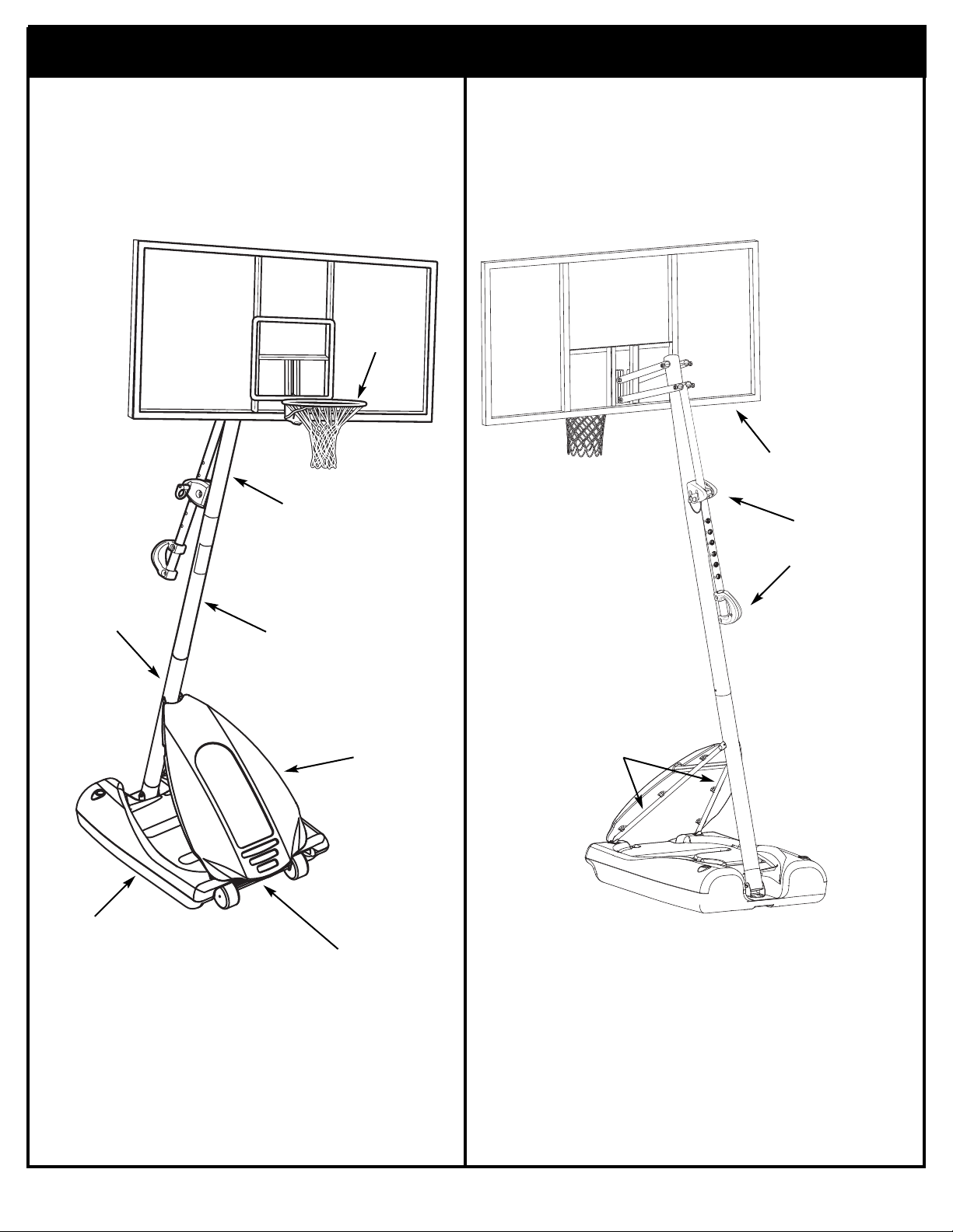
Get to know the basic parts of your basketball system...
FRONT
TOP POLE
BACK
RIM
BACKBOARD
ELEVATOR
ASSEMBLY
BOTTOM
POLE
BASE
MIDDLE
POLE
COVER
WHEEL
CARRIAGE
ASSEMBLY
FRONT
STRUTS
5
08/05 P/N M601111
Page 6
PARTS LIST - See Hardware Identifier
Item Qty. Part No. Description
1 1 908026 Top Pole Section
2 1 90810701 Middle Pole Section (with Label
3 1 908015 Bottom Pole Section
4 1 900223 Wheel Bracket
1 206940 Axle
5
6 2 226403 Wheel
7 2 206938 Pushnut
8 1 206660 Base
9 6 203156 Hex Bolt, 5/16-18 x 1
10 18* 203218 Flat Washer, 5/16
11 15* 203100 Hex-Flange Nut, 5/16-18
12 1 201581 Pole Bracket
13 2 202662 Hex Bolt, 5/16-18 x 4.5
14 2 203099 Lock Nut, 5/16-18
15 4 203223 Carriage Bolt, 5/16-18 x 1
16 2 906410 Tank Strut
17 1 200516 Bolt Cover
18 1 206990 Reinforcement Bracket
19 3 203038 Carriage Bolt, 5/16-18 x 2-3/4 Long
20 8 202862 Spacer, Plastic, 1.19" Long
21 7 206340 Lock Nut, 1/2-13
22 2 203053 Carriage Bolt, 5/16-18 x 4 Long
23 1 204872 Label, Height Indicator
24 2 204858 Spacer, Plastic, Biscuit
25 1 207103 Pole Cap
26 1 204853 Lanyard, Black Coil
27 1 204850 Pin, Locking
28 1 204832 Bracket, Pole Mount
29 4 206360 Hex Bolt, 3/8-16 x 2.625
30 6 203063 Nylon Insert Lock Nut, 3/8-16
31 4 201124 Lock Nut, 3/8-16
32 2 900867 Plate, Triangle
33 2 904807 Elevator Tube, Upper - Short
34 2 900183 Elevator Tube, Lower - Long
35 2 204859 Cover, Pin Slide
Item Qty. Part No. Description
36 2 204838 Spring, Counter Balance
37 2 203617 Base Plug
38 1 201965 Front Cover
39 4* 203257 Tie Straps
0 1 200504 Rim Cover
4
41 2 200520 Screw, #8 x .75
42 1 511679 Label, Height Adj and Moving
43 2 204857 Spacer, Metal 1/2” O.D. x 1.44 Long
44 1 205226 Left Board Pad
45 1 205225 Right Board Pad
46 6* 201596 Sheet Metal Screw, #14 x 1.25
47 6* 206303 Flat Washer, 1/4
48 1 205241 Center Board Pad
49 1 202856 Bolt, Hex, 1/2-13 x 4" Long
50 4 203232 Flat Washer, 3/8
51 1 202795 Label, NBA
52 2 90096401 Bracket, Backboard Support
53 4 201681 Spacer, Plastic, .530 I.D. x .88 Long
54 2 203103 Carriage Bolt, 5/16-18 x 2 Long
55 1 204803 Screw, Phillips Head
56 4 201682 Spacer, .530 I.D. x 1.875
57 6 202532 Bolt, Hex, 1/2-13 x 9.5"
58 1 904866 Height Adjustment Rod
59 1 204855 Handle, Left
60 1 204856 Handle, Right
61 1 900033 Bracket, Slam Jam
62 1 200318 Bracket, Reinforcement, Slam Jam
63 1 203470 Washer Flat, Slam Jam
64 1 203472 Spring, Black, Slam Jam
65 1 203795 Nut, Special, Slam Jam
66 1 203796 T-Bolt, 3/8-16 x 5 Long
67 Rim
68 4 205528 Bolt, Hex Flange, 5/16-18 x 1 Long
68 1 Net
*You may have extra parts with this model.
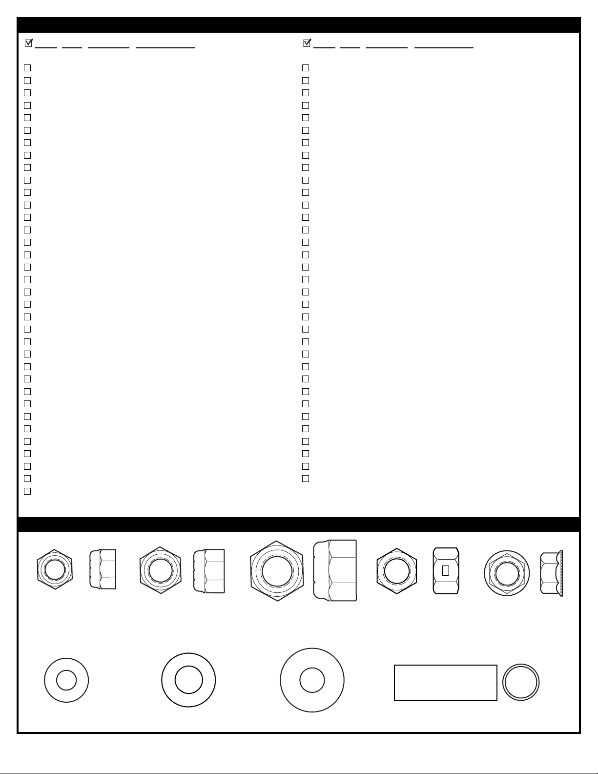
Item #14 (2)
Item #47 (6)*
P/N M601111 08/05
HARDWARE IDENTIFIER (NUTS, WASHERS & METAL SPACERS)
Item #30 (4)
Item #21 (7)
Item #31 (4)
Item #43 (2)
Item #50 (4)
Item #10 (18)*
6
Item #11 (15)*
Page 7
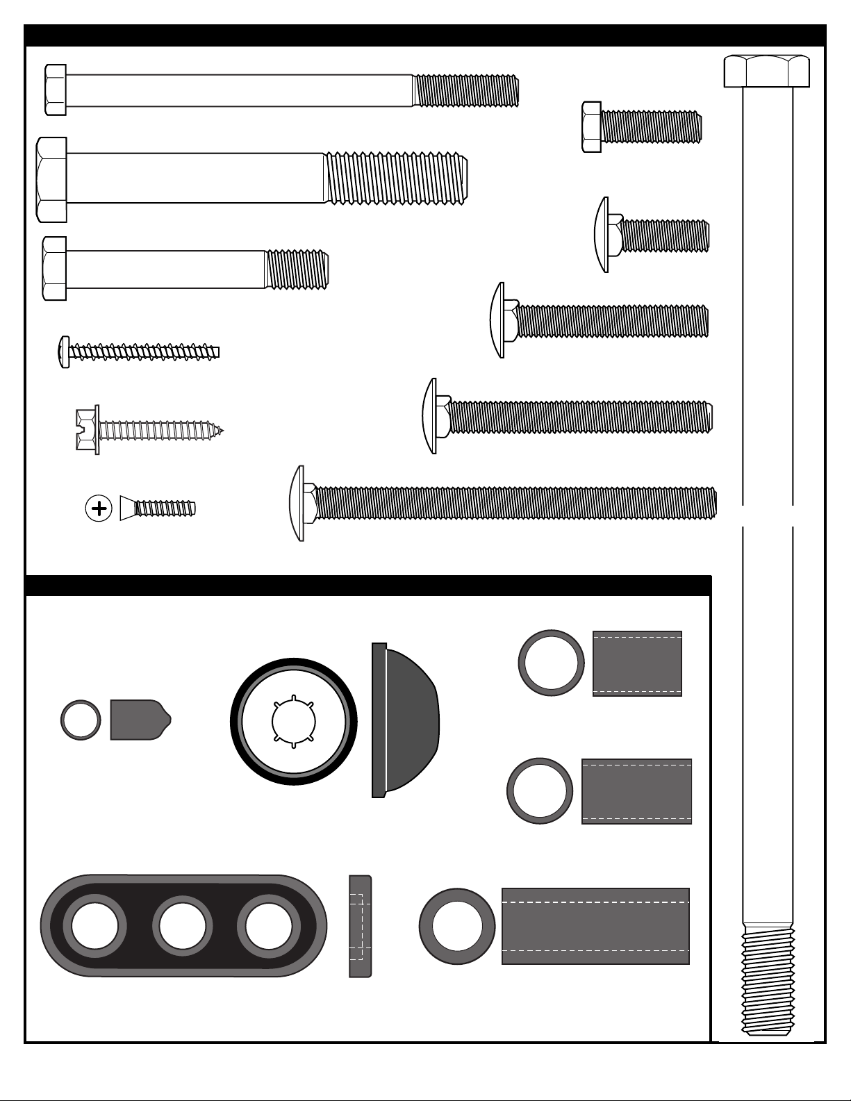
Item #29 (4)
Item #55 (1)
HARDWARE IDENTIFIER (BOLTS & SCREWS)
Item #13 (2)
Item #9 (6)
Item #49 (1)
Item #15 (4)
Item #54 (2)
Item #46 (6)
Item #41 (2)
HARDWARE IDENTIFIER (PLASTIC SPACERS & CAPS)
Item #17 (1)
Item #19 (1)
Item #57 (6)
Item #22 (2)
Item #53 (4)
Item #7 (2)
Item #20 (8)
Item #24 (2)
Item #56 (4)
7
08/05 P/N M601111
Page 8
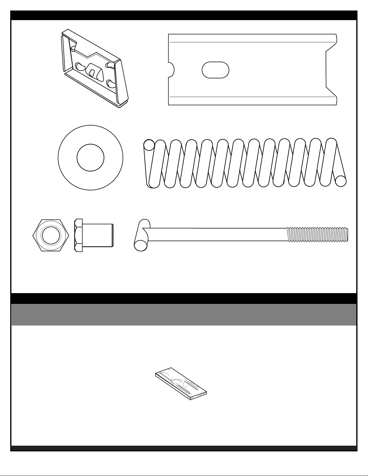
HARDWARE IDENTIFIER (RIM)
Item #61 (1)
Item #63 (1)
Item #65 (1)
Item #62 (1)
Item #64 (1)
Item #66 (1)
P/N M601111 08/05
SECTION A:
TOOLS REQUIRED FOR THIS SECTION
ASSEMBLE THE POLES
Wood Board (scrap)
8
Page 9
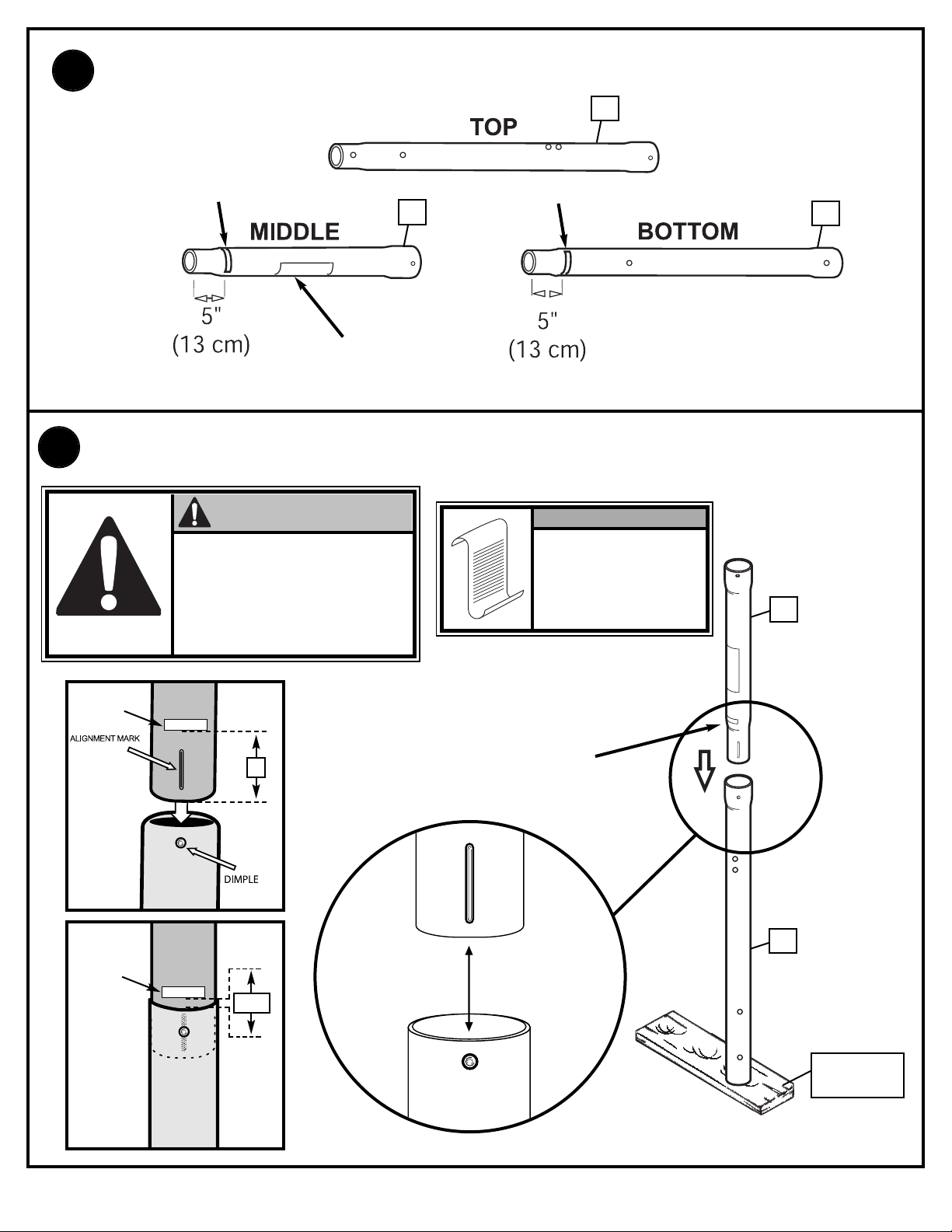
1.
Correctly identify each pole section.
1
I.D. Label
I.D. Label
2
WARNING
LABEL
Bounce middle pole (2) into top pole section (1) using a wood scrap as shown until top
2.
pole no longer moves toward pole identification mark on middle pole.
CAUTION!
THE IDENTIFICATION STICKER IS
LOCATED 5" FROM THE END OF THE
POLE. WHEN PROPERLY POUNDED
TOGETHER, THE POLE SECTIONS
SHOULD HAVE A 3-1/2" MINIMUM
OVERLAP, LEAVING 1-1/2" BETWEEN
THE OVERLAPPING POLE AND THE
IDENTIFICATION STICKER.
NOTE:
POLE SECTIONS
SHOULD HAVE A
3-1/2" (9 CM)
MINIMUM
OVERLAP.
3
2
IDENTIFICATION
STICKER
IDENTIFICATION
STICKER
middle pole
middle pole
5"
1-1/2"
POLE
IDENTIFICATION
MARK
1
WOOD SCRAP
(NOT SUPPLIED)
9
08/05 P/N M601111
Page 10

Align dimple of middle pole with slot of bottom pole.While maintaining alignment, bounce
3.
top and middle pole assembly (1 & 2) onto lower pole section (3) as shown until they no
longer move toward pole identification mark.
CAUTION!
THE IDENTIFICATION STICKER IS
LOCATED 5" FROM THE END OF
THE POLE. WHEN PROPERLY
POUNDED TOGETHER, THE POLE
SECTIONS SHOULD HAVE A 3-1/2"
MINIMUM OVERLAP, LEAVING 1-1/2"
BETWEEN THE OVERLAPPING
POLE AND THE IDENTIFICATION
STICKER.
NOTE:
POLE SECTIONS
SHOULD HAVE A
3-1/2" (9 CM)
MINIMUM
OVERLAP.
IDENTIFICATION
STICKER
1
IDENTIFICATION
STICKER
ottom Pole
B
Bottom Pole
5"
1-1/2"
POLE
IDENTIFICATION
MARK
WOOD SCRAP
(NOT SUPPLIED)
2
RODS SHOWN ARE
FOR VISUAL
REPRESENTATION
OF ALIGNMENT
AND ARE NOT
SUPPLIED WITH
3
THE HARDWARE
IMPORTANT!
Holes in top (1) and bottom (3)
pole sections MUST align to
correctly position elevator
system toward playing
surface.
P/N M601111 08/05
10
Page 11

SECTION B: ASSEMBLE THE BASE
This is what your system will look like
when you’ve finished this section:
(2) 1/2”Wrenches
TOOLS REQUIRED FOR THIS SECTION
(2) Socket Wrenches
and Sockets
AND/OR
AND
Hammer or
Mallet
1/2”
11
08/05 P/N M601111
Page 12

1.
Assemble pole bracket (12) using bolt (13) and
Lock Nut (14) as shown.
2.
Attach pole assembly to base
using carriage bolts (15)
washers(10) and nuts (11) as
shown. Two people are required
for this step.
IMPORTANT!
DO NOT OVER
TIGHTEN
13
WARNING!
TWO PEOPLE REQUIRED
FOR THIS PROCEDURE.
FAILURE TO FOLLOW THIS
WARNING COULD RESULT
IN SERIOUS INJURY AND/OR
PROPERTY DAMAGE.
14
12
15
IMPORTANT!
P/N M601111 08/05
12
11
10
THE CUT CORNERS OF
THE POLE BRACKET
NEED TO FACE TOWARD
THE BACK OF THE BASE
AS SHOWN.
Page 13

Secure tank struts (16) to pole as shown.
3.
Nut should be tightened until flush (even) with lock nuts outer edge. Place cap (17) over
exposed end of bolt as shown.
10
10
17
13
14
TWO PEOPLE REQUIRED
FOR THIS PROCEDURE.
16
Rotate non-secured ends of tank struts (16) outward to mounting holes in tank as
4.
FAILURE TO FOLLOW THIS
WARNING COULD RESULT
IN SERIOUS INJURY AND/OR
PROPERTY DAMAGE.
WARNING!
shown.Secure ends of tank struts (16) to tank as shown. Repeat for opposite side.
16
13
9
16
10
10
11
08/05 P/N M601111
Page 14

Insert axle (5) through wheel bracket (4). Secure wheels (6) to axle using pushnuts (7).
5.
Carefully tap pushnuts onto axle with hammer or mallet
IMPORTANT!
6
7
4
SIDE OF WHEEL WITH
LONGER PLASTIC AXLE
NEEDS TO FACE THE
WHEEL BRACKET.
6
7
5
Install wheel assembly to base (8) using bolts(9),
6.
washers(10) and nuts (11) as shown.
NOTE:
CAREFULLY TIPPING THE
SYSTEM ON IT'S SIDE WILL
ALLOW EASIER ACCESS
TO THE UNDERSIDE OF
BASE.
8
9
10
P/N M601111 08/05
14
10
1
1
Page 15

SECTION C: ASSEMBLE THE ELEVATOR & BACKBOARD
This is what your system will look like
when you’ve finished this section:
TOOLS REQUIRED FOR THIS SECTION
(1) 3/8”, (2) 1/2”, (2) 9/16” and
(2) 3/4” Wrenches
Phillips Screwdriver
AND/OR
(2) Socket Wrenches and Sockets
3/8”
1/2”
9/16”
3/4”
15
08/05 P/N M601111
Page 16

Install pole mount bracket (28) and reinforcement bracket (18) with carriage bolts (22) as
1.
shown. Tighten flange nuts (11) completely.
18
1
28
11
11
Attach spacers (24, 43) to pole mount bracket (28) with bolts (29), washers (50), and lock
2.
22
22
nuts (31) as shown.
P/N M601111 08/05
IMPORTANT!
Tighten just until
washers (50) stop
moving.
43
24
31
43
28
50
50
50
50
29
24
16
Page 17

Assemble lanyard (26) to locking pin (27) as shown (FIG A). Attach covers (35) onto pole
3.
mount bracket (28) with carriage bolt (19) and nut (11) as shown.
FIG. A
11
35
IMPORTANT!
19
26
Apply logo and height indicator labels (23) to
4.
adjustment rod (58) as shown. Attach handle parts
(59, 60) to adjustment rod with screw (55), carriage
bolts (54), and flange nuts (11) as shown.
Loop end of pin
lanyard (26) over
carriage bolt (19) as it
passes through the
pole mount bracket (28)
27
during this assembly.
23
28
26
35
19
27
58
IMPORTANT!
Indicator labels should
be applied as close to
holes as possible to
prevent labels from
being damaged during
height adjustment.
17
11
23
11
60
54
55
59
54
08/05 P/N M601111
Page 18

27
Insert handle assembly through pole mount assembly as
5.
shown. Lock pole assembly in place at the 10’ (3.05 m)
mark with pin (27).
30
30
6.
Assemble backboard brackets (52)
using bolts (29), and nuts (30) as
shown.
29
52
29
52
P/N M601111 08/05
18
Page 19

7.
A
Assemble board pad to board.
Work from the center - out.
Using the holes which line up for your
board size, attach center pad (48), right
pad (45) and left pad (44) sections to
board using screws (46) and washers (47)
as shown.
IMPORTANT!
DO NOT TIGHTEN
HARDWARE
COMPLETELY.
BOARD STYLE MAY
VARY
Secure left (44) and right (45) pad sections to
B
board by pushing pads over the corners of the
board. Secure completely by using screws (46)
and washers (47) as shown.
IMPORTANT!
TIGHTEN ALL
HARDWARE
COMPLETELY.
44
47
46
46
48
47
45
47
46
45
BOARD STYLE MAY
VARY
46
44
47
19
47
46
48
47
46
08/05 P/N M601111
Page 20

Identify elevator tubes (33 & 34).
8.
Toward
Board
Toward
Board
Upper Elevator tube
Lower Elevator tube
33
34
Toward
Pole
Toward
Pole
Attach lower elevator tubes (34) and counter balance spring (36) to backboard support
brackets (52) using spacers (53 & 56), bolt (57), and nut (21) as shown.
53
57
56
34
36
52
56
52
36
21
34
66
52
P/N M601111 08/05
68
20
Page 21

Attach upper elevator tubes (33) to backboard support brackets (52) using spacers
9.
(53), bolt (57), and nut (21) as shown.
IMPORTANT!
Tighten ALL Hardware
from Steps 6-8 After this
Assembly is Completed.
53
56
57
56
21
52
33
53
21
56
33
57
56
33
33
21
08/05 P/N M601111
Page 22

10.
Support pole on sawhorse. Attach backboard assembly to top pole section (4) as
shown. Install pole cap (25).
11.
WARNING!
U
SE CAUTION; ELEVATOR
A
SSEMBLY IS HEAVY.
T
WO PEOPLE REQUIRED FOR
THIS PROCEDURE. FAILURE
TO FOLLOW THIS WARNING
C
OULD RESULT IN SERIOUS
INJURY AND/OR PROPERTY
DAMAGE.
1
20
32
20
57
Install upper elevator tubes (33) to triangle plates (63) as shown. Install handle assembly
to lower elevator tubes (34) using bolt (57), spacers (20), and nut (21) as shown.
21
34
21
25
32
49
34
58
1
NOTE:
Before going on to
next step, set
adjustable system
assembly to the
10’ (3.05 m) setting.
20
57
20
34
57
21
21
33
20
34
32
34
20
33
P/N M601111 08/05
22
Page 23

12.
A. Fit rim (67) securely into bracket (61) as shown. Allow T-bolt (66) to slip through center hole
in rim (67).
B. Install reinforcement bracket (62) onto T-bolt (66) as shown.
C. Install spring (64) onto T-bolt (66) as shown.
D. Install special nut (65) and washer (63) onto T-bolt (66).
E. Tighten special nut (65) until flush with end of T-bolt (66).
Install Rim to Backboard
A.
67
C.
64
66
61
B.
D.
63
62
65
NOTE:
ORIENTATION
OF BRACKET
66
62
66
E.
66
65
63
23
08/05 P/N M601111
Page 24

13.
Install net (43).
A.
14.
B.
C.
D.
Insert bolt (57) through left side upper elevator tube (33), then stretch spring (36) onto
bolt (57). Insert bolt (57) through right side upper elevator tube (33) and secure with
nut (21).
WARNING!
USE EYE PROTECTION
WHEN INSTALLING
SPRINGS.
NOTE:
Peel protective
film from surface
of acrylic
backboard prior
to use.
57
36
36
33
21
33
58
P/N M601111 08/05
24
Page 25

SECTION D: FILL BASE
SAND
450 LBS
.
(204 KG)
SAND
450 LBS
.
(204 KG)
TOOLS REQUIRED FOR THIS SECTION
Garden Hose or Sand
SAND
SAND
(360 lb.)
(360 lb.)
(163 kg)
(163 kg)
Roll assembly to desired playing area. Fill base (8) with water (approx. 40 gallons) and
1.
snap base plugs (37) in place.
WARNING!
DO NOT LEAVE
ASSEMBLY UNATTENDED
WHEN EMPTY; IT MAY TIP
OVER.
WARNING!
TWO PEOPLE REQUIRED
FOR THIS PROCEDURE.
FAILURE TO FOLLOW THIS
WARNING COULD RESULT IN
SERIOUS INJURY AND/OR
PROPERTY DAMAGE.
CAUTION!
37
8
ADD TWO GALLONS (7.6 LITERS)
OF NON-TOXIC ANTIFREEZE IN
SUB-FREEZING CLIMATES.
37
SAND
SAND
(360 lb.)
(360 lb.)
(163 kg)
(163 kg)
NOTE:
IF USING SAND:
2 GALLONS OF
ANTI-FREEZE IS
NOT
REQUIRED
25
08/05 P/N M601111
Page 26

SECTION E: INSTALL FRONT COVER
TOOLS REQUIRED FOR THIS SECTION
Scissors
Install front cover (38) by lining up stand-offs along the tank struts. Insert a tie strap (39)
1.
through the top two and bottom two stand offs. Wrap tie straps around tank struts as
shown and secure tightly. Trim excess of tie strap as shown in FIG.A.
39
38
STANDOFFS
FIG. A
P/N M601111 08/05
26
Page 27

Phillips
Screwdriver
SECTION F: INSTALL RIM COVER
TOOLS REQUIRED FOR THIS SECTION
1.
Install cover (40) over spring return mechanism with screws (41) as shown.
Place NBA label (51) on front of rim cover (40).
41
41
40
27
51
08/05 P/N M601111
Page 28

SECTION G: HEIGHT ADJUSTMENT AND MOVING LABEL
S
ize = 4" x 5.5"
C
orner Radius = 3/8"
Die Cut Label
3.25 Mil Vinyl
All Temp. Permanent Adhesive
1 Mil. Polypropolyne Overlaminate
Illustrator 8.0 = EPS
Backing + 1/16 Circumference
Rolls of 500
2
2
1
3
TO ADJUST BACKBOARD:
1. While holding handle, remove pin.
2. Move elevator up or down to
desired height.
3. Replace pin full length to lock
system at desired height.
511679 05/05
1
2
4
3
MOVING SYSTEM
Adjust basketball backboard
height to lowest position.
While holding pole, rotate
basketball system forward
u
ntil wheels engage with
ground.
Move basketball system to
desired location.
Carefully rotate basketball
s
ystem upright.
1.
2.
3.
4.
5.
Check system for stability.
HEIGHT ADJUSTMENT
Apply Height Adjustment and Moving Label (42) to front of pole, where it is clearly
1.
visible.
A. While holding handle, remove pin (27).
2.
B. Move elevator up or down to desired height.
C. Replace pin (27) full length to lock system at
desired height.
P/N M601111 08/05
WARNING!
DO NOT ALLOW
CHILDREN TO
ADJUST HEIGHT.
28
42
27
A.
58
C.
B.
 Loading...