


SY-6VBA 133
Motherboard
Quick Start Guide
|
|
|
|
|
Introduction |
|
|
|
|
|
|
|
Hardware |
Installation |
|
|
|
|
|
|
Quick BIOS |
Setup |
|
|
|
|
|
|
The SOYO CD |
|
|
|
|
|
|
|
|
|
|
Tested To Comply
FCWith FCC Standards
FOR HOME OR OFFICE USE
POST CONSUMER 100% RECYCLED PAPER

SOYO ™
SY-6VBA 133 Motherboard
Pentium® III, Pentium® II & CeleronTM processors Via Apollo Pro133 AGP/PCI Motherboard 66/100/133 MHz Front Side Bus supported ATX Form Factor
Copyright © 1999 by Soyo Computer Inc.
Trademarks:
Soyo is a registered trademark of Soyo Computer Inc. All trademarks are the property of their owners.
Product Rights:
Product and corporate names mentioned in this publication are used for identification purposes only and may be registered trademarks or copyrights of their respective companies.
Copyright Notice:
All rights reserved. This manual is copyrighted by Soyo Computer Inc. You may not reproduce, transmit, transcribe, store in a retrieval system, or translate into any language, in any form or by any means, electronic, mechanical, magnetic, optical, chemical, manual or otherwise, any part of this publication without express written permission of Soyo Computer Inc.
Disclaimer:
Soyo Computer Inc. makes no representations or warranties regarding the contents of this manual. We reserve the right to revise the manual or make changes in the specifications of the product described within it at any time without notice and without obligation to notify any person of such revision or change. The information contained in this manual is provided for general use by our customers. Our customers should be aware that the personal computer field is the subject of many patents. Our customers should ensure that their use of our products does not infringe upon any patents. It is the policy of Soyo Computer Inc. to respect the valid patent rights of third parties and not to infringe upon or assist others to infringe upon such rights.
Restricted Rights Legend:
Use, duplication, or disclosure by the Government is subject to restrictions set forth in subparagraph (c)(1)(ii) of the Rights in Technical Data and Computer Software clause at 252.277-7013.
About This Guide:
This Quick Start Guide is for assisting system manufacturers and end users in setting up and installing the Motherboard. Information in this guide has been carefully checked for reliability; however, no guarantee is given as to the correctness of the contents. The information in this document is subject to change without notice.
If you need any further information, please visit our Web Site on the Internet. The address is
"http://www.soyo.com.tw".
6VBA 133 Serial - Version 1.2 - Edition: September 1999
* These specifications are subject to change without notice
2
SY-6VBA 133 Quick Start Guide
1 Introduction
Congratulations on your purchase of the SY-6VBA 133 Motherboard. This Quick Start Guide describes the steps for installing and setting up your new Motherboard.
This guide is designed for all users to provide the basic steps of Motherboard setting and operation. For further information, please refer to SY-6VBA 133 Motherboard User's Guide and Technical Reference online manual included on the CD-ROM packed with your Motherboard.
Unpacking
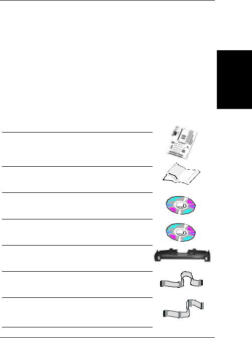
When unpacking the Motherboard, check for the following items:
uThe SY-6VBA 133 Via Apollo Pro133 AGP/PCI Motherboard
Introduction
uThis Quick Start Guide
uThe Installation CD-ROM
uSOYO 3-in-1 Bonus Pack CD-ROM (Norton AntiVirus, Ghost and Virtual Drive)
uThe CPU Retention Set
uOne IDE Device ATA 66 Flat Cable
uOne Floppy Disk Drive Flat Cable
3

SY-6VBA 133 Quick Start Guide
Introduction
SY-6VBA 133 Motherboard Layout
PS/2 KB |
PS/2 Mouse |
Connector |
Connector |
|
|
|
|
|
|
USB 1 |
USB 2 |
PRT
COM 1
COM 2
JP10 JP8 |
LED1 |
||
1 |
3 |
||
|
|||
Slot 1 |
1 |
DIMM 1 |
|
CPUFAN |
DIMM 2 |
||
® |
|
DIMM 3 |
|
|
|
||
|
|
DIMM 4 |
|
FDC |
Via ® |
11 |
|
|
|
ATX |
82C693A |
|||||||
|
|
Power |
|
|
|
|
|
|
|
|
|
|
|
|
|
|
|
|
|
|
|
|
|
|
|
|
|
|
|
|
|
|
|
|
|
|
|
|
|
|
|
|
|
|
|
|
|
|
|
|
|
|
|
|
|
|
|
|
|
|
|
|
|
|
|
|
|
|
|
|
|
|
|
|
|
|
|
JP9 |
|
|
AGP Slot |
1 |
1 |
|
IDE 2 |
IDE 1 |
||
|
PCI Slot #1 |
3V |
|
ITE 8671 |
|
|
Lithium |
|
|
I/O Chipset |
|
|
Battery JP5 |
|
|
1 IR1 5 PCI Slot #2 |
|
|
JP2 |
|
|
|
1 |
3 |
1 3
JP44 |
BIOS |
PCI Slot #3 |
|
WOL |
|
|
|
Header |
Flash |
|
Via ® |
3 |
|
||
|
|
82C596B |
|
|
|
PCI Slot #4 |
|
1 |
|
|
|
|
|
PCI Slot #5 |
|
Winbond |
|
|
ISA Slot #1 |
W83782M |
|
|
|
828AC |
ISA Slot #2 |
|
Hardware |
||
|
||
Monitoring |
|
CMOS Clear
Jumper
|
_ |
_ |
HDD |
|
LED |
||
Speaker |
+ |
||
|
|
Turbo |
|
|
|
_ |
|
|
+ |
LED |
|
JP7 |
+ |
||
|
|
|
|
Keylock |
|
|
PWRBT |
|
|
|
|
Power |
_ |
|
Reset |
LED |
+ |
|
|
1 |
|
|
|
CHAFAN
Key Features
ØSupports Intel Pentium® III processor (450600MHz), Pentium® II processor (233-450MHz) & CeleronTM processor (266-433MHz)
ØJumperless and CPU voltage Adjustable
ØSOYO COMBO Setup
ØPC98, ACPI
ØATA 33/66
ØSupports PC133 memory
ØPower-on by modem or alarm
ØSupports Wake-On-LAN (WOL)
ØSupports onboard hardware monitoring and includes Hardware Doctor ™ utility
Ø1 x 32-bit AGP slot
Ø5 x 32-bit bus mastering PCI slots
Ø2 x USB ports onboard
Ø1 x IrDA port
ØSupports multiple-boot function
ØY2K Compliant
ØSupports Power Failure Resume
4

SY-6VBA 133 Quick Start Guide
2 Installation
To avoid damage to your Motherboard, follow these simple rules while handling this equipment:
•Before handling the Motherboard, ground yourself by grasping an unpainted portion of the system's metal chassis.
•Remove the Motherboard from its anti-static packaging. Hold it by the edges and avoid touching its components.
•Check the Motherboard for damage. If any chip appears loose, press carefully to seat it firmly in its socket.
Follow the directions in this section designed to guide you through a quick and correct installation of your new SY-6VBA 133 Motherboard. For detailed information, please refer to
SY-6VBA 133 Motherboard User's guide and Technical Reference online manual included on the CD-ROM packed with your Motherboard.
PREPARATIONS
Gather and prepare all the necessary hardware equipment to complete the installation successfully:
uSlot 1 processor with built-in CPU cooling fan (boxed type)
uSDRAM module
uComputer case and chassis with adequate power supply unit
uMonitor
uPS/2 Keyboard
uPointing Device (PS/2 mouse)
uVGA Card
uSound Card (optional)
uSpeaker(s) (optional)
uDisk Drives: HDD, CD-ROM, Floppy drive …
uExternal Peripherals: Printer, Plotter, and Modem- (optional)
uInternal Peripherals: Modem and LAN cards (optional)
Hardware |
Installation |
|
|
5
Hardware |
Installation |
|
|
SY-6VBA 133 Quick Start Guide
Install the Motherboard
Follow the steps below in order to perform the installation of your new SY-6VBA133Motherboard.
Step 1. Install the CPU
 Mark your CPU Frequency: Record the working frequency of your CPU that should be clearly marked on the CPU cover.
FSB 66MHz
|
266MHz (66 x 4.0) |
|
333MHz (66 x 5.0) |
|
400MHz (66 x 6.0) |
|
|
|
300MHz (66 x 4.5) |
|
366MHz (66 x 5.5) |
|
433MHz (66 x 6.5) |
|
|
FSB 100MHz |
|
|
|
|
|
|
|
|
350MHz (100 x 3. 5) |
|
450MHz (100 x 4.5) |
|
550MHz (100 x 5.5) |
|
|
|
400MHz (100 x 4.0) |
|
500MHz (100 x 5.0) |
|
600MHz (100 x 6.0) |
|
|
|
|
|
|
|
|||
FSB 133MHz |
|
|
|
|
|
|
|
|
400MHz (133 x 3.0) |
|
533MHz (133 x 4.0) |
|
666MHz (133 x 5.0) |
|
|
|
466MHz (133 x 3.5) |
|
600MHz (133 x 4.5) |
|
733MHz (133 x 5.5) |
|
|
|
|
|
|
|
|
|
|
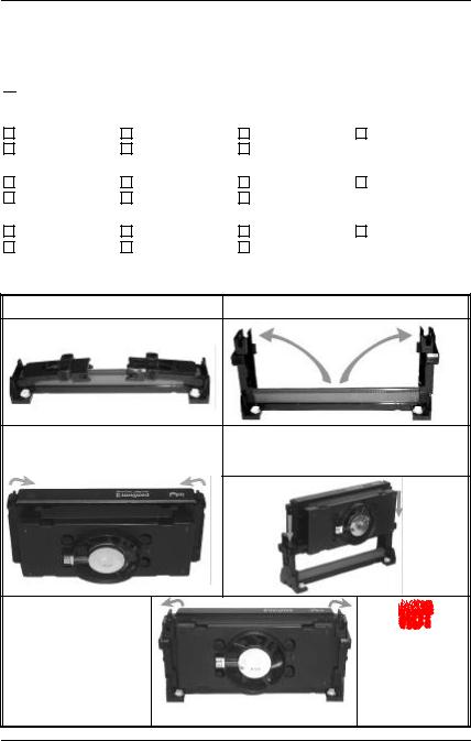
CPU Mount Procedure: To mount the processor that you have purchased separately, follow these instructions.
Retention Module |
Step 1. Open the two sides by folding them up. |
Step 2. Push the locks on top of the CPU Step 3. |
Insert the CPU into the retention |
|
inward. |
module. The CPU fits in the CPU slot in |
|
|
|
only ONE way, do not try to force it in. |
Step 4. After completely inserting the CPU, push the two locks on top of the CPU outward. Now your CPU is ready for use.
To remove the CPU, press the two notches on top of the CPU inward. Now press the two slides on the retention module down and remove the CPU.
6
SY-6VBA 133 Quick Start Guide
Note: Installing a heat sink and cooling fan on top of your CPU is necessary for proper heat dissipation. Failing to install these items may result in overheating and possible burn-out of your CPU.
Step 2. Make Connections to the Motherboard
This section tells how to connect internal peripherals and power supply to the Motherboard.
Internal peripherals include IDE devices (HDD, CD-ROM), Floppy Disk Drive, Chassis Fan, Front Panel Devices (Turbo LED, Internal Speaker, Reset Button, IDE LED, and KeyLock Switch.), Wake-On-LAN card, VGA card, Sound Card, and other devices.
For more details on how to connect internal and external peripherals to your new SY-6VBA 133 Motherboard, please refer to SY-6VBA 133 Motherboard User's Guide and Technical Reference online manual on CD-ROM.
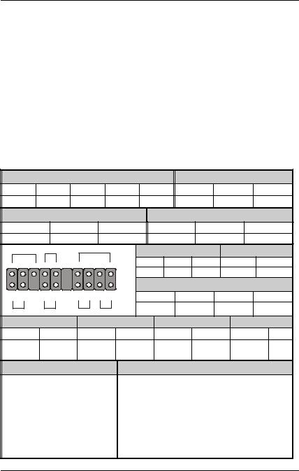
Connectors and Plug-ins
IrDA (Infrared Device Header): IR1 |
Wake-On-LAN Header: JP44 |
|||||||||||
Pin1 |
|
Pin2 |
Pin3 |
|
Pin4 |
Pin5 |
|
Pin1 |
|
Pin2 |
Pin3 |
|
VCC |
|
None |
IRRX |
|
GND |
IRTX |
5VSB |
GND |
MP-Wakeup |
|||
CPU Cooling Fan: CPUFAN |
|
Chassis Fan: CHAFAN |
|
|||||||||
Pin1 |
|
|
Pin2 |
|
Pin3 |
|
Pin1 |
Pin2 |
|
Pin3 |
||
GND |
|
|
12V |
SENSOR |
|
GND |
12V |
|
SENSOR |
|||
Power LED Key Lock |
Speaker |
_ |
|
Power LED |
|
Keylock |
||||||
+ |
_ 1 |
+ |
|
Pin1 |
Pin2 |
Pin3 |
|
Pin1 |
|
Pin2 |
||
|
|
|
|
|
|
5V |
NC |
GND |
Control Pin |
|
GND |
|
|
|
|
+ _ + _ |
|
|
Speaker |
|
|
||||
1 |
|
1 |
Pin1 |
|
Pin2 |
|
Pin3 |
Pin4 |
||||
Reset |
|
PWRBT |
Turbo LED HDD LED |
5V |
|
NC |
|
NC |
Speaker out |
|||
|
|
|
|
|
|
|
|
|||||
HDD LED |
Turbo LED |
|
PWRBT |
|
RESET |
|||||||
Pin1 |
|
Pin2 |
Pin1 |
|
Pin2 |
|
Pin1 |
Pin2 |
|
Pin1 |
Pin2 |
|
LED Anode |
LED |
LED |
|
GND |
|
Power |
GND |
|
Power Good |
GND |
||
Cathode Cathode |
|
On/Off |
|
|||||||||
|
|
|
|
|
|
|
|
|
||||
ATX Power On/Off: PWRBT |
|
ATX Power Supply: ATX PW |
|
|||||||||
Connect your power switch to this Attach the ATX Power cable to this connector. (This motherboard requires an ATX power supply, an AT power supply can NOT be used.)
Note: Please make sure the ATX power supply is able to provide at least 720mA of current on the +5VSB lead if you want to enable the advanced power management functions, like power failure resume, Power-On by keyboard, etc.
Hardware |
Installation |
|
|
7
 Loading...