

Page 1
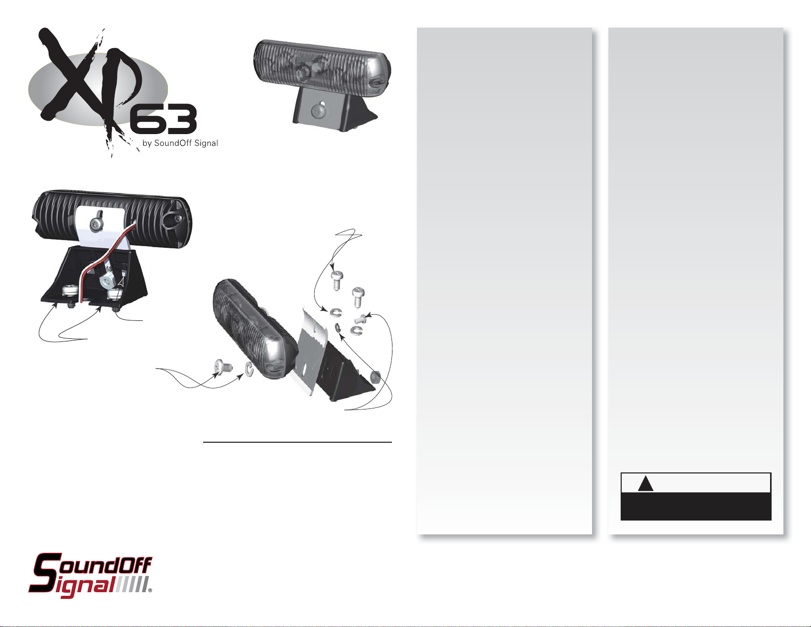
BRACKET MOUNTING
OPERATING INSTRUCTIONS
XP 63 LED LIGHT
EL6GD(x)
1/4” Screw and Lock Washers
(customer supplied)
Strain Relief
Oblong Slots
Screw and Lock Washer
for vertical adjustment
Please see reverse for
Technical Specifi cations
Screw and Lock Washer
for angular adjustment
Important Information:
• Warning devices are strictly regulated and governed by Federal, State and Municipal ordinances.
These devices shall be used ONLY on approved vehicles. It is the sole responsibility of the user of these
devices to ensure compliance.
• DO NOT install this product or route any wires in the Air Bag Deployment Zone. Refer to your vehicle
Owner’s Manual for the location of any air bag deployment zones.
• DO NOT connect this device to a strobe power supply. This product is self-contained and does not
require an external power supply.
IMPORTANT: DO NOT over tighten mounting
screws or nuts. This could cause permanent
damage to the bracket or case.
NOTE: The XP63 is shipped preassembled.
Some disassembly is required to properly
mount and align light.
1. Locate fl at or slightly arched mounting
location for XP63 Bracket.
2. When position of bracket is determined
mark location of oblong slots assuring that
light will be perpendicular to long axis of
vehicle and drill pilot holes. If wires are to
be routed to interior of vehicle a hole should
be made between the pilot holes. If the
connection is to be made inside the vehicle
this can be a small hole but if the cable is
to pass through the surface it must be large
enough to accommodate the connector.
3. Place bracket over pre-drilled pilot holes
and secure to vehicle using 2-1/4” customer
supplied screws and lock washer (preferably
stainless steel). DO NOT OVER TIGHTEN
SCREWS.
4. Make cable connections as follows:
Red-power, Black-ground. White is for ID
and pattern selection and will be taped
after selection is made. If the fi nal location
of the cable will be inaccessible, ID and
pattern selection must be made before
fi nal installation. Loose wires from the light
should be wrapped under the strain relief in
the base.
5. Light is adjusted by loosening the
vertical and angular adjustment screws
and positioning the light for optimum
performance. Make certain that light is
positioned horizontally and at the desired
height.
The XP63 comes equipped with its own
selectable 16 pattern fl asher and pattern
memory. When desired pattern is selected,
it will automatically be stored in the unit’s
memory and will come up every time the
light is turned on.
1. Connect the unit’s BLACK wire to a
good, convenient ground.
2. Connect the unit’s RED wire to one side
of a user supplied on/off switch. Connect the
other side of the switch, through a 7.5Amp
fuse, to a source of +12Vdc.
PATTERN SELECTION
1. Turn unit ON.
2. Touching and removing the WHITE wire
to ground will advance the XP63 to the
next fl ash pattern. See fl ash pattern table.
Continuing to touch and remove the WHITE
wire to ground will allow you to scroll
through the pattern list. After pattern #16
is reached the list will start over again at
pattern #1.
NOTE: The unit is equipped with fl ash
pattern memory. Once you have selected a
pattern the unit will always activate to that
pattern every time the unit is turned on. Tape
up and secure WHITE wire so that it will not
accidentally change your selected pattern.
WARNING
!
This product contains high intensity LED devices.
To prevent eye damage, DO NOT stare into the
light beam at close range.
To review our Limited Warranty Statement & Return Policy for this or any SoundOff Signal product please visit our website at www.soundoffsignal.com and select the “Warranty & Returns”
link along the left column of our home page. If you have questions regarding this product please contact Technical Services, Monday - Friday, 8 am to 5 pm at 1.800.338.7337, press #4 to
skip the automated message. Questions or comments that do not require immediate attention may be emailed to techsupport@soundoffsignal.com.
1.800.338.7337. / www.soundoffsignal.com / Thank you for trusting us with your safety!
EL6GD(x) 4.09
Page 2
XP 63 LED LIGHT
EL6GD(x)
WIRE HOOK-UP TABLE
WIRE COLOR: CONNECT TO:
RED +9-16Vdc
BLACK Ground (-)
WHITE ID/Pattern Select
Predator Sync Confi guration Instructions
IMPORTANT! A MAXIMUM OF 4 SINGLE LIGHTS
CAN BE SYNCED TOGETHER
1. Set ID#
a. Identify which pattern and sequence you want and look up ID#
settings at right.
b. Connections
i. RED: +12Vdc
ii. WHT: +12Vdc (Note: you will need to disconnect after power is
applied)
iii. BLK: Ground
c. Apply power to unit
d. Without disconnecting power from unit, disconnect WHT wire
e. Momentarily connect WHT to Ground to change ID #
i. Identify ID# by number of sequential fl ashes
ii. Possible ID#s: 1 – 4
f. Disconnect power from unit to get out of ID mode.
2. Set Pattern
a. Reapply power to units.
b. Once all Light Head ID#s are confi gured, make sure all lights are
fl ashing the same pattern
c. Connect corresponding colored wires of all units together: RED to RED,
etc.
d. Change Pattern
i. Momentarily connect WHT wires to Ground
ii. Observe pattern change on all lights
connected
e. Insulate all wires by taping with electrical tape
3. Connect Master Switch for Application
a. IMPORTANT! Ensure WHT Pattern/Sync Wires
are tied together
ALTERNATING (ID#s
DIFFERENT FOR
EACH LIGHT HEAD)
1 LIGHT
Single Light Operation: Follow the ID Selection steps and set the LED3 to
ID#1 if it is not already. NOTE: Steady Burn is produced for patterns 9 &
10 in Single Operation.
2 LIGHTS
ALTERNATING: To obtain Alternating patterns, follow the ID SELECTION
steps and set one LED3 to ID#1 and the other to ID#3. Then proceed to
the PATTERN SELECTION steps.
SIMULTANEOUS: To obtain Simultaneous patterns, follow the ID
SELECTION steps and set both LED3 lights to ID#1. Then proceed to
PATTERN SELECTION steps.
4 LIGHTS
X-Pattern: To obtain X-patterns, follow the ID SELECTION steps and set
one of the four LED3 lights to ID#1, one to ID#2, one to ID#3, and one
to ID#4. Then proceed to PATTERN SELECTION steps. NOTE: Be sure to
mount each LED3 in the correct placement based on ID#.
X-Pattern Sequence
ID#1 > ID#4 > ID#2 > ID#3
X-Pattern Light Head Placement
ID#3 ID#1
ID#4 ID#2
LIGHT HEAD ID# TABLE
SIMULTANEOUS
(ID#s DIFFERENT
FOR EACH LIGHT
HEAD)
X-PATTERN (PATTERN 15 AND 16 ONLY)
TECHNICAL SPECIFICATIONS
Overall Dimensions: 3.38”(2.88”min)”H x 5.13 W
x 2.63”D
Flash Patterns: 16 fl ash patterns
Input Voltage Range:
10 - 16 Vdc
Current Consumption: <1 amp*
# of LEDs: 6 Generation 3 LEDs
Light Sync Technology: Yes
Operating Temperature: -40º to +65º C
*Pattern Dependent
NOTE: The light CANNOT be serviced in the fi eld. Any attempt to
gain access to the unit will most likely cause permanent damage
and void its warranty.
# PATTERN SEQUENCE LT HD1 LT HD2 LT HD1 LT HD2 LT HD1 LT HD2 LT HD3 LT HD4
1 Quint ALT ID#1 ID#3 ID#1 ID#1 - - - -
2 Warp ALT ID#1 ID#3 ID#1 ID#1 - - - -
3 Inter-Cycle Flash ALT ID#1 ID#3 ID#1 ID#1 - - - -
4 Double ALT ID#1 ID#3 ID#1 ID#1 - - - -
5 Quad Flash ALT ID#1 ID#3 ID#1 ID#1 - - - -
6 3FPS ALT ID#1 ID#3 ID#1 ID#1 - - - -
7 3FPS SIM ID#1 ID#3 ID#1 ID#1 - - - -
8 Q-SWITCH VARIABLE ID#1 ID#3 N/A N/A - - - -
9 WARP, STEADY BURN STEADY BURN ID#1 ID#3 N/A N/A - - - -
10 QUAD, STEADY BURN STEADY BURN ID#1 ID#3 N/A N/A - - - -
11 E-PATTERN SINGLE FLASH ALT ID#1 ID#3 ID#1 ID#1 - - - -
12 E-PATTERN DOUBLE FLASH ALT ID#1 ID#3 ID#1 ID#1 - - - -
13 E-PATTERN SINGLE FLASH SIM ID#1 ID#3 ID#1 ID#1 - - - -
14 E-PATTERN DOUBLE FLASH SIM ID#1 ID#3 ID#1 ID#1 - - - -
15 X-WARP X N/A N/A N/A N/A ID#1 ID#1 ID#1 ID#1
16 X-DOUBLE X N/A N/A N/A N/A ID#1 ID#1 ID#1 ID#1
EL6GD(x) 4.09
 Loading...