

Page 1
UNIVERSAL UNDERCOVER PUSH-IN™
LED INSERT w/GROMMET
ELUCPS010(x) - 10-16 Vdc, 10' CABLE
ELUCPS025(x) - 10-16 Vdc, 25' CABLE
ELUCPH010(x) - 10-30 Vdc, 10' CABLE
KIT INCLUDES:
1 ea. - Assembled light head with Extreme Angle
Lens #1, in-line flasher and desired cable length
1 - EPDM Mounting Grommet
Push-In Grommet
Please see reverse for Technical
Specifications and Illustrations
Important Information:
• DO NOT cut the wires between in-line flasher and light head
• Warning devices are strictly regulated and governed by Federal, State and Municipal ordinances.
These devices shall be used ONLY on approved vehicles. It is the sole responsibility of the user of these
devices to ensure compliance.
• DO NOT install this product or route any wires in the Air Bag Deployment Zone. Refer to your vehicle
Owner’s Manual for the location of any air bag deployment zones.
• DO NOT connect this device to a strobe power supply. This product is self-contained and does not
require an external strobe power supply.
MOUNTING INSTRUCTIONS
Up to 4 LED inserts can be synchronized
for alternating or simultaneous flash
patterns using the white (SYNC) wire.
See back for SYNC Configuration
instructions.
1. Remove the reflector assembly
according to the vehicle
manufacturer’s instructions.
2. Establish a location for each
UNDERCOVER™ light head with the
following parameters:
a. Light head must have 1” clearance
from plastic/lens surfaces.
b. Light head does not interfere with
normal operation of lamp.
c. Choose a surface that is flat
as possible for good sealing when
light head is installed.
d. For greatest reflector fill and
efficiency, place the light as close
to the focal point of the reflector
as possible.
3. When removing optic lenses, use
small flat head screw driver to
carefully pry lens off assembly. When
replacing lens, do not touch LEDs or
circuit board.
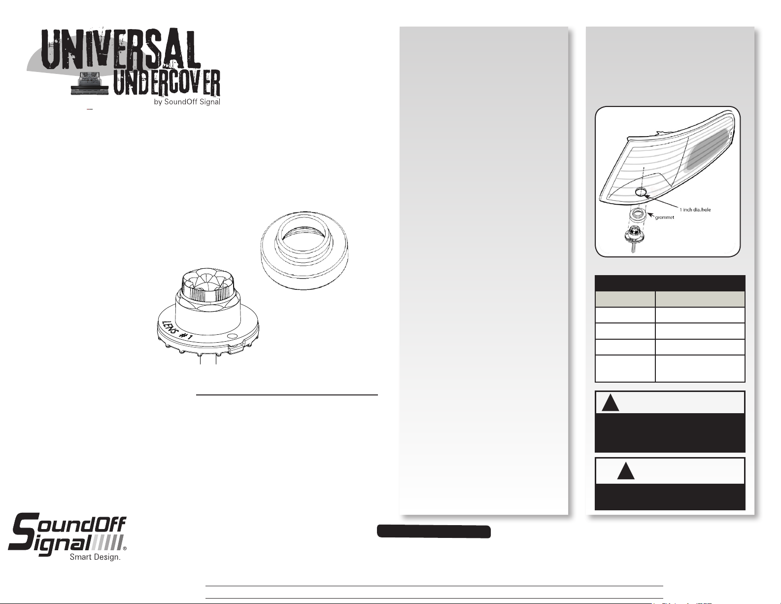
4. Using a 1” hole saw, drill a hole
in reflector housing in the location
selected in step 2.
5. Place EPDM Mounting Grommet
into hole drilled in step 4.
6. Install Undercover™ LED insert
assembly by carefully pushing it
into the grommet. Use a flat head
screw driver to lift edge of grommet
and secure light assembly inside of
grommet. See diagram.
7. Complete wire connections and
test light prior to remounting vehicle
reflector assembly
8. Re-install reflector assembly
according to vehicle manufacturer’s
instructions.
WIRE CONNECTIONS
WIRE HOOK-UP TABLE
WIRE COLOR: CONNECT TO:
RED +Vdc
BLACK Ground (-)
WHITE
GREEN
!
ARNING-HOT
W
This product must be mounted with sufficient
clearance from any plastic parts. Failure to
do so may result in permanent damage to
the housing.
!
This product contains high intensity LED
devices. To prevent eye damage, DO NOT
stare into the light beam at close range.
Pattern Select/Sync
Cruise Mode
(+Vdc)
WARNING
!
Warning devices are strictly regulated and governed by Federal, State and Municipal ordinances. These devices shall be used ONLY on approved vehicles. It is the sole responsibility of the user of these devices to ensure compliance.
1.800.338.7337 / www.soundoffsignal.com
1.
IMPORTANT INFORMATION:
To review our Limited Warranty Statement & Return Policy for this or any SoundOff Signal product, visit our website at www.soundoffsignal.com/sales-support.
If you have questions regarding this product, contact Technical Services, Monday - Friday, 8 a.m. to 5 p.m. at 1.800338.7337 (press #4 to skip the automated message).
Questions or comments that do not require immediate attention may be emailed to techservices@soundoffsigal.com.
SUPERIOR CUSTOMER RELATIONSHIPS. SMARTLY DESIGNED LIGHTING & ELECTRONIC SOLUTIONS.
ELUCP(x)0(xx)(x) 3.13
Page 2
PATTERN RESET
1. Remove power.
2. Place WHITE (sync) wire to ground.
3. With sync wire grounded, re-power RED wire.
4. Maintain for one second (light will dim).
5. Remove power and ground (pattern 1 set).
SLAVE MODE
The UNDERCOVER is capable of being activated through the use
of a user supplied flasher by putting it in slave mode.
1. Permanently connect the UNDERCOVER™ WHITE and BLACK
wire to a good, convenient ground.
2. Connect the UNDERCOVER™ RED wire, through a 3Amp fuse,
to the output of a +Vdc switching flasher.
Parts & Accessories:
PLUC2LN1E - LENS #1, Extreme Angle
PLUC2LN1V - LENS #2, Vertical Output
PLUC2LN1H - LENS #3, Horizontal Output
PLUCPGR1 - GROMMET
TECHNICAL SPECIFICATIONS
Overall Dimensions:
Flash Patterns:
Input Voltage Range:
Current Consumption:
# of LEDs:
Light Sync Technology:
1.5" n x 0.9" H
30 flash patterns
+Vdc
<1 Amp / module
6 Gen3 LEDs
Yes
Operating Temp.: -40º to +65º C
*Flash Pattern Dependent
SINGLE LIGHT HEAD SET UP AND PATTERN SELECTION
1. Disconnect WHITE wire from any connections if applicable.
2. Turn UNDERCOVER™ ON by applying power to RED.
3. Momentarily touching and removing the WHITE wire to ground will
advance the UNDERCOVER™ to the next flash pattern. Touching and
removing the WHITE wire for more than a few seconds will allow you to
change the UNDERCOVER™ to the previous pattern. See flash pattern table.
Continuing to touch and remove the WHITE wire to ground will allow you to
scroll through the pattern list. After pattern #30 is reached the list will start
over again at pattern #1.
SINGLE COLOR AND DUAL COLOR CONFIGURATIONS
Follow the ID selection steps and set the UNDERCOVER to the
following ID:
ID #1 - Split Color ID #3 - Split Color
ID #2 - Single Color ID #4 - Single Color
Single Color - Simultaneous Flash Patterns:
- Set light heads to same ID (#2 or #4).
Single Color - Alternating Flash Patterns:
- Set one light head to ID #2 and another to ID #4.
Split Color - Simultaneous Flash Patterns:
- Set light heads to the same ID (#1 or #3).
Split Color - Alternating Flash Patterns:
- Set one light head to ID #1 and another to ID #3.
MULTIPLE LIGHT HEAD SET UP AND PATTERN SELECTION
1. Set ID#
a. Connections
i. RED: +Vdc
ii. WHITE: +Vdc (Note: you will need to disconnect after power is
applied)
iii. BLK: Ground
iv. GREEN: NO CONNECTION REQUIRED FOR ID SELECTION
b. Apply power to unit
c. Without disconnecting power from unit, disconnect WHITE wire
d. Momentarily connect WHITE to Ground to change ID #
i. Identify ID# by number of sequential flashes
ii. Possible ID#s: 1 – 4
e. Disconnect Power to exit ID mode
2. Set Pattern - Must be done individually to each light prior to syncing
a. RED: +Vdc
b. BLACK: Ground
c. While light is powered, tap WHITE wire to ground to advance to the
next pattern (SEE pattern table at right)
d. Disconnect Power
3. Sync Lights
a. Once desired pattern has been selected for all light heads connect all
white wires and insulate with electrical tape.
4. Connect Master Switch for Application.
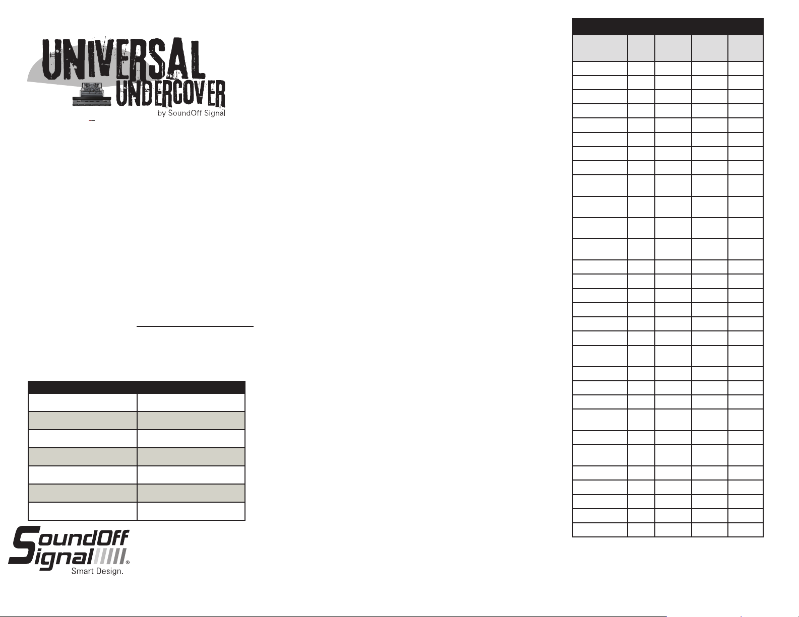
Flash Patterns
Pattern Name 1 Light
1. Quint
2. Warp
3. Inter-Cycle Flash
4. Double Flash
5. Quad Flash
6. PowerPulse™
7. RoadRunner™
8. Q-Switch™
9. RoadRunner™
Steady Burn
10. Quad Steady
Burn
11. E-Ideal Single
Flash
12. E-Ideal Double
Flash
13. Quad2 Flash
14. Double2 Flash
15. PowerRunner
16. LCR Quint
3
17. Warp
18. Ultra Warp
19. Thunder &
Lightning
20. Lite Speed
21. SuperSonic
22. LCR Lite Speed
23. SuperSonic
Ultra
24. Tempo Shift
25. Tempo Shift
Warp
26. SBE2
2
27. C
2
28. U
29. Cyclone
30. Chameleon2`
x x x 70
x x x 350
x x
x x x 70
x x x 80
x x x 180
x x x 113
x x
x x 113
x x 80
x x x 200
x x x 146
x x x 67
x x x 95
x x x
x x x
x x x
x x x 545
x x
x x x 85
x x 170
x x x
x x x
x x x
x x x
x x x 67
x x x 200
x x x 176
x x x
x x x
Alternating
2 Lights
Simultaneous
2 Lights
F.P.M.
(Flashes /
Minute)
1.800.338.7337 / www.soundoffsignal.com
2.
Maximum Light heads that can be synchronized together
is 4 without external flasher available from SoundOff Signal.
ELUCP(x)0(xx)(x) 3.13
 Loading...