

Page 1
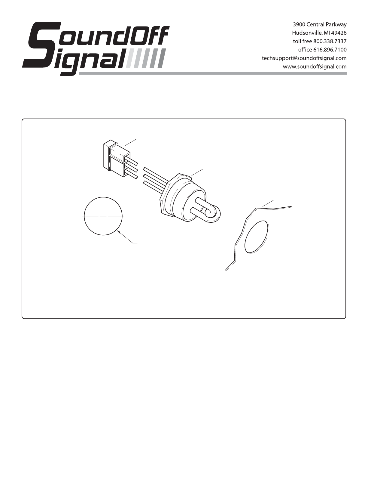
UNDERCOVERTM PUSH-IN STROBE HEAD
M
G
ETUP0(x)-P and ETUPW0(x)-P
AMP 3 POSITION
PIN CONNECTOR
123
LIGHT HEAD
ASSEMBLY
MOUNTIN
SURFACE
1" DIA.
OUNTING CONFIGURATION
WARNING
High Voltage on the surface of the glass tube. The Undercover
Strobe Light Head is a open flash tube with NO protective lens.
Proper installation is required. DO NOT TOUCH STROBE TUBE OR
THE STROBE TUBE ASSEMBLY WHEN IN OPERATION!
"COMPOSITE" AUTOMOTIVE HEADLIGHT, CORNER LIGHT
OR TAIL LIGHT INSTALLATION USING AN UNDERCOVER
STROBE LIGHT HEAD.
1. Since the Undercover Strobe Light Head will share the
same reflector as the headlight, brake light or corner light,
make sure the Undercover Push-In Strobe Tube does not
interfere with the proper operation of the currently existing
lights.
2. After taking the "Composite" reflector assembly from the
vehicle, select a surface in the rear or bottom of the "Composite" housing which is as flat as possible and cut a 1" hole. Push
the Strobe Light into the housing.
3. After selecting the best location for the Strobe Power
Supply (refer to the Power Supplies Instructions), string the 3
conductor cable (Figure A) from the Power Supply location to
the remote Strobe Light Head.
NOTE
The end of the 3 conductor cable with the
closed tip terminals (male pins) are to be
connected to the Strobe Power Supply and
the open ended terminals (female sockets)
are to connect to the Strobe Light Head
Assembly.
Make sure the strobe cable is secure along the chosen cable
routing inside the vehicle to prevent it from damage by chafing
or stretching. When used to connect Strobe Lights located in
the front of the vehicle, such as head lights, be sure to keep the
cable away from engine HOT spots.
WARNING
Strobe Tubes generate HIGH heat. Be certain
to install Undercover Tubes into a light housing
of sufficient size to dissipate the heat.
Page 2

4. Install the amp 3 socket housing onto the end of the 3
A
(
S
g:
"
C
o
conductor power cable to be connected to the Undercover
Remote Strobe Light Head Assembly, see Figure A. Connect
the cable and light first.
5. Install the amp 3 socket housing onto the end of the 3
conductor power cable to be connected to the Strobe Power
Supply, see Figure A. Connect this cable to one of the Strobe
Light outlets located on the Strobe Power Supply. Repeat the
installation instructions for the other remaining Strobe Light
Heads. Connect the Strobe Power Supply to the power source
as indicated in the instructions enclosed with the Power
Supply. Test the system.
NOTE
This testing may be performed before securing
the remote Strobe Light Head Assembly to
the mounting surface of the "Composite"
housing assembly as described in Section 2.
WARNING
OBSERVE THE COLOR OF THE WIRES TO
BE CONNECTED TO PIN NUMBER
POSITIONS when connecting the amp
connector housings to the amp pins and
sockets, see Figure A.
!
WARNING
PERSONAL INJURY HAZARD
Mounting this device in an improper location may
impair the designed safety characteristics of
the vehicle in the event of a collision.
Consult the vehicle manufacturer before
installing this or any other aftermarket device to
determine its proper mounting location.
Failure to consult and follow the vehicle
manufacturer’s mounting recommendations
may result in serious personal injury or death.
IMPORTANT CABLE INFORMATION
The cable supplied with the Undercover Strobe Head is a
shielded type with a length of shield wire exposed on each end.
On the end of the cable at the Undercover Strobe Head, cut the
shield flush with the cable jacket. On the other end of the cable,
by the Power Supply, the shield wire is to be grounded to the
vehicle chassis to reduce radio or other communication system interference. ALWAYS KEEP THIS WIRE AS SHORT AS
POSSIBLE WHEN GROUNDING. If this ground shield wire is
not to be installed, cut it flush with the cable jacket.
NOTE
SoundOff Signal Strobe Light Systems are
designed to interface with SoundOff Signal
Strobe Light Power Supplies. They are also
100% field compatible with Whelen and Tomar
Power Supplies, cables and light heads.
Detailed wiring, switching and installation
instructions are enclosed with the Strobe
Light Power Supply.
WARNING
The Strobe Power Supply is a high voltage
device, therefore DO NOT remove Strobe
Tubes or dismantle light heads while unit is
operating. ALWAYS WAIT TEN MINUTES
AFTER TUNING OFF THE POWER BEFORE
STARTING ANY TROUBLE SHOOTING.
T o Reduce EMI emissions, ONE end of the shield (drain wire)
of the extension cable connecting the output of the power
supply to the Lighthead should be connected to ground. Make
sure ONLY ONE END of the shield is tied to ground. The
other end needs to be taped or cut.
MP 3 PIN CONNECTOR HOUSING
to be mated with the AMP 3 Position
ocket on the Power Supply)
Ridge on AMP Connectors
indicate the location of Hole #1
Insert wires with Pins into the
proper locations in the Housin
123
123
RED WIRE - HOLE #1
BLACK WIRE - HOLE #2
WHITE WIRE - HOLE #3
AMP 3 SOCKET
CONNECTOR HOUSING
123
strip insulation approx. 1/8
to expose bare wire
To crimp Pins on wires,
rimp short Cradle
ver bare wire
Insert wires with Sockets
into the proper locations in
the housing:
RED WIRE - HOLE #1
BLACK WIRE - HOLE #2
WHITE WIRE - HOLE #3
123
WIRE HARNESS w/ AMP
3 PIN CONNECTOR
(attached to Undercover
Strobe Light Head)
Figure A.
Crimp tall Cradle
over wire insulation
ETUP0(x)-P 10/05
 Loading...