

Page 1
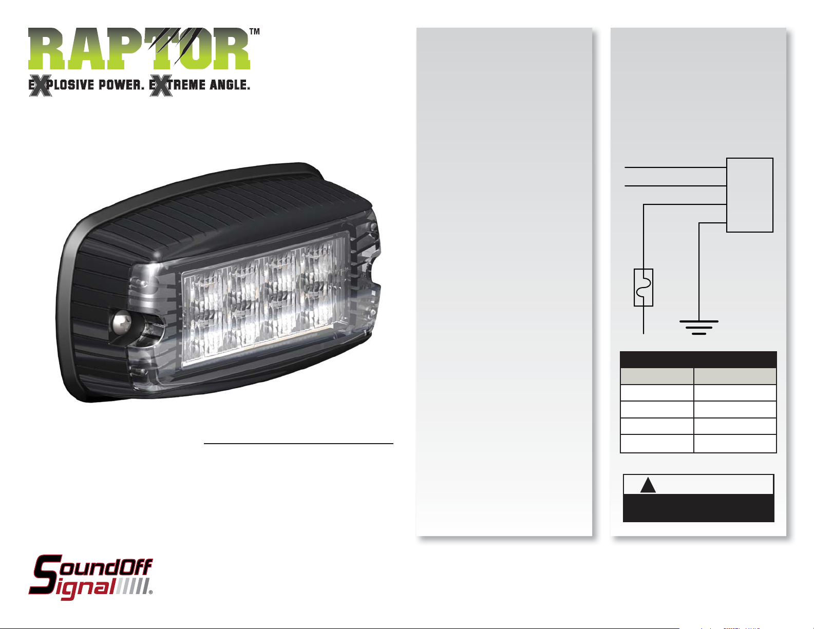
RAPTOR SINGLE SURFACE
MOUNT LIGHT
ERPT1SSMDB(x)
INSTALLATION:
1) Determine a clean, fl at location on the
vehicle to mount the Raptor Single
Surface Mount Light.
2) Using the housing as a guide mark the
centers of the outside hole positions
and drill appropriate pilot holes. The
gasket may be used if care is taken
not to stretch it. Note: the holes will
be 105.3mm on center if properly
located.
3) Drill a
4) Make electrical connections.
5) Place gasket over wires and install light
n1/2” (13mm) hole exactly
half way between the two pilot holes.
Note: this hole must be free of burrs
and sharp edges to prevent damage
to the wires.
by screwing unit to mounting surface.
CAUTION: DO NOT OVERTIGHTEN.
OPERATION:
1) Connect RED wire 10-30Vdc and
BLACK wire to ground.
2) Connect PURPLE wire to 10-30Vdc
for Cruise light.
3) To change pattern momentarily touch
WHITE wire to ground.
PURPLE
WHITE
RED
+10-30Vdc
5A
BLACK
Please see reverse for
Technical Specifi cations
Important Information:
• Warning devices are strictly regulated and governed by Federal, State and Municipal ordinances.
These devices shall be used ONLY on approved vehicles. It is the sole responsibility of the user of these
devices to ensure compliance.
• DO NOT install this product or route any wires in the Air Bag Deployment Zone. Refer to your vehicle
Owner’s Manual for the location of any air bag deployment zones.
• DO NOT connect this device to a strobe power supply. This product is self-contained and does not
require an external power supply.
To review our Limited Warranty Statement & Return Policy for this or any SoundOff Signal product please visit our website at www.soundoffsignal.com and select the “Warranty & Returns”
link along the left column of our home page. If you have questions regarding this product please contact Technical Services, Monday - Friday, 8 am to 5 pm at 1.800.338.7337, press #4 to
skip the automated message. Questions or comments that do not require immediate attention may be emailed to techsupport@soundoffsignal.com.
1.800.338.7337. / www.soundoffsignal.com / Thank you for trusting us with your safety!
WIRE HOOK-UP TABLE
WIRE COLOR: CONNECT TO:
RED +10-30Vdc
BLACK Ground (-)
WHITE ID/Pattern Select
PURPLE Cruise
WARNING
!
This product contains high intensity LED devices.
To prevent eye damage, DO NOT stare into the
light beam at close range.
ERPT1SSMDB(x) 9.09
Page 2
RAPTOR SINGLE SURFACE
MOUNT LIGHT
ERPT1SSMDB(x)
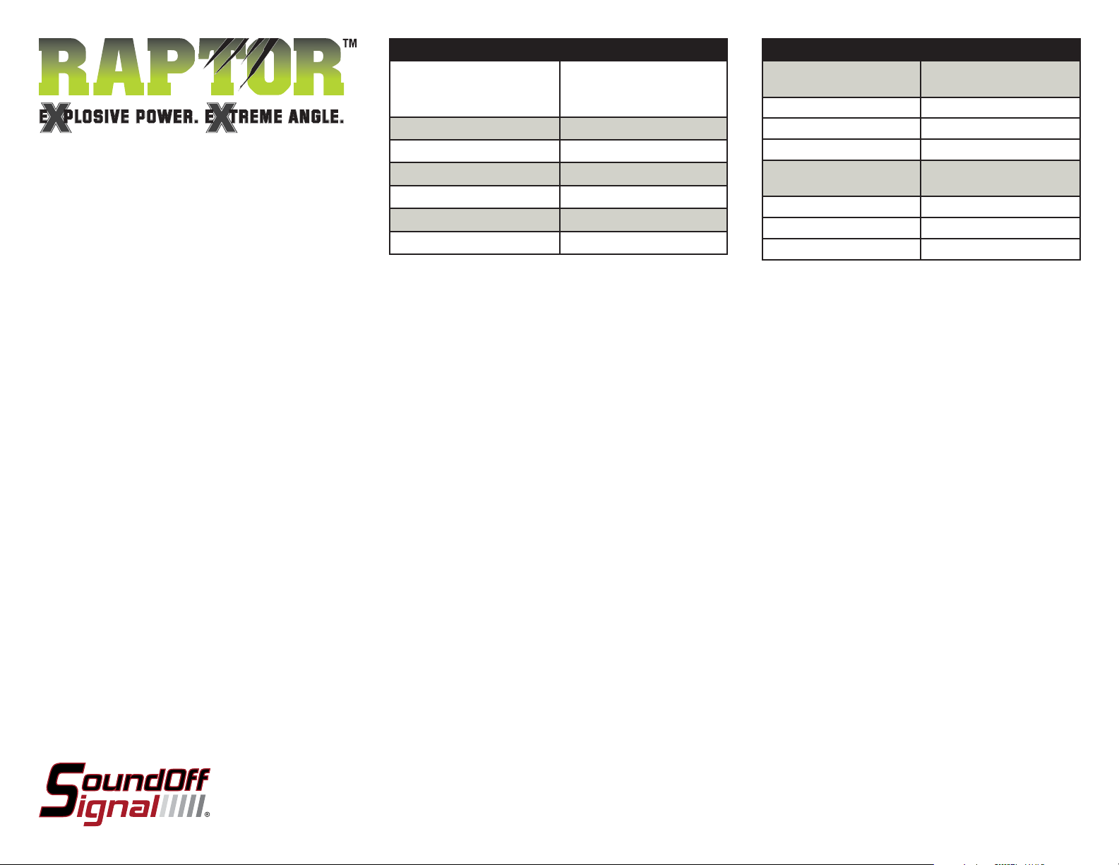
TECHNICAL SPECIFICATIONS
Overall Dimensions: 4.98”(126.6mm)L x
2.75”(70.1mm)W x
1.39”(35.3mm)D
Flash Patterns: 6 fl ash patterns
Input Voltage Range:
10 - 30 Vdc
Current Consumption: less than 2 amps
# of LEDs: 8 Generation 3 LEDs
Light Sync Technology: Yes
Operating Temperature: -40º to +65º C
Flash Patterns
FPM
Simultaneous Patterns
1. Single 125
2. Double 125
3. Triple 123
Alternating Patterns
4. Single 62
5. Double 62
6. Triple 61
(Flashes per Minute)
FPM
(Flashes per Minute)
RAPTOR Sync Confi guration Instructions
IMPORTANT! A MAXIMUM OF 4 SINGLE LIGHTS
CAN BE SYNCED TOGETHER
1. Set ID#
a. Identify which pattern and sequence you want and look up ID#
settings at right.
b. Connections
i. RED: +12Vdc
ii. WHT: +12Vdc (Note: you will need to disconnect after
power is applied)
iii. BLK: Ground
c. Apply power to unit
d. Without disconnecting power from unit, disconnect WHT
wire
e. Momentarily connect WHT to Ground to change ID #
i. Identify ID# by number of sequential fl ashes
ii. Possible ID#s: 1 – 4
f. Disconnect power from unit to get out of ID mode.
2. Set Pattern
a. Reapply power to units.
b. Once all Light Head ID#s are confi gured, make sure all
lights are fl ashing the same pattern
c. Connect corresponding colored wires of all units together:
RED to RED, etc.
d. Change Pattern
i. Momentarily connect WHT wires to Ground
ii. Observe pattern change on all lights connected
e. Insulate all wires by taping with electrical tape
3. Connect Master Switch for Application
a. IMPORTANT! Ensure WHT Pattern/Sync Wires are tied
together
1 LIGHT
Single Light Operation: Follow the ID Selection steps and set the
RAPTOR to ID#1 if it is not already. NOTE: Use Patterns 1-3.
2 LIGHTS
ALTERNATING: To obtain Alternating patterns, follow the ID
SELECTION steps and set one RAPTOR to ID#1 and the other to
ID#3. Then proceed to the PATTERN SELECTION steps. NOTE: Use
Patterns 4-6.
SIMULTANEOUS: To obtain Simultaneous patterns, follow the ID
SELECTION steps and set both RAPTOR lights to ID#1. Then proceed
to PATTERN SELECTION steps. NOTE: Use Patterns 1-3.
ERPT1SSMDB(x) 9.09
 Loading...