

Page 1
WARNING
!
This product contains high intensity LED
devices. To prevent eye damage, DO NOT
stare into light beam at close range.
IMPORTANT: DO NOT connect
this device to a strobe power supply
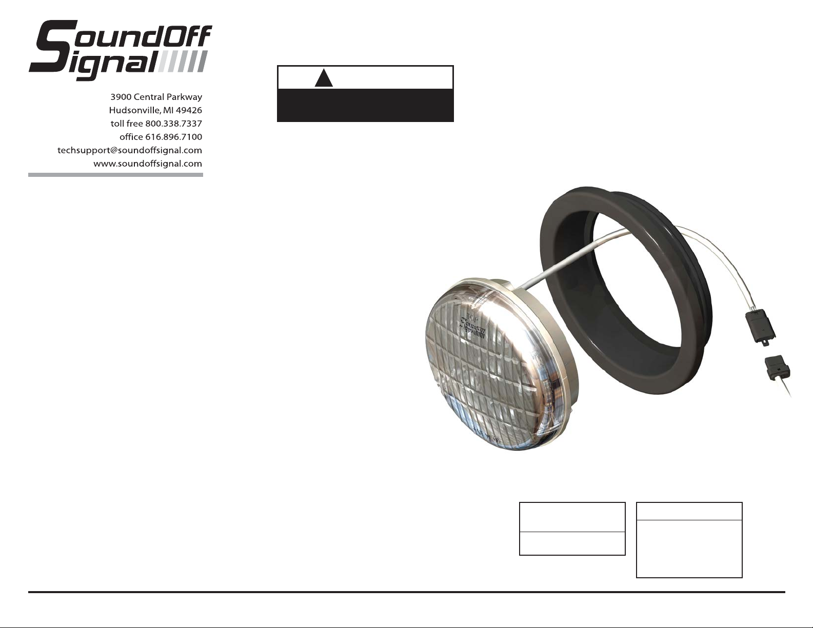
R4 SERIES LED LIGHT
ERDREBZ3(xx)
WARNING: Warning devices are strictly
regulated and governed by Federal, State, and
Municipal ordinances. These devices shall be
used ONLY on approved vehicles. It is the sole
responsibility of the user of these devices to
ensure compliance.
GROMMET MOUNTING
1. Cut a 4-1/2” hole in vehicle if needed.
2. Push Rubber Grommet into hole until it
seats
3. Feed wires through hole and connect the
wires to user supplied switching unit inside
vehicle.
4. Push the light into grommet until it seats.
The word “Top” must be positioned at the
top of the light.
OPERATING INSTRUCTIONS
The R4 Series LED light comes equipped
with its own selectable 16 pattern flasher
or it can be put into slave mode and driven
through an external flasher.
1. Connect the BLACK wire to a good,
convenient ground.
2. Connect the RED wire to one side of user
supplied on/off switch. Connect the other
side of the switch, through a 5 Amp fuse,
to a source of +10-16Vdc.
PATTERN SELECTION
1. Turn light ON.
2. Touching and removing the WHITE wire to
ground will advance the light to the next
flash pattern. See flash pattern table.
Continuing to touch and remove the
WHITE wire to ground will allow you to
scroll through the pattern list. After pattern
#16 is reached the list will start over again
at pattern #1.
Note: The R4 Series LED Light is equipped
with a flash pattern memory. Once you
have selected a pattern, the light will
always activate to that pattern every time
the unit is turned on. Tape and secure
WHITE wire so that it will not accidentally
change your selected pattern.
SLAVE MODE
The R4 Series Light is capable of being
activated through the use of a user
supplied flasher by putting it in slave
mode.
1. Permanently connect the WHITE
to a good, convenient ground.
2. Connect the RED wire, through a
5 Amp fuse, to the output of a
+10-16Vdc switching flasher.
CURRENT DRAW AT
12.8Vdc
1 Amp (All configs.)
WIRE HOOK-UP T ABLE
Wire Color
Connect to:
Red +9-16Vdc
Black Ground (-)
White ID/Pattern Select
E36REBB3(XX) 11.06
Page 2
R4 SERIES LED LIGHT
ERDREBZ3(xx)
R4 Series Sync Configuration Instructions
1. Set ID#
a. Identify which pattern and sequence you want and look up ID#s on table.
b. Connections
i. RED: +12Vdc
ii. WHT: +12Vdc (Note: you will need to disconnect after power is applied)
iii. BLK: Ground
c. Apply power to unit
d. Without disconnecting power from unit, disconnect WHT wire
e. Momentarily connect WHT to Ground to change ID #
i. Identify ID# by number of sequential flashes
ii. Possible ID#s: 1 – 4
f. Disconnect power from unit to get out of ID mode.
2. Set Pattern
a. Reapply power to units.
b. Once all Light Head ID#s are configured, make sure all lights are flashing the same
pattern
c. Connect corresponding colored wires of all units together: RED to RED, etc.
d. Change Pattern
i. Momentarily connect WHT wires to Ground
ii. Observe pattern change on all lights connected
e. Insulate all wires by taping with electrical tape
3. Connect Master Switch for Application
a. IMPORTANT! Ensure WHT Pattern/Sync Wires are tied together
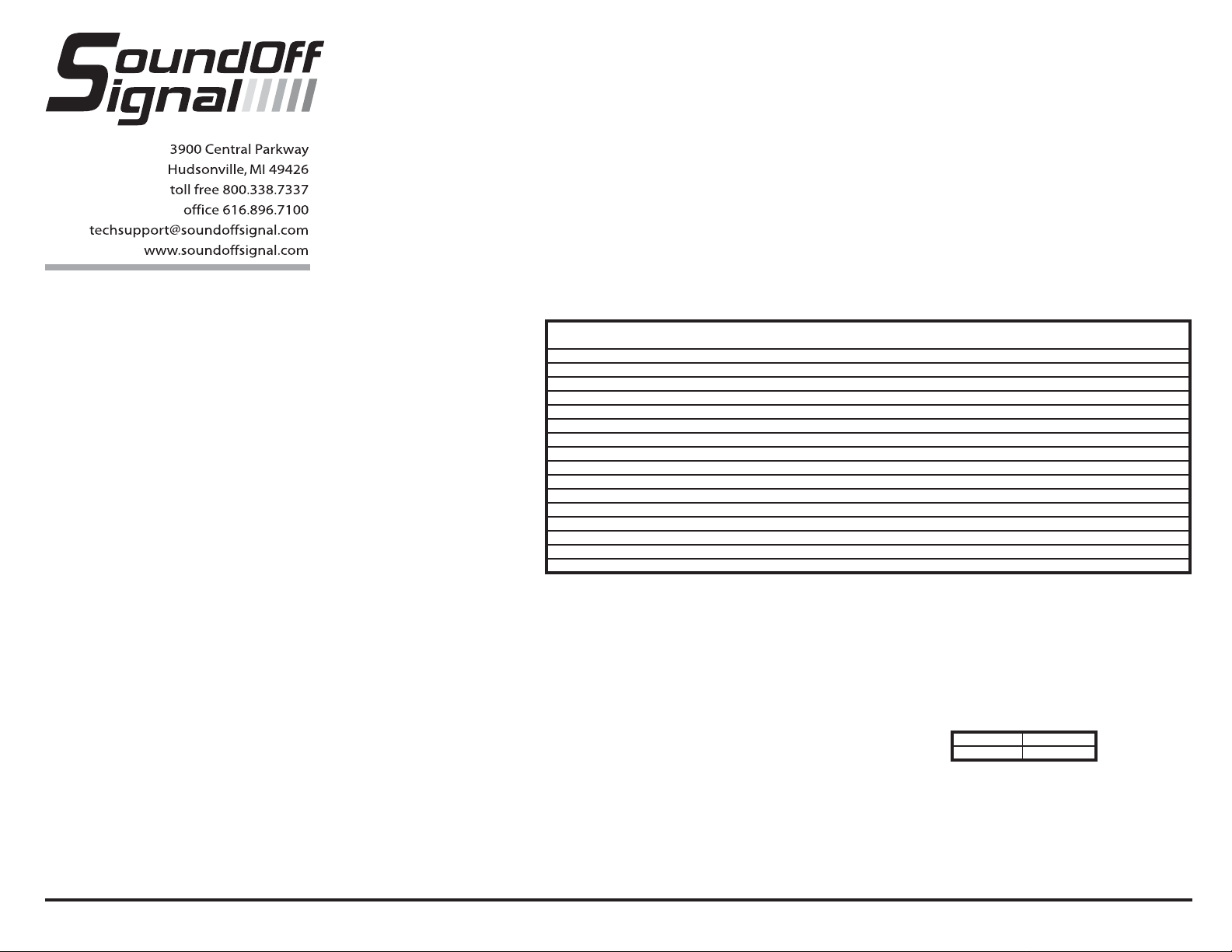
FLASH PATTERNS for
R4 Series LED Light (fpm=flashes/minute)
Alternating Simultaneous X-Pattern Flashes /
# Pattern Name 1 Light 2 Lights 2 Lights 4 Lights Minute
1 Quint X X X - 70
2 Warp X X X - 350
3 Inter-Cycle Flash X X - 4 Double X X X - 70
5 Quad Flash X X X - 80
6 3 FPS X X X - 180
7 3 FPS X X X - 180
8 Q-Switch X X - -
9 Warp, Steady Burn X X - - 350
10 Quad, Steady Burn X X - - 80
11 E-Pattern Single Flash X X X - 230
12 E-Pattern Double Flash X X X - 125
13 E-Pattern Single Flash X X X - 230
14 E-Pattern Double Flash X X X - 155
15 X-Warp - - - X 350
16 X-Double - - - X 70
1LIGHT
Single Light Operation: Follow the ID Selection steps and set the light to ID#1 if it is not already. NOTE: Steady Burn is produced for
patterns 9 & 10 in Single Operation.
2 LIGHTS
X-Pattern Sequence
ID#1 > ID#4 > ID#2 > ID#3
X-Pattern Light Head Placement
ALTERNATING: To obtain Alternating patterns, follow the ID SELECTION steps and set one light to ID#1 and the other to ID#3. Then
proceed to the PATTERN SELECTION steps.
SIMULTANEOUS: To obtain Simultaneous patterns, follow the ID SELECTION steps and set both lights to ID#1. Then proceed to PATTERN
SELECTION steps.
4 LIGHTS
X-Pattern: To obtain X-patterns, follow the ID SELECTION steps and set one of the four lights to ID#1, one to ID#2, one to ID#3, and one to
ID#4. Then proceed to PATTERN SELECTION steps. NOTE: Be sure to mount each light in the correct placement based on ID#.
ID#4 ID#2
ID#3 ID#1
E36REBB3(XX) 11.06
 Loading...