

Page 1

QUANTUM™ Q450 POWER SUPPLY
WARNING: High Voltage! Please wait 5 minutes after shutting this unit off
before attempting service. Warranty void if seal is broken.
QUANTUM
MODEL #ETQ450
4 HEAD
50 WATT
MULTI-FLASH
3 POSITION SOCKET
LIGHT HEAD CONNECTION
FRONT MOUNTING PLATE
(ALSO ON BACK)
10 AMP FUSE
(FOR PROTECTION)
3 POSITION
SOCKET POWER INPUT
(ETQ450)
Included with the Quantum Q450 power supply:
1. One wire harness for Power Input Socket. This consists of
one AMP 3 pin connector with three wires: red(+), black (-) and
violet (high/low switching).
2. One wire harness for Control Socket. This consists of
one AMP 3 pin connector with three wires: yellow, green and
blue.
WARNING
This power supply is NOT waterproof.
The Model Q450 Strobe Power supply is a four head unit which
must be mounted in an area protected from the weather and
water.
MODEL Q450 STROBE POWER SUPPLY
SPECIFICATIONS
V oltage 10-30 Vdc
Current 4.3 Amps @ 12.8 Vdc
Power 50 Watts
Fuse 10 Amp
Number of Heads 4, 2 Alternating w/ 2
Figure A
INSTALLATION
1. First, install the Q450 Strobe Power Supply in a protected
location using the power supply itself as a template. THE
POWER SUPPL Y MUST BE MOUNTED TO A MET AL SURFACE. Make sure all 3 position socket connectors are easily
accessible. The unit is mounted using the 4 mounting holes
on a 6" x 2.5" rectangle (matches exactly the Whelen UPS
Series).
2. Install the strobe light heads in the preferred locations.
3. String the 3-conductor cables between the lights and the
power supply . Make sure the cable is secure along the chosen routing inside the vehicle to prevent it from damage by
chafing or binding. Be sure to keep the cable away from engine hot spots.
MALE AMP CONNECTOR
(to be mated with the AMP output
socket on the Power Supply)
Insert wires with female pins into
the proper locations in the female
AMP connector:
RED WIRE - HOLE #1
BLACK WIRE - HOLE #2
WHITE WIRE - HOLE #3
Figure B
Insert wires with male pins into
the proper locations in the male
AMP connector:
RED WIRE - HOLE #1
BLACK WIRE - HOLE #2
WHITE WIRE - HOLE #3
FEMALE AMP CONNECTOR
AMP WIRE HARNESS
(attached to Strobe Light Head)
Page 2
NOTE
123
RED WIRE (+) in Hole #1
BLACK WIRE (-) in Hole #2
VIOLET WIRE (HIGH/LOW) in Hole #3
2 WIRE POWER-INPUT
HARNESS ASSEMBLY
8 INCH HIGH/LOW WIRE
ASSEMBLY WITH AMP PIN
FACTORY CRIMPED ON
When routing the cable, make sure the end with the
closed tip terminals (male pins) is toward the power
supply and the end with the open tip terminals (female
pins) is toward the light head.
The Flash Control Harness assembly must be connected to
the control socket located on the Q450 Strobe Light power
supply, see Figure E and Figure A. Use 18 gauge wire to
extend the control harness wires to a customer supplied switch
to complete the installation.
4. Insert the pins on each end of the conductor cables into
the AMP connectors. Each end of these cables has a factory
crimped pin on each of the three wires, see Figure B.
NOTE
It is important to follow the correct color code when
inserting the pins into the AMP connectors.
5. Connect the cables to the strobe light heads.
6. Next, plug the other end of the cable into the light head
output socket on the strobe power supply , see Figure A. The
location of the connector for each light head attached to the
unit will be determined by the flash pattern selected (see figure E).
7. Plug the Flash Control Wire Harness assembly into the
Flash Control Input Socket on the strobe power supply . Connect the wires from Flash Control Wire Harness assembly to
the switch control panel (see “Flash Control Wire Harness
Assembly” section).
8. Plug the Power Wire Harness assembly into the Power
Input Socket. Connect the strobe power supply to the power
source to complete the installation (see “Power Wire Harness
Assembly” section).
POWER WIRE HARNESS ASSEMBLY
The power wire harness is connected to the power input socket
located on the Q450 Strobe Power supply, see Figure A and
Figure E. The power wire harness assembly consists of red
and black wires (see Figure D) that power the strobe power
supply (see Figure A) and a violet wire that controls the day/
night (high/low) intensity feature of the power supply (see Figure G).
The high/low intensity feature allows the strobe lights of the
system to be switched into low power or reduced intensity.
This feature is useful for night time use. When the violet wire
is powered with (+) 12 volts, the power supply is switched to
low intensity. When power is removed, the power supply
switches to high intensity mode. If the high/low feature is not
wanted, simply do not install the violet wire, see Table for
exception.
FLASH CONTROL WIRE HARNESS ASSEMBLY
The Flash Control Wire Harness assembly consists of an AMP
3 pin connector with 3 wires: green, blue and yellow (see Figure C or Figure E). The green wire controls the strobe light
outlets 1 and 4. The blue wire controls the strobe light outlets
2 and 3. For a standard Quad flash installation, the yellow
wire is not used and can be removed.
NOTE
If the special flash options (WarpFlash™, Quint,
Double) are to be used, the yellow wire is needed and
the blue and green wires take on different functions,
see “Special Mode” section.
RIDGE
(indicates location of hole #1)
YELLOW WIRE - HOLE #1
AMP 3 PIN
CONNECTOR HOUSING
Figure C. Flash Control Wire Harness
GREEN WIRE - HOLE #2
BLUE WIRE - HOLE #3
Figure D. Power Wire Harness
Use 18 gauge wire to extend the red and black wires and the
violet high/low control wire (if used) to a customer supplied
control switching system, see Figures F and G.
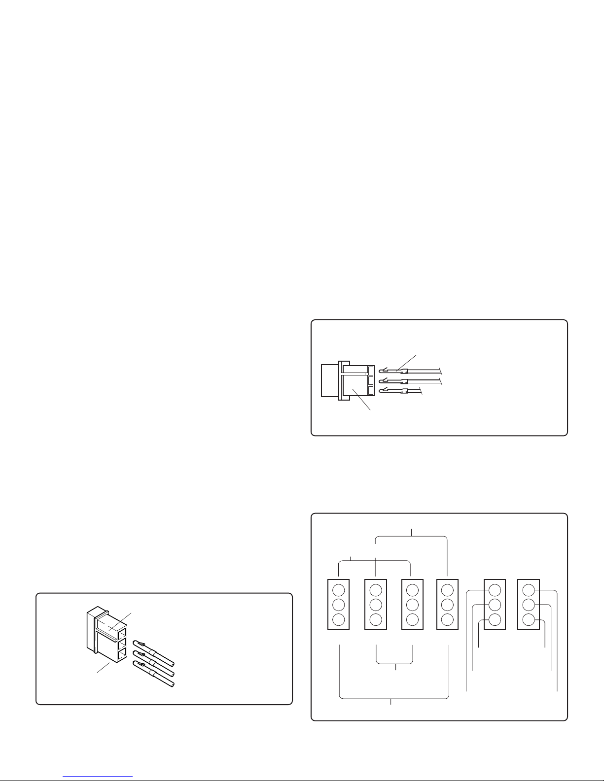
SIMULTANEOUS FLASH
SIMULTANEOUS FLASH
CONTROL
123
123
123
123
POWER
123
1234
VIOLET
BLACK (-)
RED (+)
ALTERNATING FLASH
ALTERNATING FLASH
Figure E
BLUE (+)
GREEN (+)
YELLOW (+)
Page 3

SWITCH CONTROL OPTIONS
Figures F and G show some of the standard switch control
options that can be easily wired to complete a Strobe Light
system.
Figure F , ALL HEADS ON HIGH POWER ONLY . This wiring
diagram shows an on/off control system that powers all four
heads.
Figure H shows how any flash option could be installed depending on which control wire(s) are attached to the switch.
All high power flash patterns, with the exception of patter #16,
can be easily selected with a single binary switch encoded
rotary switch (
SoundOff Signal part #PEPBE2).
Figure G, ALL HEADS ON WITH HIGH AND LOW POWER
CONTROL. This wiring diagram shows a high/low control system that powers all four heads.
YELLOW
(remove)
GREEN (+)
Attach Y ellow
wire for
WarpFlash
CONTROL
BLUE (+)
TM
SPST ON/OFF SWITCH
POWER
123
(Rear View)
RED (+)
BLACK (-)
VIOLET
(remove)
15 AMP FUSE
+12 Vdc
Figure F
Standard Quad Flash All Outlets High/Off Switching
YELLOW
(remove)
CONTROL
BLUE (+)
GREEN (+)
POWER
123
RED (+)
BLACK (-)
VIOLET
(High/Low)
DIRECT CONNECTION
OPTIONAL CONNECTION
YELLOW (+)
CONTROL
GREEN (+)
BLUE (+)
SPST ON/OFF SWITCH
POWER
123
(Rear View)
RED (+)
BLACK (-)
VIOLET
(Remove except for
Double Flash)
15 AMP FUSE
+12 Vdc
Figure H
Special Pattern Options High/Off Switching
T o Reduce EMI emissions, ONE end of the shield (drain wire)
of the extension cable connecting the output of the power
supply to the Lighthead should be connected to ground. Make
sure ONLY ONE END of the shield is tied to ground. The
other end needs to be taped or cut.
!
WARNING
PERSONAL INJURY HAZARD
Mounting this device in an improper location may
impair the designed safety characteristics of
the vehicle in the event of a collision.
Consult the vehicle manufacturer before
installing this or any other aftermarket device to
determine its proper mounting location.
Failure to consult and follow the vehicle
manufacturer’s mounting recommendations
may result in serious personal injury or death.
Attach Y ellow
wire for
WarpFlash
TM
SPST ON/OFF SWITCHES
(Rear View)
15 AMP FUSE
Figure G
Standard Quad Flash All Outlets With High/Low Switching
+12 Vdc
SoundOff Signal warranties the ETQ450 Quantumtm Strobe Power Supply for 2 (two)
WARRANTY
full years from date of purchase, to the original purchaser, against any manufactured
defects or workmanship. This warranty applies only to units installed according to
manufacturer's installation instructions and operated within the units specifications.
Warranty is void if the unit was installed incorrectly or maliciously damaged.
All warranty claims must be accompanied by a dated proof of purchase.
SoundOff Signal retains the right to be the sole mediator of what constitutes defects
in performance or manufacturing.
Page 4

Function
All Heads OFF
Quad Flash Heads 2 & 3 High Power
Quad Flash Heads 1 & 4 High Power
Quad Flash All Heads High Power
WarpFlash™ Heads 2 & 3 High Power
WarpFlash™ Heads 1 & 4 High Power
WarpFlash™ All Heads High Power
Quint Flash All Heads High Power
All Heads OFF
Quad Flash Heads 2 & 3 Low Power
Quad Flash Heads 1 & 4 Low Power
Quad Flash All Heads Low Power
WarpFlash™ Heads 2 & 3 Low Power
WarpFlash™ Heads 1 & 4 Low Power
WarpFlash™ All Heads Low Power
Double Flash All Heads High Power
Violet
SPECIAL MODE
Blue
Green
Yellow
0
NOTE: Entries 1-4 & 9-12 in the table are the industry standard functions.
0
0
0
0
0
0
0
1
1
1
1
1
1
1
1
0
1
0
1
0
0
1
1
0
1
0
1
0
0
1
1
0
0
1
1
0
1
0
1
0
0
1
1
0
1
0
1
0
0
0
0
1
1
1
1
0
0
0
0
1
1
1
1
1
2
3
Pattern
To select any one of the different flash modes, simply connect the Y ellow, Violet, Blue and Green wires to a switch in the following
combinations to receive power when ON: (“1” = 12V and a “0” = no connection or ground).
4
5
6
7
8
9
10
11
12
13
14
15
16
ETQ450 3/05
 Loading...