

Page 1
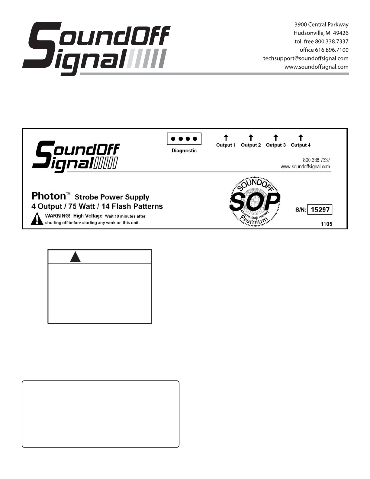
PHOTON STROBE POWER SUPPLY
MODEL # : ETPN475 / ETPN475WP
INSTALLATION
!
WARNING
PERSONAL INJURY HAZARD
Mounting this device in an improper location may
impair the designed safety characteristics of
the vehicle in the event of a collision.
Consult the vehicle manufacturer before
installing this or any other aftermarket device to
determine its proper mounting location.
Failure to consult and follow the vehicle
manufacturer’s mounting recommendations
may result in serious personal injury or death.
WARNING
High V oltage! Please wait 5 minutes after shutting
this unit OFF before attempting service. Warranty
void if seal is broken.
STROBE POWER SUPPLY
SPECIFICATIONS
Vo ltage 8-30 Vdc
Current 5.8 Amps @ 12.8 Vdc
Power 75 Watts
Fuse 15 Amp
Number of Heads 4
1. First, install the Strobe Power Supply in a protected location using the power supply itself as a template. THE POWER
SUPPLY MUST BE MOUNTED TO A METAL SURFACE.
Make sure all connectors are easily accessible.
2. Install the strobe light heads in the preferred locations.
3. String the 3 conductor cables between the lights and the
power supply . Make sure the cable is secure along the chosen routing inside the vehicle to prevent it from damage by
chafing or binding. Be sure to keep the cable away from engine hot spots.
WARNING
Strobe tube cables with 500V insulation resistance
must be used. Automotive cable is not suitable and
should not be used.
NOTE
When routing the cable, make sure the end with the
closed tip terminals (male pins) is toward the power
supply and the end with the open tip terminals (female
pins) is toward the light head.
4. Insert the pins on each end of the cables into the connectors. Each end of these cables has a factory crimped pin on
each of the three wires, see Figure A.
Page 2

MALE AMP CONNECTOR
(to be mated with the AMP output
socket on the Power Supply)
Insert wires with female pins into
the proper locations in the female
AMP connector:
RED WIRE - HOLE #1
BLACK WIRE - HOLE #2
WHITE WIRE - HOLE #3
ETPN475 - Amp Connectors
Insert wires with male pins into
the proper locations in the male
AMP connector:
RED WIRE - HOLE #1
BLACK WIRE - HOLE #2
WHITE WIRE - HOLE #3
FEMALE AMP CONNECTOR
AMP WIRE HARNESS
(attached to Strobe Light Head)
Insert wires with male pins into
the proper locations in the male
WP connector:
RED WIRE - HOLE A
BLACK WIRE - HOLE B
WHITE WIRE - HOLE C
the strobe lights to be switched into low power or reduced
intensity . This feature is useful for night time use. When the
grey(brown) wire is powered, the power supply is switched to
low intensity . When the power is removed, the power supply
switches to high intensity mode. Use 18 gauge wire to extend the flash control wires to a customer supplied switch as
shown in Figures B, C and D.
8. Connect the red wire to the positive (+) side of the battery
making sure to place a customer supplied 15 Amp fuse at the
battery . Connect the black wire to the negative (-) side of the
battery or to the vehicle chassis.
NOTE
T o extend the power (+) and ground (-) wires, use the
following as a guide.
1 to 10 ft. use 16 AWG wire
10 to 20 ft. use 14 AWG wire
20 to 30 ft. use 12 AWG wire
30 to 50 ft. use 10 AWG wire
Figures B, C and D show some of the standard switch control
options that can be easily wired to complete a Strobe Light
System.
Figure B shows a high/off control system that quad flashes
all heads.
Figure C shows a high/low control system that quad flashes
all heads.
Insert wires with female pins into
the proper locations in the female
WP connector:
RED WIRE - HOLE A
BLACK WIRE - HOLE B
WHITE WIRE - HOLE C
ETPN475WP - WP Connectors
Figure A.
NOTE
It is important to follow the correct color code when
inserting the pins into the connectors.
5. Connect the cables to the strobe light heads.
6. Next, plug the other end of the cable into the Light Head
Output Socket on the Strobe Power Supply.
7. Using Figure E, select a flash pattern and determine which
flash control wires will need to be used. The grey(brown) wire
controls the day/night (high/low) intensity feature of the power
supply, see Figure C. The high/low intensity feature allows
Figure D shows how any flash option could be installed depending on which flash control wire(s) are attached to the
switch.
DIRECT CONNECTION
OPTIONAL CONNECTION
STROBE POWER
SUPPL Y
BLUE
RED (+)
SPST ON/OFF SWITCH
Quad Flash All Heads High/Off Switching
GREEN
(REAR VIEW)
15 AMP
FUSE
Figure B.
BLACK (-)
(+) 8-30 VDC
Page 3

STROBE POWER SUPPL Y
OPTIONAL STROBE POWER SUPPLY
DIAGNOSTIC PANEL
FOR USE WITH DIAGNOSTIC EQUIPPED POWER SUPPLIES ONLY
BLUE
GREEN
RED (+)
TWO SPST ON/OFF SWITCHES
(REAR VIEW)
GREY
(BROWN)
15 AMP
FUSE
BLACK (-)
(+) 8-30 VDC
Figure C.
Quad Flash All Heads High/Low Switching
DIRECT CONNECTION
OPTIONAL CONNECTION
STROBE POWER SUPPL Y
132
4
LOW
INTENSITY
4 - HEAD
PEDIPNL4/
PEDIPNL4WP
132
4
56
LOW
INTENSITY
6 - HEAD
PEDIPNL6/
PEDIPNL6WP
132
4
56
78
LOW
INTENSITY
8 - HEAD
PEDIPNL8
OUNTING OPTIONS:
. Display will snap into any existing
panel with a 22.5mm x 40mm hole.
TABS
. Remove tabs from the back of
display and adhere to mounting
surface using double sided tape.
NSTALLATION:
lug the RJ11 end of the cable into the Diagnostic Display.
oute the other end of the cable to the Power Supply and
onnect the 4-pin Amp Connector.
PERATION:
ach numbered LED will flash with the corresponding
umbered Strobe Tube showing everything is operational. If
n LED light stay ON, instead of flashing, there is a problem
ith that particular Strobe Tube or Strobe Cable. Low
ntensity LED will indicate when the Power Supply is low
ower.
BLUE
GREEN
RED (+)
SPST ON/OFF SWITCH
(REAR VIEW)
GREY
(BROWN)
YELLOW
15 AMP
FUSE
BLACK (-)
(+) 8-30 VDC
Figure D.
Special Pattern Options On/Off Switching
o Reduce EMI emissions, ONE end of the shield (drain wire)
f the extension cable connecting the output of the power
upply to the Lighthead should be connected to ground.
ake sure ONLY ONE END of the shield is tied to ground.
he other end needs to be taped or cut.
WARRANTY
SoundOff Signal warranties the Photon Strobe Power Supply
for five (5) years from the date of purchase to the original purchaser against any manufactured defects or workmanship.
This warranty is a 100% replacement value warranty . It applies only to units installed according to manufacturer’s installation instructions and operated within the units specifications.
Warranty is void if the unit was installed incorrectly or maliciously damaged.
All warranty claims must be accompanied by a dated proof of
purchase.
SoundOff Signal retains the right to be the sole mediator of
what constitutes defects in performance or manufacturing.
Page 4

-
-
140 FPM
140 FPM
Flash Rate
140 FPM
Function
Quad Flash Heads 2 Alt. 3 High Power
Quad Flash Heads 1 Alt. 4 High Power
Quad Flash Heads 1,3 Alt. 2,4 High Power
Inter-Cycle™ Flash Heads 2 Alt. 3 High Power
Inter-Cycle™ Flash Heads 1, 3 Alt. 2, 4 High Power
140 FPM
140 FPM
140 FPM
Inter-Cycle™ Flash Heads 1 Alt. 4 High Power
Quint Flash Heads 1,3 Alt. 2,4 High Power
Quad Flash Heads 2 Alt. 3 Low Power
Quad Flash Heads 1 Alt. 4 Low Power
-
-
-
140 FPM
Quad Flash Heads 1,3 Alt. 2,4 Low Power
Inter-Cycle™ Flash Heads 2 Alt. 3 Low Power
Inter-Cycle™ Flash Heads 1, 3 Alt. 2, 4 Low Power
Inter-Cycle™ Flash Heads 1 Alt. 4 Low Power
700 FPM
NOTE: All other Matrix’s are OFF’s.
Warp Flash Heads 1,3 Alt. 2,4 High Power
Blue
POWER
Green
POWER
POWER
POWER
Yellow
Grey
1
2
3
Pattern
FIGURE E. To select any one of the different flash modes, simply connect the Blue, Green, Yellow, and Grey wires to a switch in the
following combinations. Connect the wires marked “POWER” to (+) 10-30 Vdc and remove the unused wires or connect them to (-) ground.
POWER
POWER
POWER
4
5
POWER
POWER
POWER
POWER
POWER
6
7
POWER
POWER
POWER
POWER
8
9
POWER
POWER
POWER
POWER
POWER
11
10
POWER
POWER
POWER
POWER
POWER
POWER
13
12
POWER
POWER
POWER
POWER
14
ETPN475-ETPN475WP 9/06
 Loading...