

Soundoff Signal nROADS ENRBCSHM 1 Z, nROADS ENRBCSHC 1 Z Series, nROADS ENRBCSLC 1 Z Series, nROADS ENRBCSLM 1 Z Series Series Manual
Page 1

HIGH DOME BEACON
HIGH DOME
MAGNET MOUNT - ENRBCSHM(x)1(x)Z(xxx)
COMBO: FLAT/PIPE MOUNT - ENRBCSHC(x)1(x)Z(xxx)
LOW DOME
MAGNET MOUNT - ENRBCSLM(x)1(x)Z(xx)
COMBO: FLAT/PIPE MOUNT - ENRBCSLC(x)1(x)Z(xxx)
Distributed by
TECHNICAL SPECIFICATIONS
Dimensions:
Input Voltage: 9-17.5Vdc
Standby Current:
<0.0001 Amps after 10 seconds of no
active control inputs
Reverse Polarity Protection: Yes
Electrical Transient Protection: ISO7637-2 for 12V systems
Wiring:
Approx. 18" length. Type TXL 4x 16AWG
Power/Ground, 6x 20AWG Control
CURRENT CONSUMPTION
MODULE
CONFIGURATION
3 LED Single Color 9-17.5Vdc 0.5 Amps 3.2 Watts
6 LED Single Color 9-17.5Vdc 1.0 Amps 6.4 Watts
9 LED Single Color 9-17.5Vdc 1.5 Amps 9.6 Watts
12 LED Single Color 9-17.5Vdc 2.0 Amps 12.8 Watts
12 LED Dual Color 9-17.5Vdc 1.0 Amps 6.4 Watts
18 LED Tri Color 9-17.5Vdc 1.0 Amps 6.4 Watts
INPUT VOLTAGE
RANGE
CURRENT DRAW
(MAXIMUM)
WATTS FLASHING
@ 12.8Vdc
WARNING
•HIGH CURRENT interconnects must be properly terminated. Poor crimp quality can cause heat
build-up and fire. Follow crimp connector manufacturer instructions.
•DO NOT install this product or route any wires in the Air Bag Deployment Zone. Refer to vehicle
Owner’s Manual for deployment zones.
•Do NOT use system to disconnect headlights, brake lights or other safety equipment.
•Unit may become hot to touch during normal operation.
•Failure to properly install connectors, fuses or wiring may cause vehicle failure or fire.
•Installation must only be performed by trained technician. Installer must determine vehicle wiring
configuration and proper integration of system.
•Use proper wire gauge. All power wires connecting to positive (+) or negative (-) battery terminal
or local chassis ground (-) must be sized to supply at least 125% of max. current and properly fused at
power source.
•Install protective grommets when routing wire through firewall or metal.
Installers and users must comply with all applicable federal, state and local laws regarding use and installation of warning devices.
Improper use or installation may void warranty coverage. To review our Limited Warranty Statement & Return Policy for this or any SoundOff Signal product, visit our website at
www.soundoffsignal.com/sales-support. If you have questions regarding this product, contact Technical Services, Monday - Friday, 8 a.m. to 5 p.m. or after hours 5 p.m. to 8 p.m. EST
at 1.800338.7337 (press #4 to skip the automated message). Questions or comments that do not require immediate attention may be emailed to techservices@soundoffsigal.com.
1.800.338.7337 / www.soundoffsignal.com
1.
SUPERIOR CUSTOMER RELATIONSHIPS. SMARTLY DESIGNED LIGHTING & ELECTRONIC SOLUTIONS.
NOTICE:
WARNING
!
This product contains high intensity LED devices. To
prevent eye damage, DO NOT stare into the light
beam at close range.
Please see pages 2-3 for Mounting Instructions
nROADS Beacon 05.16
Page 2
Screw together until snug
and "REAR" is facing the rear
of the vehicle
1" NPT Pipe
"REAR" needs to face the
rear of the vehicle
Mounting Gasket
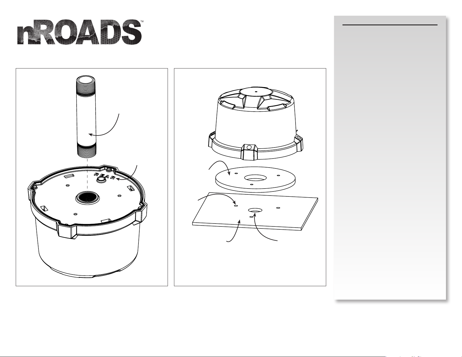
nROADS Mounting Instructions
Flat Mount:
1. Using the supplied gasket, mark the center hole
and three mounting holes on the surface the
beacon will be mounted to.
2. Drill your holes.
a. The center hole should be large enough for the
wires to pass, between 5/8" and 1".
b. The 3 mounting holes should be drilled for
clearance for #10 bolts (1/4").
3. Using #10-32 bolts of suitable length (installer
supplied) secure the beacon to the mounting
surface making sure the gasket is between
the beacon and the mounting surface. (SoundOff
Signal recommends using flat washers and lock
washers to secure the beacon to your mounting
surface).
Pipe Mount:
1. The beacon is pre-threaded to fit a 1" NPT pipe.
2. Insert wires into the pipe making connections you
wish to use.
3. Screw the beacon on the pipe until snug.
4. The aluminum base is marked "REAR". Rotate the
beacon until the "REAR" is facing the back of the
vehicle. This is important for specific light
modes.
PIPE MOUNT
2.
Mounting
Holes x3
FLAT MOUNT
Mounting
Surface
5/8"-1" Center Hole
nROADS Beacon 05.16
Page 3
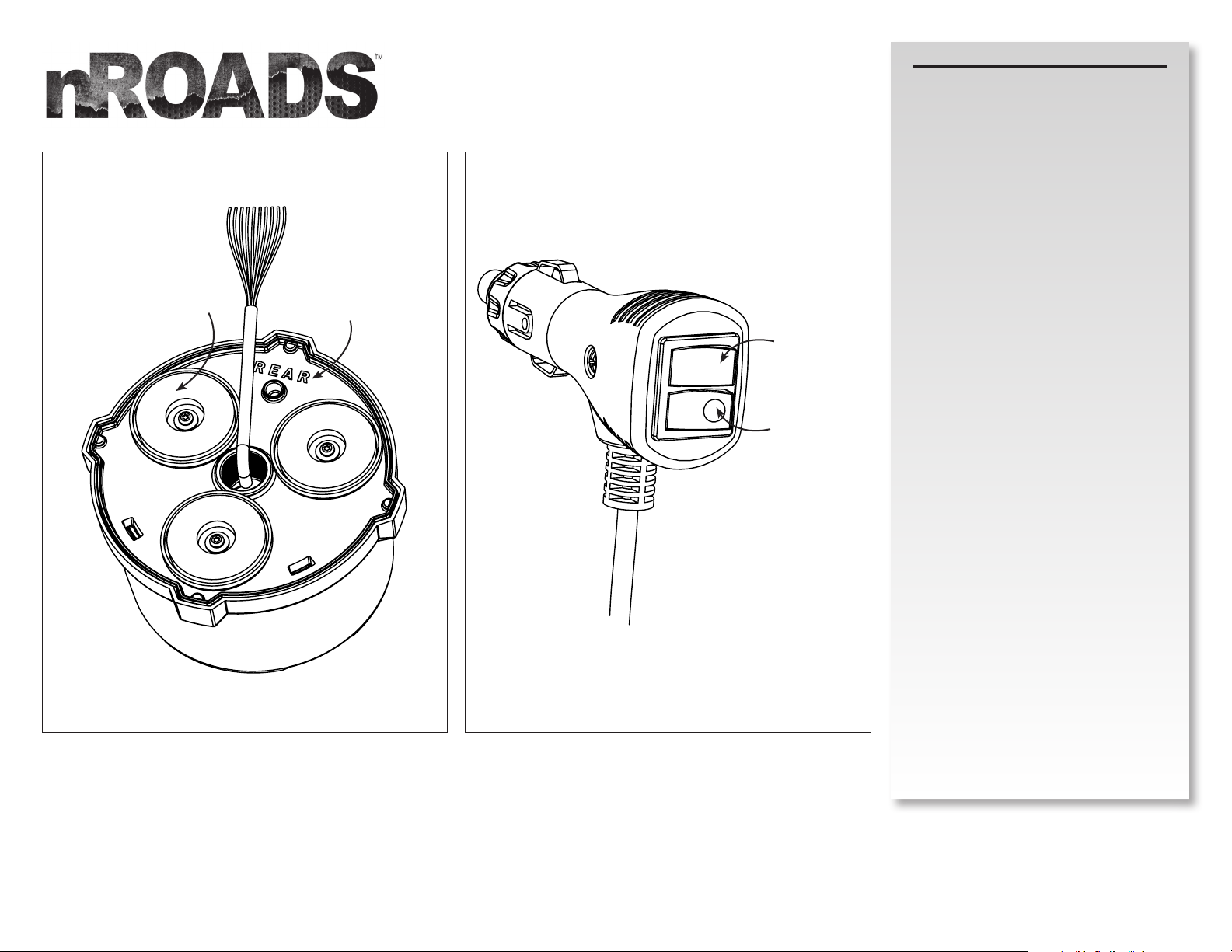
Magnets x3
"REAR" needs to face
the rear of the vehicle
nROADS Mounting Instructions
Magnet Mount:
1. Locate surface where beacon will be mounted.
2. Place beacon with the "REAR" facing the rear of
the vehicle. This is important for specific modes.
Cig Plug Operation:
1. See Cig Plug diagram at left for POWER ON/OFF
and PATTERN SELECT switch locations.
2. Turn beacon ON by pressing the POWER ON/OFF
switch to the ON position.
3. With beacon OFF, press and hold PATTERN
SELECT switch for 1 second until you see the
beacon flash the new pattern and release.
4. Holding the PATTERN SELECT switch for >5
seconds while the beacon is ON will reset the
beacon to pattern #0.
PATTERN
POWER ON/OFF
MAGNET MOUNT
3.
CIG PLUG
nROADS Beacon 05.16
Page 4
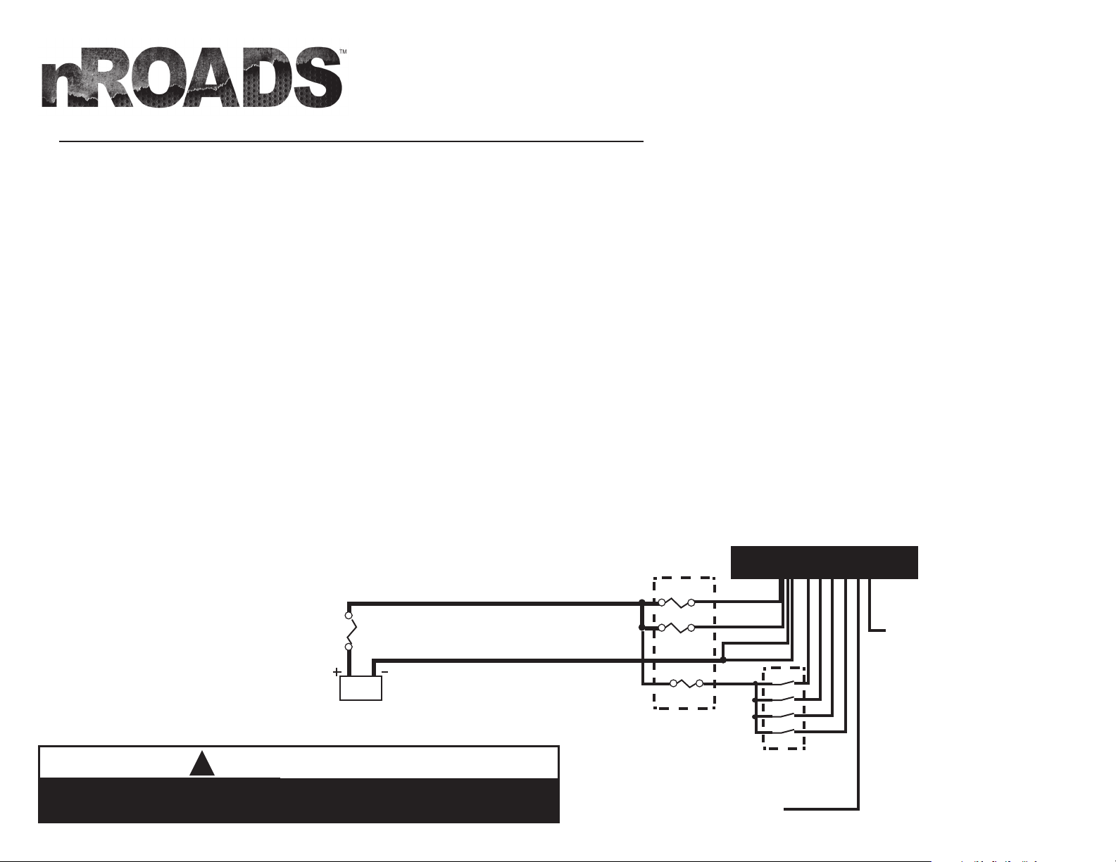
ELECTRICAL INSTALLATION (applies to permanent mounting options only)
Power Wires:
1. Route customer supplied power and ground cables which are properly sized for the current consumption of the beacon (rated for a minimum of 125% above maximum current draw) between
the power source (battery) and the beacon power and ground cables.
2. Install a maximum of 20Amp Fuse (customer supplied) to the end of the power cables as close to the power source (battery) as possible.
a. Remove the fuse before connecting any wires to the battery.
b. DO NOT USE CIRCUIT BREAKER OR FUSIBLE LINK.
3. Connect the other end of the Fuse to the POSITIVE (+) terminal of the battery.
a. Do NOT use any more than 2ft of wire between the battery terminal and the fuse and ensure the wire is protected and secured from being cut into; this is non-fused wire.
4. Connect the BLACK wire to the factory chassis ground right next to the battery and the the ground cables of the beacon.
Control Wires (Blue, Orange, Yellow & Pink):
1. Route customer supplied wires between switch panel and the Blue, Orange, Yellow, and/or Pink wires. Use 20AWG type TXL wire as required to extend the length of the wires to reach the
customer supplied switches.
2. The +12V supply to the control wires must be over-current protected to protect the wires and product against the possibility of a short circuit. A 1 amp fuse will be sufficient since the control
wire inputs require less than 10mA per input to activate.
Synch Wire (Green):
1. Connect the green wire to other Sync2 compatible products (nFORCE Secondary Light, nFORCE FIT & Dual Color Intersector Lights) which are on the vehicle and need to synchronize the flash
pattern. All product with the green wires connected must be operating
the same flash pattern otherwise incorrect flash pattern timing will occur.
2. If synchronized flash patterns to other product are not required, blunt cut and tape the end of the green wire to ensure the wire is protected from being unintentionally grounded while in service.
Pattern Select/Configuration Wire (White):
1. Applying a momentary ground on the white wire will configure the product. Refer to the production configuration section of the installation instructions for setup.
2. Once product is configured, blunt cut and tape the end of the white wire to ensure the wire is protected from being unintentionally grounded while in service and changing the configuration.
+9-17.5Vdc
Customer Supplied Wire
20AMP
Ground
Customer Supplied Wire
BATTERY
WARNING
!
ALL CUSTOMER SUPPLIED POWER WIRES CONNECTING TO THE POSITIVE (+) OR NEGATIVE (-) BATTERY
TERMINAL OR LOCAL CHASIS GROUND (-) MUST BE SIZED TO SUPPLY AT LEAST 125% OF THE MAXIMUM
CURRENT AND PROPERLY FUSED AT THE POWER SOURCE WITH APPROPIATELY RATED FUSE.
4.
10AMP
10AMP
1AMP
Customer Supplied
Fuses
Momentary Ground
to Configure Product
Red
Red
Black
Black
Customer Supplied
Blue
Switches
Pattern Select
Yellow
Orange
Pink
Green
White
Sync Wire
Connected to Other Sync 2 Products
to Synchronize Flash Pattern (nFORCE
Secondary Light, nFORCE FIT & Dual Color
Intersector Lights)
nROADS Beacon 05.16
Page 5

ELECTRICAL INSTALLATION (CONTINUED)
Product Configuration:
1. The four control wires (blue, orange, yellow and pink) can each be assigned a function from the flash pattern table, which include:
a. Output a pattern,
b. Enable a scene (where lights are steady on),
c. Enable cruise mode (lights are on dimly), or
d. Set lightbar to reduced power (night) mode.
2. Functionality is assigned to the control wires by applying +12V supply to the control wire and then grounding the white wire for a specific amount of time.
a. To advance the next function in the list, tap the white wire to ground for < 1 second.
b. To go back one function in the list, hold the white wire to ground for >1 second and < 2 seconds.
c. To set the wire functionality to the default value, hold the white wire to ground >1 second and < 3 seconds.
d. For beacons with more than one color, hold the white wire to ground for >3 seconds to set the color(s) used with the active control wire.
3. For beacons with multiple colors, the color(s) used for each control wire is set by grounding the white wire while applying +12V to the desired control wire for > 3 seconds.
a. After 3 seconds, each color will turn on for 1 second. Release the white wire during this time to set the control wire function to the displayed color.
b. Once all colors have been displayed, color combinations will light such that the 2 colors will alternate (½ second color 1 and ½ second color 2) for 3 times, followed by ½ second off. Release the white wire
during this time to set the control wire function to the 2 flashing colors.
4. The control board obtains information about the attached modules through a learning procedure that is performed in the factory. If the hardware is changed to
modules of different types (e.g. colors are changed), the learning process will need to be repeated.
a. If device is a beacon, ensure DIP Switch 2 is ON. If Light bar it should be OFF.
b. To enable sync2 ensure DIP Switch 3 is ON. To disable sync2 ensure DIP Switch 3 is OFF.
c. Move the DIP Switch 1 from OFF to ON and back to OFF to start the learning process.
d. After approximately 2 seconds (during which time the lights may flicker briefly), all lights of each color will turn on for 2 seconds each. Observe the modules
to make sure they are the proper color.
Operating Modes:
1. Flash Pattern
Light modules will flash with selected pattern. If multiple control wires are set to output a pattern are active simultaneously
the wire with the highest priority will be active (Pink > Yellow > Orange > Blue).
2. Scene
Modules for scene will stay on continuously. If only some light modules are used for the scene then a flash pattern can
be active on other light modules.
3. Cruise
Selected modules will stay on continuously at a dim value. Patterns and Scenes will take priority over a cruise function
if both are active.
4. Low Power
If a low power functionality is enabled along with a pattern or scene, the pattern or scene will be active at a lower light output level.
5. Sleep
If no input is active, the device will enter a low power sleep mode.
5.
WARNING
!
Route wires only in locations that are not subjected to
potential wear. Make sure to avoid routing wires in the
deployment area of your air bag. Refer to your vehicle’s
owner’s manual for airbag deployment zone.
IMPORTANT
WHEN PASSING CABLES THROUGH FIREWALL OR OTHER
SHEETMETAL, INSERT GROMMET TO PROTECT THE CABLE!
nROADS Beacon 05.16
Page 6

FLASH PATTERNS
*fpm=Flashes per Minute
**fps=Flashes per Second
# Name
SAE
Compliant
Sequence fpm fps
nROADS to nROADS
Compatible
Sync2 Compatible
0 RandomAction 1 Yes Variable - - Yes n/a
1 RandomAction 2 Variable - - Yes n/a
RandomAction 3 (Blue wire/Cig Plug
2
default)
Variable - -
3 RandomAction 4 (Orange wire default) Variable - -
4 Rotate 250 Yes Rotating - -
5 Rotate 125 Yes Rotating - -
6 Race 200 (Rotate w/ Chaser) Yes Rotating - -
7 Race 125 Yes Rotating - -
8 Race 100 Yes Rotating - -
9 Race 200 w/ TripplePop Variable - -
10 Cross-Fire 2X Individual Sweep - -
11 Super Scan Dual Rate Pulse/Alt - -
LED Module Count Dependent
LED Module Count Dependent
LED Module Count Dependent
LED Module Count Dependent
LED Module Count Dependent
LED Module Count Dependent
LED Module Count Dependent
LED Module Count Dependent
LED Module Count Dependent
LED Module Count Dependent
n/a
n/a
n/a
n/a
n/a
n/a
n/a
n/a
n/a
n/a
12 Power Flash Dual Rate Alt/Pulse - - Yes n/a
13 Thunder and Lightning Random - - Ye s n/a
14 8TriplePop Yes Sim - 3.7, 1.5 Yes n/a
15 Quint Yes Alt L/R 67 1.1 Yes Yes
16 Quint Yes Sim 67 1.1 Yes Yes
17 Quint Yes Alt²/Sim 67 1.1 Yes Yes
18 Quad2 Yes Alt L/R 67 1.1 Ye s Yes
19 Quad2 Yes Sim 67 1.1 Yes Yes
20 Quad2 Yes Alt²/Sim 67 1.1 Yes Yes
21 Q-Switch™ Variable - Yes Ye s
22 Double Yes Alt L/R 115 1.9 Yes n/a
6.
nROADS Beacon 05.16
Page 7

*fpm=Flashes per Minute
FLASH PATTERNS CONTINUED
# Name
SAE
Compliant
Sequence fpm fps nROADS to nROADS Compatible Sync2 Compatible
**fps=Flashes per Second
22 Double Ye s Alt L/R 115 1.9 Yes n/a
23 Double Ye s Sim 115 1.9 Yes n/a
24 Double Ye s Alt²/Sim 115 1.9 Yes n/a
25 Power Pulse Yes Alt L/R 188 3.1 Yes Yes
26 Power Pulse Yes Sim 188 3.1 Yes Yes
27 Power Pulse Yes Alt²/Sim 188 3.1 Yes Yes
28 Road Runner Yes Alt L/R 115 1.9 Yes Ye s
29 Road Runner Yes Sim 115 1.9 Yes Yes
30 Road Runner Yes Alt²/Sim 115 1.9 Yes Yes
31 Slow Runner Yes Alt L/R 70 1.2 Yes n/a
32 Slow Runner Yes Sim 70 1.2 Yes n/a
33 Slow Runner Yes Alt/Sim 70 1.2 Yes n/a
34 Warp Alt L/R 333 5.6 Yes Yes
35 Warp Sim 333 5.6 Yes Ye s
36 Warp Alt²/Sim 333 5.6 Yes Yes
37 Intercycle Alt L/R 67 & 333 1.1 & 5.6 Yes Yes
38 Intercycle Sim 67 & 333 1.1 & 5.6 Yes Yes
39 Intercycle Alt²/Sim 67 & 333 1.1 & 5.6 Yes Ye s
40 Warp 1, 2, 3 Alt L/R 115-333 1.9 - 5.6 Ye s n/a
41 Warp 1, 2, 3 Sim 115-333 1.9 - 5.6 Yes n/a
42 Warp 1, 2, 3 Alt²/Sim 115-333 1.9 - 5.6 Yes n/a
43 All Cruise 3%
44 All Cruise 7% (Yellow wire default)
Cruise Mode Control (pattern overlay capable)
Cruise Mode Control (pattern overlay capable)
n/a n/a
n/a n/a
45 Left Scene Scene Control n/a n/a
7.
nROADS Beacon 05.16
Page 8

FLASH PATTERNS CONTINUED
# Name
46 Right Scene Scene Control n/a n/a
47 Front Scene Scene Control n/a n/a
48 Rear Scene Scene Control n/a n/a
49 All Scene Scene Control n/a n/a
50 Low Power 30% Low Power Mode Control (1 Wink) n/a n/a
51 Low Power 50% (Pink wire default) Low Power Mode Control (2 Winks) n/a n/a
Sync2 Compatibility Chart
(nFORCE Secondary, nFORCE FIT, Dual Color Intersector)
PATTERN #
1 QUINT Yes
2 WARP Yes
3 INTER-CYCLE Yes
4 DOUBLE -
5 QUAD -
6 POWER PULSE Yes
7 ROAD RUNNER Yes
8 Q-SWITCH Yes
9
10
11 QUAD 2 -
12 DOUBLE 2 -
13 RANDOM 1 -
14 RANDOM 2 -
SINGLE
COLOR
(SEQUENCE TYPE 1: STEADY BURN, SEQUENCE
STEADY-BURN DRIVER TITLE 13 QUAD
(SEQUENCE TYPE 1: STEADY BURN, SEQUENCE
DUAL COLOR TRI-COLOR nROADS Compatible
STEADY-BURN / ROADRUNNER
TYPE 2: ROADRUNNER)
TYPE 2: TITLE 13 QUAD)
SAE
Compliant
Sequence fpm fps nROADS to nROADS Compatible Sync2 Compatible
NOTE:
For Simultaneous or Alternating flash pattern, set the
sequence type on the secondary product.
-
Yes
-
-
nROADS Beacon 05.16
8.
Page 9

REPLACEMENT PARTS & ACCESSORIES
ITEM
#
1 PNRBCDRV2 DRIVER W/ CONNECTOR
2 PNRBCDRV1 DRIVER W/O CONNECTOR
3 PNRBCLUP6A UPWARD LIGHT ENGINE
3 PNRBCLUP6B UPWARD LIGHT ENGINE
3 PNRBCLUP6G UPWARD LIGHT ENGINE
3 PNRBCLUP6R UPWARD LIGHT ENGINE
3 PNRBCLUP6W UPWARD LIGHT ENGINE
4 PNRBCDMHA AMBER HIGH DOME
5 PNRBCDMHC CLEAR HIGH DOME
6 PNRBCDRNGB BLACK DRESS RING
PART# DESCRIPTION
PNRBCHNJP1 UPWARD LED JUMPER HARNESS
4 5
21
3
6
nROADS Beacon 05.16
9.
Page 10

nROADS TROUBLESHOOTING
Normal Operation
Under normal operation the Beacon will Flash when a combination of the four control inputs are connected to +Vdc. The Beacon is OFF and in a low power Standby Mode after 10 seconds of no active control inputs.
No Operation
No Power; Check Red main Power feeds have a solid connection with +Vdc present on the wire post fuse. A minimum of +9Vdc is required. Replace fuse if necessary.
Verify Red main Power feeds have not exceeded voltage cutoff threshold of +17.5Vdc. Lower voltage to regain operation.
Check Black main Ground feeds have a solid and low resistance connection to ground.
No Lights; Verify at least one of the four control inputs is present with +Vdc.
Verify pattern is able to advance and control wire is not set to a Low power mode, pattern 50-51. (Blue wire default)
Perform product configuration (pg. 5).
No or Incorrect Warning Light Flash
No operation; Verify correct Control Input wire is present with +Vdc.
Verify pattern is able to advance and control wire is not set to a Low power mode, pattern 50-51. (Blue wire default)
Perform product configuration (pg. 5).
Incorrect/Undesired operation; Check that another control input is not active which has Flash priority over current control input. (pg. 4).
Low Power and Scene Light override flashing mode regardless of wire priority. Remove Low Power or Scene light control input.
No or Incorrect Scene Lights
No Lights; Verify correct Control Input wire is present with +Vdc.
Verify pattern is able to advance and control wire is set to pattern 45-49.
Perform product configuration (pg. 5).
Incorrect/Undesired operation; Check that another control input does not have an active Scene with priority over current control input. (pg. 4). Low Power overrides Scene Light wire priority. Remove Low
Power control input.
No or Incorrect Synchronization
No or Incorrect syncing; Verify green wires are connected between all required Sync 2 products.
Verify Flash patterns are set to the same one. Patterns 12-42 are sync capable with all Sync2 product.
Depending on led module count, Random and rotating patterns (0-11) may not sync correctly between products (ex. Mini-Lightbar & Dual Stack Beacon). Scene, Cruise or Low
Power are not sync capable.
Erratic Flash Verify Flash patterns are set to the same one.
Check that the green and/or white wire is not being intermittently shorted to ground. Securely seal all connections.
nROADS Beacon 05.16
10.
Page 11

WARRANTY RETURN PROCESS:
Please contact your SoundOff Signal Sales Representative, Customer Services
staff or our Technical Department (800.338.7337 option #4) for a RMA #,
Return Merchandise Authorization Number.
The following information is required for issuance of the RMA #:
• Reason for returning the product*
• Address where replacement product is to be shipped*
• Telephone number where you may be reached*
• SoundOff Signal invoice number on which product was purchased**
• SoundOff Signal part number and serial number**
• E-mail address where RMA # should be e-mailed**
• Fax number where RMA # should be faxed**
* RMA # will not be given without this information.
** If available, please provide this information.
SoundOff Signal will NOT accept returns without an RMA #. Each RMA #
is good for only one (1) return and will expire (30) days after the date it was
issued. Products must be shipped back to SoundOff Signal and the RMA #
clearly marked on the outside of the package near the shipping label. Please
use the following address on your shipping label:
SoundOff Signal
ATTN: RMA # / Technical Services
3900 Central Parkway
Hudsonville, MI 49426
WARRANTY EXCLUSIONS:
Shipping & Handling, labor and service fees are non-refundable. SoundOff
Signal is not liable for any damage due to installation or personal injury as a
result of using SoundOff Signal product.
WARRANTY FORFEITURE:
Warranty will not be granted if the Warranty Return Policy & Procedure rules
are not strictly followed. Physical damage resulting from customer abuse
will void warranty. Warranty will also be voided if any SoundOff Signal and/
or manufacturer serial tags, product stickers, seals, or the like, are removed,
altered or tampered with. Returned product that is damaged by shipping via
the RMA # procedure is not the responsibility of SoundOff Signal.
Document effective date on cover and below supersedes previously dated
policies and statements.
There are no other warranties, expressed or implied, including, but not limited
to, any implied merchantability or fitness for a particular use. SoundOff
Signal reserves the right to modify this warranty statement at any time; or to
discontinue, modify, or upgrade any products of its manufacture with design
improvements without prior notice.
11.
nROADS Beacon 05.16
 Loading...