

Page 1
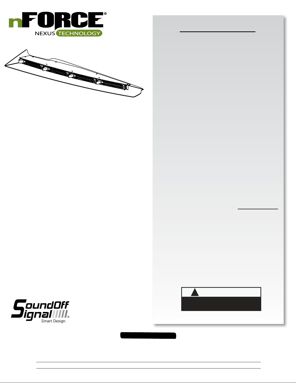
nFORCE LED Interior Lightbar
TABLE OF CONTENTS
PAGE CONTENT
1 COMPONENTS/ CONTENTS
2 TECHNICAL/ POWER SPECIFICATIONS
3-7 ELECTRICAL INSTALLATION
8 CONTROL HARNESS
9 LIGHT MODULE WIRE HARNESS LOCATIONS &
DRIVER MODULE REPLACEMENT
IMPORTANT NOTICE TO INSTALLER: Make sure to read and understand
all instructions and warnings before proceeding with the installation of this
product. Ensure that the manual and any warning cards are delivered to the
end user of this equipment. Proper installation of the lightbar requires the
installer to have a thorough knowledge of automotive electronics, systems,
and procedures. Lightbars provide an essential function of an effective visual
warning system. The use of the lightbar does not insure that all drivers can
or will abide by or react to an emergency warning signal, especially at high
rates of speeds or long distances. The operator of the vehicle must never take
the right of way for granted and it is the operator’s responsibility to proceed
safely. The effectiveness of the lightbar is highly dependant on the correct
mounting and wiring. The installer must read and follow the manufacturer’s
installation instructions and warnings in the manual. The vehicle operator
should verify daily that the lightbar is securely fastened to the vehicle and
properly functioning before operating vehicle. The lightbar is intended for use
by authorized personnel only. It is the user’s responsibility to ensure they
understand and operate the emergency warning devices in compliance with
the applicable city, state and federal laws and regulations. SoundOff Signal
assumes no liability for any loss resulting from the use of this warning device.
Components/Contents
Standard Equipment:
1 - nForce™ LED Interior Lightbar built to your specifications
1 - Breakout Box
1 - 24 Pin Harness
1 - Mounting Hardware
Unpack Lightbar
1. Remove the lightbar from box and packaging.
2. Save packaging for later shipping.
3. Check components/contents.
4. Please reference these instructions for proper wiring and installation.
10 NFORCE TROUBLESHOOTING
11 CONNECTION OF BREAKOUT BOX TO SOUNDOFF
SIGNAL SIRENS
12 REPLACEMENT PARTS
13 WARRANTY AND RETURN GOODS PROCEDURE
Important Information:
• Warning devices are strictly regulated and governed by Federal, State
and Municipal ordinances. These devices shall be used ONLY on approved
vehicles. It is the sole responsibility of the user of these devices to ensure
compliance.
• DO NOT install this product or route any wires in the Air Bag Deployment
Zone. Refer to your vehicle Owner’s Manual for the location of any air
bag deployment zones.
• DO NOT connect this device to a strobe power supply. This product is
self-contained and does not require an external power supply.
WARNING
!
This product contains high intensity LED devices. To
prevent eye damage, DO NOT stare into the light
1.800.338.7337 / www.soundoffsignal.com
IMPORTANT INFORMATION:
Warning devices are strictly regulated and governed by Federal, State and Municipal ordinances. These devices shall be used ONLY on approved vehicles. It is the sole responsibility of the user of these devices to ensure compliance.
To review our Limited Warranty Statement & Return Policy for this or any SoundOff Signal product, visit our website at www.soundoffsignal.com/sales-support.
If you have questions regarding this product, contact Technical Services, Monday - Friday, 8 a.m. to 5 p.m. at 1.800338.7337 (press #4 to skip the automated message).
Questions or comments that do not require immediate attention may be emailed to techservices@soundoffsigal.com.
SUPERIOR CUSTOMER RELATIONSHIPS. SMARTLY DESIGNED LIGHTING & ELECTRONIC SOLUTIONS.
1.
beam at close range.
ENFWBF(xx)0(x) 5.14
Page 2
nFORCE LED Interior Lightbar
Ignition ON
Ignition OFF
Ignition ON
Ignition OFF
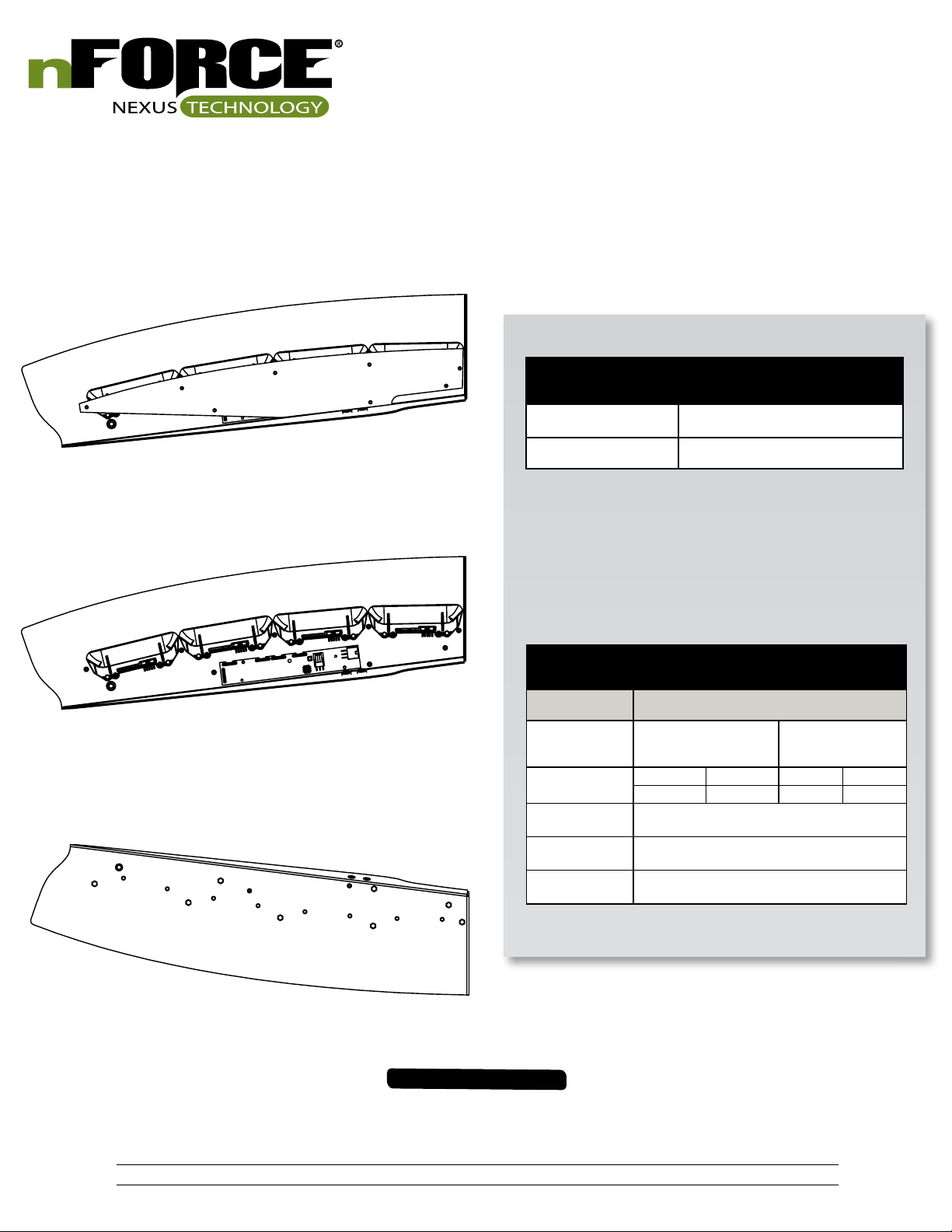
TOP VIEW WITH COVER ON
FRONT
TECHNICAL SPECIFICATIONS
Material: Powder Coated Sheet Steel
REAR
TOP VIEW WITH COVER OFF
FRONT
REAR
BOTTOM VIEW
REAR
Operating Temperature: -40º to +85º C
POWER SPECIFICATIONS
Input Voltage Range:
Light Bar
Component
Standby Current
Reverse Polarity
Load Dump
Wiring
Current Draw
(Average = Flashing)
0.010 Amps 0.002 Amps 0.13 Watts 0.03 Watts
Power Cable 25ft 18 AWG Wires, (+) Red, (-) Black,
10 -16 Vdc
Power Consumption
Protected
Protected
(Data) White
(Watts)
FRONT
IMPORTANT INFORMATION:
Warning devices are strictly regulated and governed by Federal, State and Municipal ordinances. These devices shall be used ONLY on approved vehicles. It is the sole responsibility of the user of these devices to ensure compliance.
To review our Limited Warranty Statement & Return Policy for this or any SoundOff Signal product, visit our website at www.soundoffsignal.com/sales-support.
2.
If you have questions regarding this product, contact Technical Services, Monday - Friday, 8 a.m. to 5 p.m. at 1.800338.7337 (press #4 to skip the automated message).
SUPERIOR CUSTOMER RELATIONSHIPS. SMARTLY DESIGNED LIGHTING & ELECTRONIC SOLUTIONS.
Questions or comments that do not require immediate attention may be emailed to techservices@soundoffsigal.com.
ENFWBF(xx)0(x) 5.14
Page 3
nFORCE LED Interior Lightbar
ELECTRICAL INSTALLATION
Featured Highlights & Terminology:
Mode Select: The nForce Interior Lightbar is equipped with 4 selectable pattern configuration modes. The default input wire configuration allows
for 2 modes, and an additional 2 modes may be configured with the PC Application using any available input wires. Default is Mode 1 where the
Mode select input is floating, Mode 2 is in use when the input activated. This feature allows up to 4 completely different sets of patterns to be
programmed into the Light-bar's non-volatile memory. Once programming configuration is complete, the Mode can be changed “on-the-fly” by an
activation switch which applies voltage to the Mode input wire(s).
Front & Rear Installations:
Cruise Mode: Allows the user to program any light group(s) to “Glow” when this feature is activated. For dual / tri color bars, the color for each
light group is selectable.
Takedown Mode: Allows the user to program any Light Head Group(s) to turn on steady when this feature is activated to provide steady ON
takedown lighting.
Steady ON Mode: Accessable with PC App only and allows the user to program any light module to turn on steady at 50% duty cycle.
Scene Light Mode: Allows the user to program any Light Head Group(s) to turn on steady when this feature is activated to provide additional
scene lighting. The activation of this input also activates the Takedown function
Low Power Mode: Operates lighting at reduced intensity.
Rear Installations:
Stop / Tail / Turn Mode: Allows the user to program any Light Head Group(s) to turn operate in 2 levels of intensity for tail and stop/turn func-
tions.
Directional Arrow Built-in: The directional controller is built-in w/ 9 arrow patterns for each of the 3 modes (left arrow, right arrow, and center
out arrow) and the color is selectable for dual / tri color bars
WARNING
!
ALL CUSTOMER SUPPLIED POWER WIRES CONNECTING TO THE POSITIVE (+) OR NEGATIVE (-) BATTERY
TERMINAL OR LOCAL CHASIS GROUND (-) MUST BE SIZED TO SUPPLY AT LEAST 125% OF THE MAXIMUM
CURRENT AND PROPERLY FUSED AT THE POWER SOURCE WITH APPROPIATELY RATED FUSE.
Power Cable:
1. Route lightbar power cables as close to vehicles power source (battery) as possible.
2. Install a maximum of 15 Amp Fuse (customer supplied) to the end of the RED wire of the Lightbar Power Cable.
a. Remove the fuse before connecting any wires to the battery.
b. DO NOT USE CIRCUIT BREAKER OR FUSIBLE LINK.
3. Connect the other end of the Fuse to the POSITIVE (+) terminal of the battery or other high current source.
a. Do NOT use any more than 2ft of wire between the power source and the fuse and ensure the wire is
protected and secured from being cut into; this is non-fused wire.
4. Connect the BLACK wire to the factory chassis ground right next to the battery or other ground location capable of handling
high current.
5. Connect the White wire to the Light Green wire on the breakout box. Make sure connection is insulated from other wire
connections and vehicle ground
Ignition Wire:
1. Connect the Pink/White wire to a switched power source.
IMPORTANT INFORMATION:
Warning devices are strictly regulated and governed by Federal, State and Municipal ordinances. These devices shall be used ONLY on approved vehicles. It is the sole responsibility of the user of these devices to ensure compliance.
To review our Limited Warranty Statement & Return Policy for this or any SoundOff Signal product, visit our website at www.soundoffsignal.com/sales-support.
If you have questions regarding this product, contact Technical Services, Monday - Friday, 8 a.m. to 5 p.m. at 1.800338.7337 (press #4 to skip the automated message).
Questions or comments that do not require immediate attention may be emailed to techservices@soundoffsigal.com.
SUPERIOR CUSTOMER RELATIONSHIPS. SMARTLY DESIGNED LIGHTING & ELECTRONIC SOLUTIONS.
3.
ENFWBF(xx)0(x) 5.14
Page 4

nFORCE LED Interior Lightbar
ELECTRICAL INSTALLATION (CONTINUED)
Initial Power up Test: Breakout Box needs Power (+12V to PIN 17) & Ground (PIN 4) in order to operate.
1. Insert Fuse(s) into Fuse Holder(s).
2. Observe the GREEN Data Link indicator LED on the Breakout Box; the LED will turn ON.
3. The Red indicator LED on the breakout box will be steady ON whenever any of the input wires are active
Low Power (Standby) Mode (reduced standby current)
If there is no input to the breakout box the lightbar will go into a “standby” mode. The standby mode is a low power mode that is used to extend
the life of your battery. The lightbar will awaken from the standby mode if any input is activated on the breakout box.
IMPORTANT INFORMATION:
Warning devices are strictly regulated and governed by Federal, State and Municipal ordinances. These devices shall be used ONLY on approved vehicles. It is the sole responsibility of the user of these devices to ensure compliance.
To review our Limited Warranty Statement & Return Policy for this or any SoundOff Signal product, visit our website at www.soundoffsignal.com/sales-support.
If you have questions regarding this product, contact Technical Services, Monday - Friday, 8 a.m. to 5 p.m. at 1.800338.7337 (press #4 to skip the automated message).
Questions or comments that do not require immediate attention may be emailed to techservices@soundoffsigal.com.
SUPERIOR CUSTOMER RELATIONSHIPS. SMARTLY DESIGNED LIGHTING & ELECTRONIC SOLUTIONS.
4.
ENFWBF(xx)0(x) 5.14
Page 5

nFORCE LED Interior Lightbar
ELECTRICAL INSTALLATION (CONTINUED)
Warning Flash Pattern Configuration:
a. Set Switch #2 on Breakout box to down position (Switch #1 must be in Up position)
b. Apply voltage to the activation wire of the function which requires pattern to be changed (i.e. Front Corner, Takedown, Left Alley, etc.)
c. Apply voltage to the Mode activation wire to configure mode 2 flash patterns, leave Mode activation wire floating to configure mode 1
flash patterns
d. Momentarily apply voltage to the pattern select wire to change the warning flash pattern
e. Set Switch #2 on Breakout box to up position to save settings and return light-bar to normal operating mode
FLASH PATTERNS
SAE
# Name
1 Random Single #1
2 Random Single #2
3 Quint
4 Quad 2
5 Q-Switch
6 Double
7 Power Pulse
8 RoadRunner
9 SlowRunner
10 Warp
11 Inter-cycle
12 Warp 1, 2, 3
13 E-Single
14 E-Double
15 E-Triple
16 Random Duo #1
17 Random Duo #2
18 Quint Duo
19 Quad 2 Duo
20 Q-Switch Duo
21 Double Duo
22 Power Pulse
23 RoadRunner Duo
24 SlowRunner Duo
25 Warp Duo
26 Inter-cycle Duo
27 Warp 1, 2, 3, Duo
28 Dual Color Flash 1
29 Dual Color Flash 2
30 Impact
31 Explosion
32 Tri Color Flash 1
Compliant
Timing
Yes
No
Yes
Yes
Yes
Yes
Yes
Yes
Yes
No
No
No
Yes
Yes
Yes
Yes
No
Yes
Yes
No
Yes
Yes
Yes
Yes
Color Sequence fpm fps
#1
#1
#1
#1
#1
#1
#1
#1
#1
#1
#1
#1
#1
#1
#1
#1/2
#1/2
#1/2
#1/2
#1/2
#1/2
#1/2
#1/2
#1/2
Variable - Variable - -
Alternating 70 1.2
Variable - -
Variable - Alternating 115 1.9
Alternating 180 3.0
Alternating 115 1.9
Alternating 70 1.2
Alternating 350 5.8
Alternating - -
Variable - Alternating 125 2.1
Alternating 125 2.1
Alternating 125 2.1
Variable - -
Variable - Alternating 70 1.2
Variable - -
Variable - Alternating 115 1.9
Alternating 180 3.0
Alternating 115 1.9
Alternating 70 1.2
No #1/2 Alternating 350 5.8
No #1/2 Alternating - No #1/2 Variable - No #1/2 Variable - No #1/2 Variable - No #1/2 Variable - No #1/2 Variable - No #1/2/3 Alternating - -
NOTE: Takedown and Alley light patterns
are limited to pattern #1 – 15
*fpm=Flashes per Minute
**fps=Flashes per Second
IMPORTANT INFORMATION:
Warning devices are strictly regulated and governed by Federal, State and Municipal ordinances. These devices shall be used ONLY on approved vehicles. It is the sole responsibility of the user of these devices to ensure compliance.
To review our Limited Warranty Statement & Return Policy for this or any SoundOff Signal product, visit our website at www.soundoffsignal.com/sales-support.
If you have questions regarding this product, contact Technical Services, Monday - Friday, 8 a.m. to 5 p.m. at 1.800338.7337 (press #4 to skip the automated message).
Questions or comments that do not require immediate attention may be emailed to techservices@soundoffsigal.com.
SUPERIOR CUSTOMER RELATIONSHIPS. SMARTLY DESIGNED LIGHTING & ELECTRONIC SOLUTIONS.
5.
ENFWBF(xx)0(x) 5.14
Page 6

nFORCE LED Interior Lightbar
ELECTRICAL INSTALLATION (CONTINUED)
NOTE: For settings below, Switch #2 does not need to be moved to the up position after each configuration. The switch can
remain in the down position until the lightbar is completely configured and then moved to the Up position to store all the settings.
Cruise Mode Configuration:
a. Set Switch #2 on Breakout box to down position (Switch #1 must be in Up position)
b. Determine which module inputs are needed for cruise mode
c. Apply voltage to the Cruise Mode activation wire
d. Apply voltage to the light group wire(s) required (i.e. Front Corner, Front Inboard 1, etc.)
e. Momentarily apply voltage to the pattern select wire to change the color between Off, Color 1, Color 2, and Color 3.
NOTE: If configuring a single color or dual color module, make sure the chosen color is configured for Off and not a color which does not
exist on the module. The lightbar will flash color #1 of all modules configured for cruise mode. If a module flashes every 2 seconds and is
not intended to be on when Cruise mode is activated, repeat steps ‘d’ and ‘e’ until module no longer flashes.
f. Set Switch #2 on Breakout box to up position to save settings and return light-bar to normal operating mode
Takedown and Work-light Configuration:
a. Set Switch #2 on Breakout box to down (Switch #1 must be in Up position)
b. Determine which module inputs are needed for Takedowns or Work-lights
c. Apply voltage to the Takedown activation wire
d. Apply voltage to the light group wire(s) required (i.e. Front Inboard 1, Rear Inboard 2, etc.)
e. Momentarily apply voltage to the pattern select wire to change the color between Off, Color 1, Color 2, and Color 3.
NOTE: If configuring a single color or dual color module, make sure the chosen color is configured for Off and not a color which does not exist on the module. The light-bar will flash color #1 of all modules configured for takedown. If a module flashes every 2 seconds and is not
intended to be on when takedown is activated, repeat steps ‘d’ and ‘e’ until module no longer flashes.
f. Set Switch #2 on Breakout box to up position to save settings and return light-bar to normal operating mode
Scene light Configuration:
a. Set Switch #2 on Breakout box to down (Switch #1 must be in Up position)
b. Determine which module inputs are needed for Scene Lighting
c. Apply voltage to the Scene light activation wire
d. Apply voltage to the light group wire(s) required (i.e. Front Inboard 1, Rear Inboard 2, etc.)
e. Momentarily apply voltage to the pattern select wire to change the color between Off, Color 1, Color 2, and Color 3.
NOTE: If configuring a single color or dual color module, make sure the chosen color is configured for Off and not a color which does not
exist on the module. The light-bar will flash color #1 of all modules configured for scene light. If a module flashes every 2 seconds and is
not intended to be on when scene light function is activated, repeat steps ‘d’ and ‘e’ until module no longer flashes.
f. Set Switch #2 on Breakout box to up position to save settings and return light-bar to normal operating mode
IMPORTANT INFORMATION:
Warning devices are strictly regulated and governed by Federal, State and Municipal ordinances. These devices shall be used ONLY on approved vehicles. It is the sole responsibility of the user of these devices to ensure compliance.
To review our Limited Warranty Statement & Return Policy for this or any SoundOff Signal product, visit our website at www.soundoffsignal.com/sales-support.
If you have questions regarding this product, contact Technical Services, Monday - Friday, 8 a.m. to 5 p.m. at 1.800338.7337 (press #4 to skip the automated message).
Questions or comments that do not require immediate attention may be emailed to techservices@soundoffsigal.com.
SUPERIOR CUSTOMER RELATIONSHIPS. SMARTLY DESIGNED LIGHTING & ELECTRONIC SOLUTIONS.
6.
ENFWBF(xx)0(x) 5.14
Page 7

nFORCE LED Interior Lightbar
Stop / Turn / Tail (STT) Light Configuration:
a. Set Switch #2 on Breakout box to down position (Switch #1 must be in Up position)
b. Determine which module inputs are needed for Stop / Turn / Tail Lights
c. Apply voltage to the Left Turn or Right Turn activation wires
d. Apply voltage to the light group wire(s) required (i.e. Rear Inboard 1, Rear Inboard 2, etc.)
e. Momentarily apply voltage to the pattern select wire to change the color between Off, Color 1, Color 2, and Color 3.
NOTE: If configuring a single color or dual color module, make sure the chosen color is configured for Off and not a color which does
not exist on the module. The light-bar will flash color #1 of all modules configured for STT function. If a module flashes every 2
seconds and is not intended to be on when an STT function is activated, repeat steps ‘d’ and ‘e’ until module no longer flashes.
f. Set Switch #2 on Breakout box to up position to save settings and return light-bar to normal operating mode
Arrow Color Configuration:
a. Set Switch #2 on Breakout box to down position (Switch #1 must be in Up position)
b. Determine which module inputs are needed for Arrow function
c. Apply voltage to the Left Arrow or Right Arrow activation wires
d. Apply voltage to the light group wire(s) required (i.e. Rear Inboard 1, Rear Inboard 2, etc.)
e. Momentarily apply voltage to the pattern select wire to change the color between Off, Color 1, Color 2, and Color 3.
NOTE: If configuring a single color or dual color module, make sure the chosen color is configured for Off and not a color which does
not exist on the module. The light-bar will flash color #1 of all modules configured for Arrow function. If a module flashes every 2
seconds and is not intended to be on when an Arrow function is activated, repeat steps ‘d’ and ‘e’ until module no longer flashes.
ELECTRICAL INSTALLATION (CONTINUED)
f. Set Switch #2 on Breakout box to up position to save settings and return light-bar to normal operating mode.
Arrow Flash Pattern Configuration:
a. Set Switch #2 on Breakout box to down position (Switch #1 must be in Up position)
b. Apply voltage to the Left Arrow activation wire to set Left Arrow pattern, apply voltage to Right Arrow activation wire to set Right
Arrow pattern, apply voltage to Left Arrow and Right Arrow activation wires to set Center out Arrow pattern
c. Momentarily apply voltage to the pattern select wire to change the arrow flash pattern
d. Set Switch #2 on Breakout box to up position to save settings and return light-bar to normal operating mode
WARNING
IMPORTANT
WHEN PASSING CABLES THROUGH FIREWALL OR OTHER
SHEETMETAL, INSERT GROMMET TO PROTECT THE CABLE!
IMPORTANT INFORMATION:
Warning devices are strictly regulated and governed by Federal, State and Municipal ordinances. These devices shall be used ONLY on approved vehicles. It is the sole responsibility of the user of these devices to ensure compliance.
To review our Limited Warranty Statement & Return Policy for this or any SoundOff Signal product, visit our website at www.soundoffsignal.com/sales-support.
If you have questions regarding this product, contact Technical Services, Monday - Friday, 8 a.m. to 5 p.m. at 1.800338.7337 (press #4 to skip the automated message).
Questions or comments that do not require immediate attention may be emailed to techservices@soundoffsigal.com.
SUPERIOR CUSTOMER RELATIONSHIPS. SMARTLY DESIGNED LIGHTING & ELECTRONIC SOLUTIONS.
!
Route wires only in locations that are not subjected to
potential wear. Make sure to avoid routing wires in the
deployment area of your air bag. Refer to your vehicle’s
owner’s manual for airbag deployment zone.
7.
ENFWBF(xx)0(x) 5.14
Page 8

nFORCE LED Interior Lightbar
15 Amp FUSE
(Customer Supplied)
BLACK 18 GA.
GROUND
Connector Pinning Chart
24 23 22 21 20 19 18 17 16 15 14 13
12 11 10 9 8 7 6 5 4 3 2 1
TO WHITE WIRE ON LIGHTBAR
PIN#21 - Yellow/ White
PIN#20 - Brown
PIN#19 - Red/ White
PIN#18 - Pink
PIN#17 - Red
+12v
GROUND
Ignition
Switch
PIN#24 - Light Green/ White
PIN#23 - Red Black
PIN#22 - Orange/ White
RED 18 GA.
-BLUE WIRE NOT USED
-GREEN WIRE NOT USED
-BROWN WIRE NOT USED
LIGHT GRN
18 GA.
BLACK 18 GA.
RED 18 GA.
POWER
WHITE 18 GA.
CABLE
+12V
Functional Inputs
Functional Inputs connect to your control
head or switching unit. Applying +12Vdc
to any functional Input will activate it's
function (default-active high).
PIN#16 - Orange
PIN#15 - Yellow
PIN#14 - Green
PIN#13 - Blue
BREAKOUT BOX HOOKUP:
a. Refer to Table 1 for Breakout Box input wire default
functions
b. Make sure the 24-pin connector is snapped in securely.
c. Follow the label for the wire color to connect to a 12Vdc
source, which turns on that given light or lights.
d. Make sure your wire connections are secured and
isolated from any other wire.
*Works with front and/or rear Interior Lightbars
Switch #1
Switch #2
Green LED
Red LED
Wire Pin # Wire Color Wire Function
1 Blue/White Rear Inboard 4
2 Green/White Rear Inboard 1
3 Gray Mode Select
4 Black Ground
5 Light Green Data
6 Brown/White Takedown Flash
7 Purple Low Power
8 White Pattern Select / Tail
9 Black/White Left STT
10 Gray/White Arrow - Right
11 Purple/White Arrow – Left
12 Pink/White Ignition Input
13 Blue Front Inboard 4
14 Green Front Inboard 1
15 Yellow Front Inboard 2
16 Orange Front Inboard 3
17 Red V+ Input
18 Pink Scene
19 Red/White Cruise
20 Brown Takedown 1
21 Yellow/White Rear Inboard 2
22 Orange/White Rear Inboard 3
23 Red/Black Right Turn
24 Light Green/White Future use - Sync 2
Table 1.
Gray - PIN#3
Black - PIN#4
Purple - PIN#7
White - PIN#8
Pink/ White - PIN#12
Black/ White - PIN#9
Gray/ White - PIN#10
Warning devices are strictly regulated and governed by Federal, State and Municipal ordinances. These devices shall be used ONLY on approved vehicles. It is the sole responsibility of the user of these devices to ensure compliance.
To review our Limited Warranty Statement & Return Policy for this or any SoundOff Signal product, visit our website at www.soundoffsignal.com/sales-support.
If you have questions regarding this product, contact Technical Services, Monday - Friday, 8 a.m. to 5 p.m. at 1.800338.7337 (press #4 to skip the automated message).
8.
Purple/ White - PIN#11
SUPERIOR CUSTOMER RELATIONSHIPS. SMARTLY DESIGNED LIGHTING & ELECTRONIC SOLUTIONS.
Light Green - PIN#5
Brown/ White - PIN#6
Questions or comments that do not require immediate attention may be emailed to techservices@soundoffsigal.com.
Blue/ White - PIN#1
Green White - PIN#2
IMPORTANT INFORMATION:
ENFWBF(xx)0(x) 5.14
Page 9

nFORCE LED Interior Lightbar
LIGHT MODULE WIRE HARNESS LOCATIONS
#1
#2
#3
#4 #4
POWER DISTRIBUTION WIRE
#3
DRIVER BOARD
#2
REPLACEMENT OF INBOARD MODULES:
1. Disconnect main power.
2. Remove top cover by removing screws.
3. Locate module and remove mounting nuts. Remove module from lightbar.
4. Remove connector from rear of module by carefully pulling connector body from back of module.
5. Push module connector into replacement module ensuring locking latch is seated properly or connector is fully seated.
6. Replace module and hardware that fasten module to shroud.
7. Restore power to bar and test new module to ensure functionality.
8. Replace top cover of bar with screws removed in step 2.
Driver Module Replacement:
a. Verify power has been removed from lightbar before attempting service
b. Remove cover
c. Unplug 3 and / or 6 pin power/data connector(s) and LED module connectors from driver module assembly, noting location.
d. Remove driver module
e. Attach new driver module assembly into housing
f. Plug 3 and/or 6 pin power/data connector(s) and LED module connectors into driver module assembly
g. Set DIP switch according to lightbar location and driver module location as shown below:
h. Apply power to lightbar and verify proper operation.
i. Set Switch #2 on Breakout Box to Down position then to Up position to store configuration into new driver module
j. If lightbar does not function properly, verify DIP switch settings and change if not correct, then repeat step ‘i’
#1
DRIVER SIDE
FORWARD FACING
REARWARD FACING
IMPORTANT INFORMATION:
Warning devices are strictly regulated and governed by Federal, State and Municipal ordinances. These devices shall be used ONLY on approved vehicles. It is the sole responsibility of the user of these devices to ensure compliance.
To review our Limited Warranty Statement & Return Policy for this or any SoundOff Signal product, visit our website at www.soundoffsignal.com/sales-support.
If you have questions regarding this product, contact Technical Services, Monday - Friday, 8 a.m. to 5 p.m. at 1.800338.7337 (press #4 to skip the automated message).
Questions or comments that do not require immediate attention may be emailed to techservices@soundoffsigal.com.
SUPERIOR CUSTOMER RELATIONSHIPS. SMARTLY DESIGNED LIGHTING & ELECTRONIC SOLUTIONS.
9.
PASSENGER SIDE
ENFWBF(xx)0(x) 5.14
Page 10

nFORCE LED Interior Lightbar
nForce TROUBLESHOOTING
NORMAL OPERATION
Under Normal operation with ignition input powered, the breakout box will have the Green LED ON and the Red LED light will be ON whenever an input
is active and both switches are in the UP (off) position.
NO OPERATION
No Green LED on Breakout box; Check input power and ground to lightbar and breakout box
Check Ignition Input wire and verify a minimum of 10.0 Volts is present on
the wire
NO or INCORRECT WARNING LIGHTs
Breakout box LED’s operating correctly; Check DIP switches on driver modules in lightbar. Verify they are
all set correctly
No steady Red LED on breakout box; Check 24-pin connector at breakout box (insure it is snapped in
correctly), check appropriate input to breakout box for output lights which
should be on. Verify voltage is present at the wire input to the breakout
box for the function being tested
NO TAKEDOWNS LIGHTS
Breakout box LED’s operating correctly; Verify configuration and make sure light modules are configured for
takedown function
No steady Red LED on breakout box; Check 24-pin connector at breakout box (ensure it is snapped in
correctly), check appropriate input to breakout box for output lights which
should be on
INCORRECT OR NO ARROW OPERATION
Breakout box LED’s operating correctly; Verify configuration and make sure light modules are configured for
arrow function
No steady Red LED on breakout box; Check 24-pin connector at breakout box (ensure it is snapped in
correctly), check appropriate input to breakout box for output lights which
should be on.
IMPORTANT INFORMATION:
Warning devices are strictly regulated and governed by Federal, State and Municipal ordinances. These devices shall be used ONLY on approved vehicles. It is the sole responsibility of the user of these devices to ensure compliance.
To review our Limited Warranty Statement & Return Policy for this or any SoundOff Signal product, visit our website at www.soundoffsignal.com/sales-support.
If you have questions regarding this product, contact Technical Services, Monday - Friday, 8 a.m. to 5 p.m. at 1.800338.7337 (press #4 to skip the automated message).
Questions or comments that do not require immediate attention may be emailed to techservices@soundoffsigal.com.
SUPERIOR CUSTOMER RELATIONSHIPS. SMARTLY DESIGNED LIGHTING & ELECTRONIC SOLUTIONS.
10.
ENFWBF(xx)0(x) 5.14
Page 11
nFORCE LED Interior Lightbar
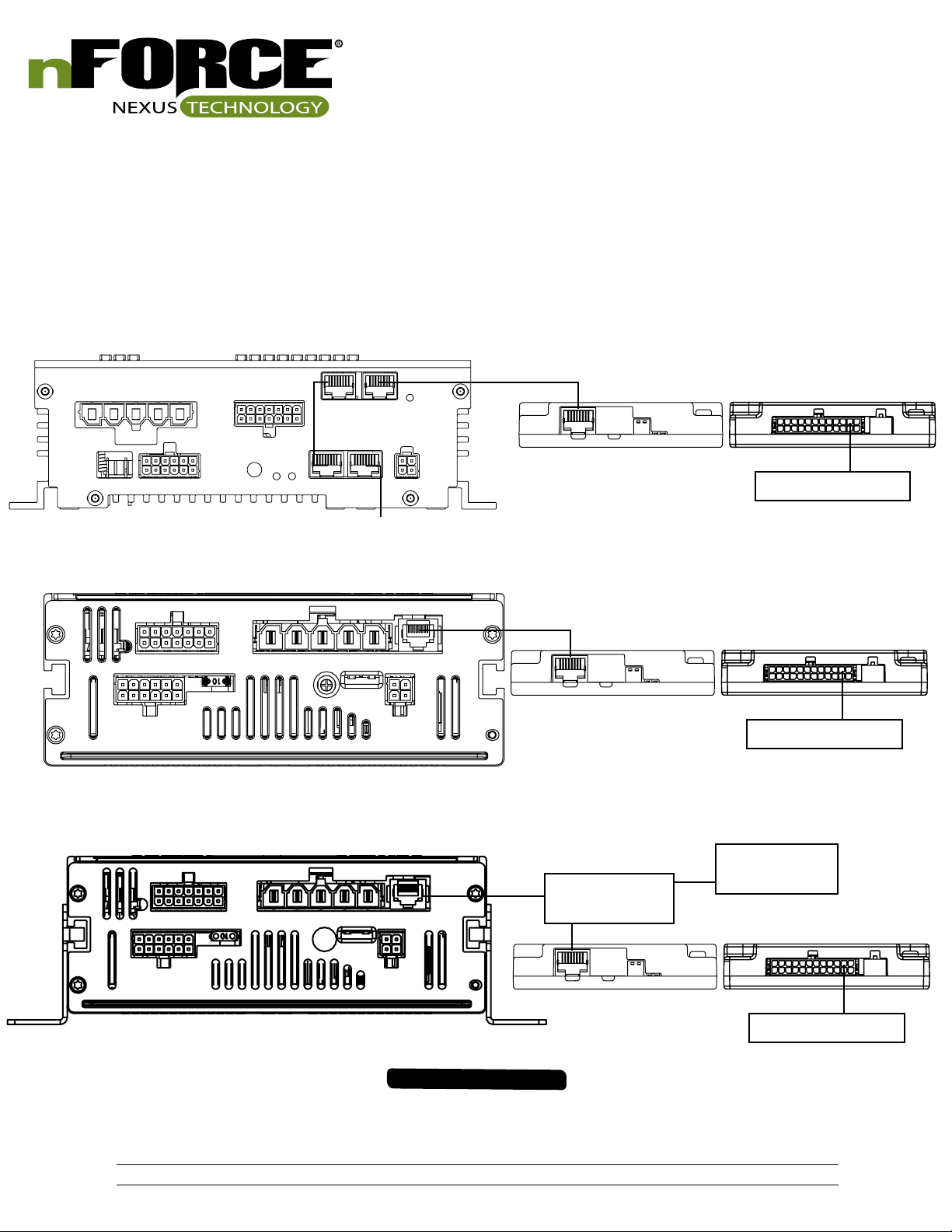
Connection of Lightbar Breakout Box to SoundOff Signal Siren:
Note: Requires PC configuration app to map siren control switches to lightbar functions
Plug 1 end of RJ-45 cable to available jack on siren amplifier
Plug other end of RJ-45 cable to ‘siren’
ETSA380R or ETSA385HR
4" RJ-45 Jumper
Cable
ETSA481CSR or ETSA482CSR
CN6
ETSA481RSP, ETSA482RSP, ETSA461HPP, ETSA462HPP
CN8
CN3
CN2
CN5
Breakout Box - Back
Breakout Box - Back
RJ-45 Splitter
(user supplied)
Breakout Box - Back
Breakout Box - Front
Lightbar
Breakout Box - Front
Lightbar
Siren Controller
Breakout Box - Front
Lightbar
IMPORTANT INFORMATION:
Warning devices are strictly regulated and governed by Federal, State and Municipal ordinances. These devices shall be used ONLY on approved vehicles. It is the sole responsibility of the user of these devices to ensure compliance.
To review our Limited Warranty Statement & Return Policy for this or any SoundOff Signal product, visit our website at www.soundoffsignal.com/sales-support.
If you have questions regarding this product, contact Technical Services, Monday - Friday, 8 a.m. to 5 p.m. at 1.800338.7337 (press #4 to skip the automated message).
Questions or comments that do not require immediate attention may be emailed to techservices@soundoffsigal.com.
SUPERIOR CUSTOMER RELATIONSHIPS. SMARTLY DESIGNED LIGHTING & ELECTRONIC SOLUTIONS.
11.
ENFWBF(xx)0(x) 5.14
Page 12

nFORCE LED Interior Lightbar
REAR INTERIOR LIGHTBAR
3
5
6
2
4
REPLACEMENT PARTS & ACCESSORIES
ITEM
#
1 PNFWBTE003 TRIM EDGE
2 PNFWBDRV01 DRIVER BOARD
3 PNFWBB(xxx)0(x)-(x) SHROUD KITS
4 PEPL8M14
5 PNFWBMRF(x)0(x) REAR MOUNT KITS
6 PNFWBLS106A AMBER 6 LED INBOARD MODULE
6 PNFWBLS106B BLUE 6 LED INBOARD MODULE
6 PNFWBLS106G GREEN 6 LED INBOARD MODULE
6 PNFWBLS106R RED 6 LED INBOARD MODULE
6 PNFWBLS106W WHITE 6 LED INBOARD MODULE
6 PNFWBLS109A AMBER 9 LED INBOARD MODULE
6 PNFWBLS109B BLUE 9 LED INBOARD MODULE
6 PNFWBLS109G GREEN 9 LED INBOARD MODULE
PART# DESCRIPTION
PNFWBJ00 BREAKOUT BOX
PEPL9BBHN(x)
PNFWBHNM0(x) MODULE HARNESS - VARIUS LENGTHS
PNFWBHNP01 POWER HARNESS
PNFWBHNJ01 JUMPER HARNESS
PNFWBMFP(x)0(x) MOUNT KITS
PNFWBMFS(xx)0(x) MOUNT KITS - PASSENGER
BREAKOUT BOX HARNESS - SHORT/
LONG
UNIVERSAL MOUNT KIT - DRIVER/
PASSENGER
1
DATE
FRONT INTERIOR LIGHTBAR
ITEM
#
6 PNFWBLS109R RED 9 LED INBOARD MODULE
6 PNFWBLS109W WHITE 9 LED INBOARD MODULE
6
6
6
6
6
6
6
6
6
6
6 PNFWBLT118GAW GREEN/AMBER/WHITE 18 LED TRI INBOARD MODULE
6 PNFWBLT118RAW RED/AMBER/WHITE 18 LED TRI INBOARD MODULE
6 PNFWBLT118BRA BLUE/RED/AMBER 18 LED TRI INBOARD MODULE
6 PNFWBLT118BRW BLUE/RED/WHITE 18 LED TRI INBOARD MODULE
PART# DESCRIPTION
PNFWBLD112F AMBER/WHITE 12 LED DUAL INBOARD MODULE
PNFWBLD112M BLUE/AMBER 12 LED DUAL INBOARD MODULE
PNFWBLD112E BLUE/WHITE 12 LED DUAL INBOARD MODULE
PNFWBLD112P GREEN/AMBER 12 LED DUAL INBOARD MODULE
PNFWBLD112H GREEN/WHITE 12 LED DUAL INBOARD MODULE
PNFWBLD112K RED/AMBER 12 LED DUAL INBOARD MODULE
PNFWBLD112J RED/BLUE 12 LED DUAL INBOARD MODULE
PNFWBLD112L RED/GREEN 12 LED DUAL INBOARD MODULE
PNFWBLT112D RED/WHITE 12 LED DUAL INBOARD MODULE
PNFWBLT118BAW BLUE/AMBER/WHITE 18 LED TRI INBOARD MODULE
A
IMPORTANT INFORMATION:
Warning devices are strictly regulated and governed by Federal, State and Municipal ordinances. These devices shall be used ONLY on approved vehicles. It is the sole responsibility of the user of these devices to ensure compliance.
To review our Limited Warranty Statement & Return Policy for this or any SoundOff Signal product, visit our website at www.soundoffsignal.com/sales-support.
If you have questions regarding this product, contact Technical Services, Monday - Friday, 8 a.m. to 5 p.m. at 1.800338.7337 (press #4 to skip the automated message).
Questions or comments that do not require immediate attention may be emailed to techservices@soundoffsigal.com.
SUPERIOR CUSTOMER RELATIONSHIPS. SMARTLY DESIGNED LIGHTING & ELECTRONIC SOLUTIONS.
12.
ENFWBF(xx)0(x) 5.14
Page 13

nFORCE LED Interior Lightbar
WARRANTY & RETURN GOODS PROCEDURE
MOUNTING INTEGRITY:
A review of bolt/hardware/mounting bracket integrity should be performed
at the beginning and end of each shift.
WARNING MESSAGES - PLEASE READ:
WARNING - DRILLING ANY HOLES INTO THE LIGHTBAR IS NOT
RECOMMENDED! THE RISK OF DAMAGING INTERNAL COMPONENTS
AND THE RESULTING FAILURE OF THE LIGHTBAR WILL VOID ANY
WARRANTY OF THIS PRODUCT.
WARNING - CARE MUST BE TAKEN WHEN DRILLING THROUGH
THE ROOF OF THE VEHICLE NOT TO DRILL INTO ANY EXISTING
WIRING AND NOT TO DRILL THROUGH THE HEADLINER OR SUPPORT
MEMBERS OF THE VEHICLE. CHECK BOTH SIDES OF THE MOUNTING
SERVICE PRIOR TO DRILLING. DE-BURR ANY HOLES AND REMOVE
ANY METAL SHARDS OR REMNANTS. INSTALL GROMMETS INTO
ALL WIRE PASSAGE HOLES.
WARNING - ROUTE WIRES ONLY IN LOCATIONS THAT ARE NOT
SUBJECTED TO POTENTIAL WEAR. MAKE SURE TO AVOID ROUTING
WIRES IN THE DEPLOYMENT AREA OF YOUR AIR BAG. REFER TO
YOUR VEHICLE OWNER’S MANUAL FOR AIR BAG DEPLOYMENT
ZONES.
WARNING - ALL CUSTOMER SUPPLIED POWER WIRES CONNECTING
TO THE POSITIVE (+) OR NEGATIVE (-) BATTERY TERMINAL OR
LOCAL CHASSIS GROUND (-) MUST BE SIZED TO SUPPLY AT LEAST
125% OF THE MAXIMUM CURRENT AND PROPERLY FUSED AT THE
POWER SOURCE WITH APPROPRIATELY RATED FUSE.
IMPORTANT: When passing cables through fire wall or other sheet
metal, insert grommet to protect the cable!
WARRANTY RETURN PROCESS:
Please contact your SoundOff Signal Sales Representative, Customer Services
staff or our Technical Department (800.338.7337) for a RMA #, Return
Merchandise Authorization Number.
The following information is required for issuance of the RMA #:
• Reason for returning the product*
• Address where replacement product is to be shipped*
• Telephone number where you may be reached*
• SoundOff Signal invoice number on which product was purchased**
• SoundOff Signal part number and serial number**
• E-mail address where RMA # should be e-mailed**
• Fax number where RMA # should be faxed**
* RMA # will not be given without this information.
** If available, please provide this information.
SoundOff Signal will NOT accept returns without an RMA #. Each RMA #
is good for only one (1) return and will expire (10) days after the date it was
issued. Products must be shipped back to SoundOff Signal and the RMA #
clearly marked on the outside of the package near the shipping label. Please
use the following address on your shipping label:
SoundOff Signal
ATTN: RMA # / Technical Services
3900 Central Parkway
Hudsonville, MI 49426
WARRANTY EXCLUSIONS:
Shipping & Handling, labor and service fees are non-refundable. SoundOff
Signal is not liable for any damage due to installation or personal injury as a
result of using SoundOff Signal product.
WARRANTY FORFEITURE:
Warranty will not be granted if the Warranty Return Policy & Procedure rules
are not strictly followed. Physical damage resulting from customer abuse
will void warranty. Warranty will also be voided if any SoundOff Signal and/
or manufacturer serial tags, product stickers, seals, or the like, are removed,
altered or tampered with. Returned product that is damaged by shipping via
the RMA # procedure is not the responsibility of SoundOff Signal.
Document effective date on cover and below supersedes previously dated
policies and statements.
There are no other warranties, expressed or implied, including, but not limited
to, any implied merchantability or fitness for a particular use. SoundOff
Signal reserves the right to modify this warranty statement at any time; or to
discontinue, modify, or upgrade any products of its manufacture with design
improvements without prior notice.
IMPORTANT INFORMATION:
Warning devices are strictly regulated and governed by Federal, State and Municipal ordinances. These devices shall be used ONLY on approved vehicles. It is the sole responsibility of the user of these devices to ensure compliance.
To review our Limited Warranty Statement & Return Policy for this or any SoundOff Signal product, visit our website at www.soundoffsignal.com/sales-support.
If you have questions regarding this product, contact Technical Services, Monday - Friday, 8 a.m. to 5 p.m. at 1.800338.7337 (press #4 to skip the automated message).
Questions or comments that do not require immediate attention may be emailed to techservices@soundoffsigal.com.
SUPERIOR CUSTOMER RELATIONSHIPS. SMARTLY DESIGNED LIGHTING & ELECTRONIC SOLUTIONS.
13.
ENFWBF(xx)0(x) 5.14
 Loading...